A Semi-Autonomous Cost Effective Erection Method for Overhead Line Towers
Authors
B. JACOBS - Doctoral Student, Dept. of Mechanical & Automation Eng, Tshwane University of Technology, South Africa
Dr. D.A. DESAI - Section Head and Senior Lecturer, Dept. of Mechanical & Automation Eng, Tshwane University of Technology, South Africa
Dr. L. J. DU PLESSIS - Senior Lecturer, Dept. of Mechanical & Aeronautical Eng, University of Pretoria, South Africa

Summary
Huge costs are associated with the construction of overhead power lines in the Extra High Voltage category. More economical ways to perform the different aspects of line construction are constantly sought. One area of construction, which is the focus of this study, is alternative erection methods for the towers that support the conductors. Mobile cranes have become the dominant piece of equipment to erect these towers as they occupy a relatively small footprint, and although relatively quick, these cranes do come at a substantial cost. Furthermore, their mobility in terms of terrain is limited. Hence, this paper investigates a promising concept to lift guyed V towers used in overhead power line construction, utilising only winches and a gin pole. Once the tower is correctly assembled and support equipment like gin pole, hinge mechanism and winches are in place, a control system ensures autonomous lift in two stages. This paper further looks at scale model testing that was conducted to prove the concept, the associated electronic control system required and an analytical tool which provide support as well as an air cushion as a future alternative for the gin pole. Comparison of the analytical tool data versus other calculated methods is presented and its importance is explained.
Keywords
Air cushion – analytical tool – gin poles – guyed V-tower – mobile cranes – overhead power lines – winches1. Introduction
Lattice steel towers is predominantly used to support the conductor bundles in South Africa, with its 31 000 km [1] of overhead power lines in the 132 kV up to 765 kV range. Different types of towers are utilised with guyed type towers, for example guyed-V and cross rope type, used on a large scale due to the abundant open and flat terrain.
Mobile cranes are normally used by contractors responsible for constructing overhead lines and erecting the towers in this voltage range. Crane sizes vary from 70 ton capacity up to 250 ton depending on the line voltage and subsequent tower size (mass and height). Often, due to the height of the towers, a bigger capacity crane is required simply to achieve the required reach (height) without using the crane to its limit in terms of lifting capacity.
South Africa is classified as a semi-arid country [2] and often unfavourable terrain conditions (like semi desert and loose sand) are encountered that hinder the mobility and operation of the crane. In these conditions additional equipment and sometimes also alternative construction techniques are required that add to the construction cost.
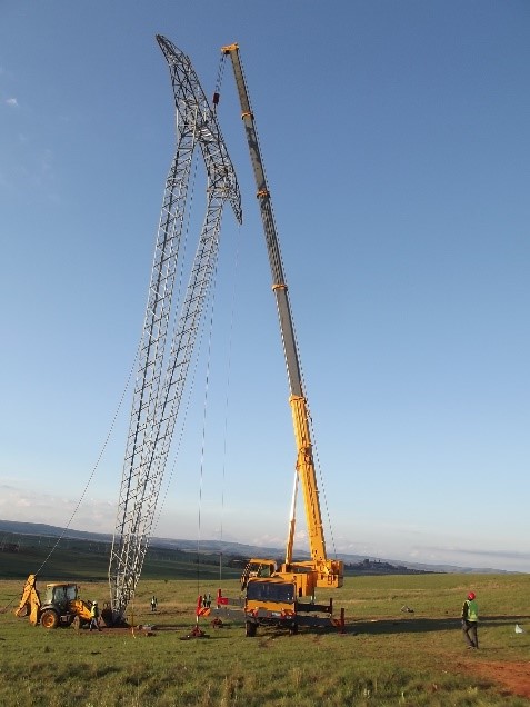
Figure 1 - Erection of a 400 kV type 520B guyed V-tower
Alternative construction techniques include helicopter construction [3] which add a significant cost component, either in terms of money or time to the project. It is therefore justified to develop an alternative lifting method specifically for the guyed V- type towers utilising a gin pole and winches, which is more mobile and cost effective compared to cranes. The proposed gin pole and winch set-up was investigated by Jacobs B, Desai D and du Plessis L [4] and this concept is experimentally tested with a 1:6 scale model and presented here. The tower type investigated is a type 520B guyed V lattice steel construction, designed for 400 kV to carry triple “Dinosaur” conductor in a horizontal phase configuration and with phase spacing of 8.5 m. See figure 1. The tallest type 520B guyed V-suspension tower has an overall tower height of 39.65 m, a conductor attachment height of 33.0 m and with a mass of 7 960 kg.
2. Brief overview of alternative lifting concept
Research conducted by Jacobs B, Desai D and du Plessis L [5] provided key boundary conditions for the alternative lifting concept and concluded that the minimum length of gin pole to lift a full scale type 520B guyed V- tower is 9 m, and for the maximum it was set at 18 m. These gin poles will be modular in design with section lengths of 1.5 m that can be adjusted to suit winch size, rigging setup and terrain conditions. The concept entails complete assembly of the tower on the ground as close as possible to its foundation and in-line with the running direction of the overhead line. A hinge mechanism will be positioned with jacks over the tower foundation and the tower bottom will in turn be attached to the hinge mechanism. The type 520B guyed V-tower was designed for sloping ground of no more than 15°. If sloping ground is encountered the tower will be supported by dunnage to keep it as level as possible. The hinge mechanism will also be levelled. The height and position of gin pole as well as position of winches need to be determined and positioned in accordance with an analytical “safety tool” that will determine the safe positioning and size of equipment required for the operation. Any temporary anchor points are then positioned which will cater for the horizontal forces exerted on the hinge mechanism. The temporary anchor points can be a combination of concrete blocks in steel frames or the existing guy anchor foundations. For safety reasons, the two back guy anchor ropes of the tower, will be connected to its foundations to prevent the tower from over-shooting the 90° vertical position once upright. Next all the lifting ropes are attached and the necessary sensors like load cells, angle inclinometers and accelerometers are connected to a control system.
Lifting can now commence by means of the main winch while secondary winches will ensure stability of the tower during the lifting process under command of the control system. Due to the inherent instability of a guyed V-type tower, a number of lifting and stabilizing ropes will be required, as manual control of such ropes when using winches may be difficult and unsafe for a human operator. Hence, the control system will use input data like tensions in the different ropes, rate of lift and angle of tilt and will control the winches to maintain a stable and safe lift. This part of the lifting process will happen autonomously without any human input except to keep a watchful eye to interrupt or stop the lifting process in case of emergency. Once the tower is upright, workers will use jacks to lower the tower onto its foundation, the permanent guy ropes will then be attached to its anchors and the hinge mechanism removed. Workers can then disconnect all other construction ropes and equipment and move it to the next tower.
3. Scale model testing
A 1:6 scale model made from steel sections was designed and built. This model and gin pole(s) represents the full scale tower in terms of basic geometry, mass and centre of gravity. Using the scale model, testing was conducted at the tower test facility of Eskom in South Africa and the basic test set-up can be seen in figure 2.
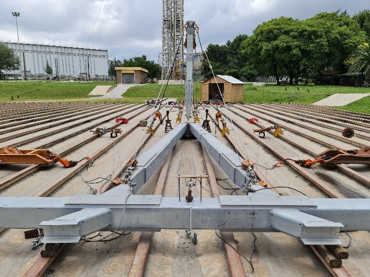
Figure 2 - Test set-up of model tower with gin pole
The key aspects and reason for the tests are to confirm a suitable size of winch that will be required to perform the lifting as well as the number of stabilising winches required to ensure a safe but practical lift. Validation of the calculated loads required by the main lifting winch was also performed during testing. Most importantly, the tests proved that the lifting can be done autonomously in two stages (refer section 4) with the aid of a control system that activate the required winches sequentially as and when required, by using data from sensors.
Three scale gin poles with modular variable dimensions of 1.5, 2.25 and 3.0 m were used for testing. The model tower and gin pole were connected to the test bed with a model hinge mechanism that was securely fastened to the test bed. The model hinge mechanism was designed to handle the required longitudinal and vertical forces during lifting of the scale tower. There are various methods to attach the gin pole to the hinge mechanism and it is envisaged that in practice a mechanical (single) pin and socket type mechanism, that can only handle vertical or compression loads, will be implemented. For example a pin, protruding through the bottom part of the gin pole, will ensure that the gin pole does not slide off its connecting socket that is integrated in the hinge mechanism. This arrangement means that it cannot withstand uplift force. This simple pin type attachment will have the advantage that the erection and positioning of the gin pole can be done quickly, by simply lifting the gin pole off the pin and hinge mechanism, before moving the rig to the next tower to be lifted. For the model testing conducted, the gin pole and bottom tower legs were secured to the hinge mechanism shaft, so that it cannot separate for safety purposes during testing.
4. Rigging set-up
In order to raise a predominantly top heavy structure, initially a total of seven winches were implemented, to cater for all possible imbalance lifting scenarios. This was later reduced to five and can be seen schematically in figure 3. A main winch (W1) is attached to the gin pole which in turn is attached to the tower and is responsible for the main lifting operation. Winches 4 and 5 are responsible for transverse stability to keep the tower upright during lifting. Winches 2 and 3 are used for the second phase of lifting (if required) and will take over from winch 1 which is explained below.
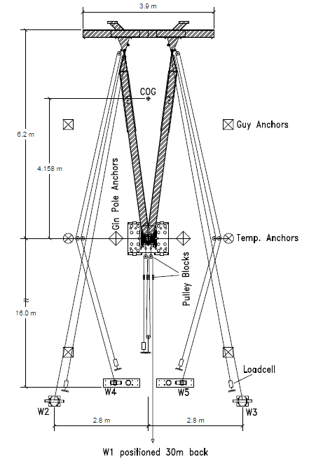
Figure 3 - Plan view of model test set-up showing key dimensions and position of winches
Depending on the distance of main winch 1 from the gin pole and whether directly connected to the winch or via additional pulley blocks, the lifting angle (see figure 4) of the tower is potentially limited. From figure 4 it can be seen that if C = H and with dimension F being very small, the tower can be lifted in one step to a near vertical (final) position. In this case, only the main winch and the two smaller stabilising winches (W4 & W5 in figure 3) will be required. If C > H then uplift of the gin pole can be experienced at some angle
, and as mentioned before, this should be avoided depending on the attachment method of gin pole to hinge mechanism. In such case the lift must be executed in two stages;
- Stage 1: winches 1, 4 and 5 lifting the tower to
= 30° (
- Stage 2: winches 2, 3, 4 and 5 lifting the tower to
In the test set-up used for the model testing the main winch 1 was positioned some distance away from the test bed and pulley blocks were used to “simulate” a direct connection to the winch.
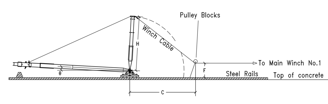
Figure 4 - Side view of model test set-up showing position of main winch1 and its connection to gin pole
The gin pole itself is supported by two ropes in the transverse plane and if positioned on the hinge line, will not require length adjustment during the lifting process. With reference to figure 3 it can be seen that a pulley block is used for each winch rope which enabled a fix point with load cell in close proximity to the control system. This also effectively provided a mechanical advantage of two for the winches, except for the main winch 1 where a mechanical advantage of four was used.
5. Control system
With potentially a two-step process required for lifting, and an inherently top heavy unstable tower, consideration of the number of winches required, is important. The objective is to ensure a stable and safe lift. The more winches required the more complex the lifting operation becomes. Although the lifting process would be possible under manual control, it is the goal of this research to develop a control system that will perform the tower lift process autonomously with minimal human input. This will ensure smoother and quicker operation compared to manual control and potential errors can be eliminated by stopping the system if something becomes unstable or if overloaded. Furthermore, automation in the overhead line industry is limited to inspection [6] of the conductors and then also performing limited maintenance work under live conditions [7], with very little, if any, evidence of automation in the construction field of overhead lines. Hence, the work presented here could be considered as an important contribution to automation in the construction environment for overhead lines.
For any system to work autonomously, it requires amongst others, input data and this is normally supplied by sensors [8],[9]. For the control system used in the scale model testing, the force in the rope of each winch is monitored by load cells. An angle sensor which measures tilt in only one plane is used to measure the overall lift or tilt angle of the tower from an initial horizontal (0°) position to a final upright (90°) position in the longitudinal plane. This longitudinal plane also coincide with the direction of the conductors that the tower is normally supporting. A gyro sensor which measures movement in three planes is used to measure sideways tilt of the tower in the transverse plane. The sensor data is fed into a microprocessor type ATmega2560 with a clock speed of 16 MHz [10]. This microprocessor is conveniently packaged in an Arduino Mega printed circuit board with 54 digital input/output pins and 16 analogue input pins.
Control of the winches is done by relays that power the winches in either the forward or reverse direction. Four of the winches are of the type used in the automotive off-road industry typically used to recover vehicles or launch boats. Two of the four winches used have rated line pull capacities of 15.58 kN (winches 4 and 5) whilst the other two are rated at 35.6 kN (winches 2 and 3) and all driven by 12 V DC motors. The main winch (winch 1) has a rating of 49.05 kN and is powered by a 380V AC three phase induction motor.
Programming of the microprocessor was initially done using the Arduino programming language and the Arduino Software (IDE) which is an open-source platform widely used by a community of students, hobbyists, programmers, professionals etc. Revision 2 of the code has been done in VisualStudio which is a more user friendly environment. The custom developed GUI (Graphical User Interface), which can be seen in figure 5, is used to interface with the microprocessor and to monitor important sensor parameters.
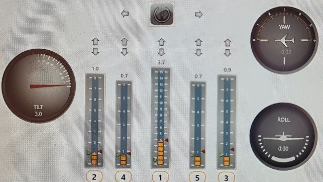
Figure 5 - Graphical User Interface screen of control system indicating sensor data
This GUI shows the tensions in the cables of five winches, the tower tilt angle (around y-axis relative to the horizontal plane), the yaw angle (rotation around the z-axis) and roll (rotation around the x-axis or tilt in the transverse plane) as can be seen in figure 6.
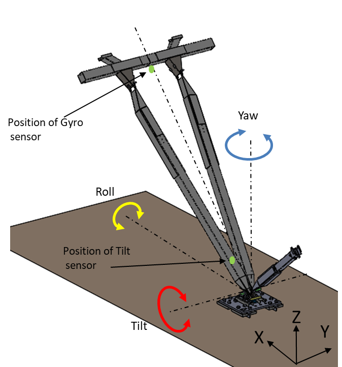
Figure 6 - Control system axis orientation for sensors
The tilt sensor is positioned at the bottom of one of the legs of the tower, whilst the gyro sensor is suspended at the top in the centre of the tower. Trial and error confirmed that the best orientation for the gyro sensor is not to fix it rigidly to the tower top, but to rather suspend it using a gimbal type frame which kept the sensor in a horizontal plane regardless of the tilt angle of the tower. It was further determined that when a tilt angle of about 40° is reached, rotation of the tower around the z-axis (yaw) cannot effectively be measured further with the yaw sensor and the control system then automatically switches over to the roll sensor (rotation around x-axis) to keep the tower upright. Data is stored at a rate of eight readings per second and includes mode of operation, lifting stage, yaw angle, roll angle, tilt angle, W1 to W5 load cell readings as well as whether W1 to W5 is pulling, slacking or off.
Before lifting can commence with the aid of the control system, the following checks need to be confirmed;
- The distance of main winch 1 away from the hinge mechanism to determine whether a single step or two-step lifting process will be required.
- In case a two-step lift will be required, the tilt angle where step one will stop and step two will commence, needs to be determined.
- Connection of the back guy ropes of the tower is in place to prevent over-shoot of the tower, pulling it accidently more than the required 90° upright.
- Confirm all sensors are calibrated.
- Manual tensioning of the winches to take up slack and verifying that all sensors provide correct data readings.
- Visual safety check to confirm all rigging is sound and safe, no cables are twisted or kinked, all pulley blocks are free to rotate and all workers is maintaining a safe distance.
Steps a) and b) of the above procedure, together with other key parameters, are available from an analytical tool that has been developed to perform these calculations (See section 7).
The following steps are performed continuously by the microprocessor for a two-step lifting process:
- Program starts once the reset button on the control panel is pressed to set the tilt and gyro sensors readings to zero, then switches on main winch 1 to commence lift.
- Read tilt angle sensor, read yaw sensor, read load cell values from all load cells.
- Compare tilt angle sensor value to end-of-step one pre-determined value, compare yaw sensor value to be within allowable tolerance and compare load cell values of winches 4 and 5 to be within allowable tolerance.
- Switch winches 2, 3, 4 and 5 on or off depending on sensor values and limits as required to maintain stable and level lift. If for example the yaw sensor detects movement of tower outside pre-determined tolerance values, the corresponding stabilising winch (4 or 5) will increase or slack tension to correct yaw movement detected. Similarly tensions in winches 2 and 3 are maintained and controlled not to exceed the tension in main winch 1 which is continuously running.
- Once a tilt angle of 40° is reached, stop readings from yaw sensor and use readings from roll sensor, whilst the lift is in progress.
- Once the pre-determined tilt angle for the commencement of phase 2 lift is reached, stop all winches. This gives the opportunity to do a visual safety check and to verify rigging and whether the tower is still stable and ready to be lifted further. At this point minor adjustments can be made manually with the applicable winches to correct the tower alignment if necessary.
- Press button on control panel to commence phase 2 of the lift, where winches 2 and 3 continue with the lift (winch 1 is not further used from this point) while winches 4 and 5 maintain the tower in upright position using data from the roll sensor.
- Once tilt angle reaches 80° all winches will stop and the lift will be complete.
The autonomous lift will be completed at 80° since the last 10° will be done manually with the front guy ropes and to plum the tower in the longitudinal and transverse planes using survey equipment as per normal practice.
6. Test program
For safety reasons a number of trial runs have been done with the control system to verify the correct working of all components and elements prior to starting the test program. One of the goals of this research is to have the option and ability to lift the tower completely assembled including insulators, line hardware and running blocks connected. This will increase the total mass to be lifted.
The final test program comprised lifting the tallest scale model type 520 guyed V-tower (1 300 kg) using the three different lengths of gin poles, as mentioned earlier, with and without the simulated insulators and hardware. The additional scaled load that simulated the insulators, line hardware and running blocks was calculated at 0.981 kN extra per phase yielding a total additional load of 2.943 kN. Table 1 provides the test programme in more detail.
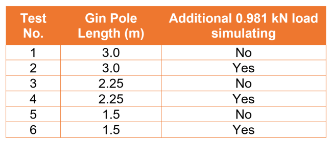
Table 1 - Test programme
7. Analytical tool
There are many different options and combinations in which the gin pole and winches can be used to lift the 520B guyed V-tower. These options may be limited by terrain conditions on site and the equipment the contractor may have, specifically in terms of winch capacities. Furthermore, conditions on site are not always favourable to perform calculations and therefore up-front planning to use this alternative lifting methodology is important. Software tools available to the contractor in the line construction industry for specific applications like this, are also limited which is evident from the TrustRadius website [11] where the bulk of the software evaluated focusses more on construction and project management aspects. The most relevant software that could be sourced is from suppliers of ERS (Emergency Restoration Systems) where the software assists with the design of temporary by-bass construction for where overhead lines have been damaged [12].
As a result an analytical software tool has been developed to assist contractors in determining the ideal winch position for a specific winch capacity or alternatively the winch capacity required for a pre-defined winch position. Other input parameters like gin pole height to be used, tower height and mass as well as whether insulators with hardware will be lifted together, are also entered. The different tower heights to be lifted together with all its corresponding data are stored in a data sheet where a drop down box type selection is simply made to select the correct tower height. Similarly the gin pole height to be used for the lifting process together with its relevant data is also accessible via a drop down box type selection. Other relevant inputs like winch position, winch offset angle, winch and hinge mechanism height etc. are entered manually. Different coloured cells are used to distinguish easily between where data needs to be entered and where results are calculated. A graphical representation of the lifting set-up is also provided and if certain parameters are exceeded an indication in red will flag the corresponding value in order to rectify or alter it. An example of one of the spread sheet pages can be seen in figure 7.
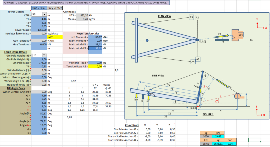
Figure 7 - Example of one page from the analytical tool software calculator
Fundamentally, the calculation principle of the analytical tool is using the sum of the moments around the hinge mechanism shaft. Factors taken into account are the mass of the tower, mass of gin pole, mass of line hardware and running blocks, the mass or tension that may be applied to the back guy ropes as well as the tension force in the main winch rope. Figure 8 indicates the location and direction of these components. The following equation is used in the analytical tool;
Moments cw =
Moments ccw
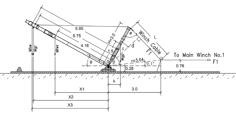
Figure 8 - Position and direction of forces used for analytical tool calculations
The main purpose of the analytical tool is to provide the contractors, responsible for constructing the overhead lines and utilising this gin pole and winch concept, with a safe tool to select the correct capacity winches, together with rigging ropes and equipment needed to safely execute the lift. Furthermore, it will assist to ensure the most economical winch size (capacity) is selected as the main winch will be the most costly item when using this lifting concept.
8. Measurements, calculations and results
Prior to conducting the scale model tests, analytical tool calculations were made to calculate the forces in the main winch no. 1 cable, as it by far accounts for the maximum load in the system. Verification of the analytical tool results were obtained by structure analysis software (PLSTower), where the lifting process was statically simulated in lifting intervals of 5° starting at 0° (horizontally) up to 90° vertical. PLSTower is a well-known finite element analysis software that can model trusses, beams and cable elements quickly and accurately and when using the non-linear solving option, all forces and moments are in equilibrium in the structure deformed state, i.e. P-Delta effects are accounted for. An example of the full scale type 520B guyed V-tower and gin pole, together with the equivalent scale model representation using PLSTower can be seen in figure 9. The model in (a) was used to determine, for the full scale tower, the maximum tension in the winch rope and same for the 1:6 scale model in (b).
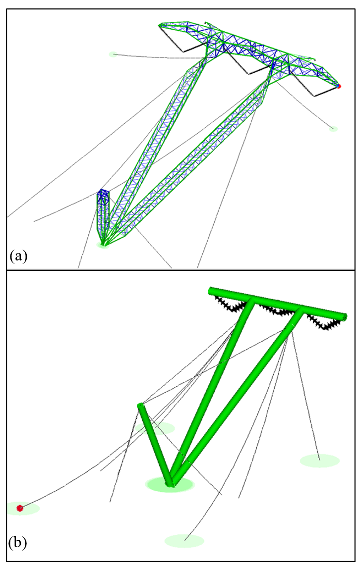
Figure 9 - Example of full scale tower modelled in (a) and 1:6 scale version in (b) using PLSTower
Data obtained from test No.1 where the 3 m gin pole and without 0.981 kN point loads, that simulate insulators and hardware, is further evaluated in more detail. The main winch was positioned 3 m away from the gin pole and results were evaluated in tilt angles of 5°. When the analytical tool and PLSTower results is superimposed over the scale model testing results, the following graph is obtained;
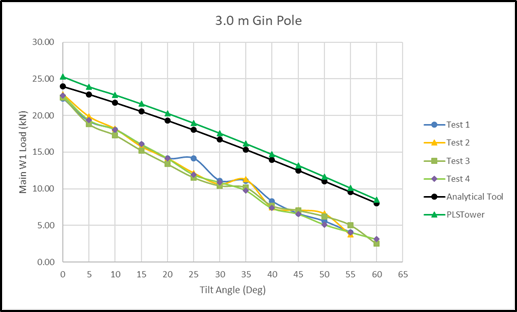
Figure 10 - Graph showing four scale tests, analytical tool and PLSTower results
The four sets of scale model tests that are plotted show good correlation with one another. Furthermore, the analytical tool and PLSTower results equally shows good correlation although the results are higher compared to the measured results. All the results follow the same trend starting at a high value and getting lower as the tilt angle increases which is to be expected. It must be noted that the analytical tool and PLSTower results are static results obtained in tilt angle intervals of 5° whilst the scale test results are dynamic since the tower was lifted continuously from 0° to 60° in a single run. PLSTower does not have the capability of modelling continuous motion and hence the 5° interval approach was used. Since the lifting process is slow due to the general low speed of the winches together with the pulley blocks, which provides a mechanical advantage of 1:4, the static incremented simulation is relevant and acceptable. A similar approach was followed by (Van Zyl et al., 2006)[13] where the analysis of a rotating tippler structure was evaluated in intervals of 10°.
From the measured dynamic data, (as explained in Section 5) “snapshot” data points are plotted when the tower reached the relevant intervals of 5°. Possible reasons for the difference in static versus dynamic results can be inertia effects during the dynamic test, where the body momentum, results in slightly lower tension in the main winch cable. Another aspect that has an influence is the placement of load cell W1 shown in figure 11(a). This placement made it viable to use a wired load cell and to route the wire to the control system processor. However the placement of the load cell and subsequent use of pulleys (P1, P2 and P3 in figure 11(a)) and pulley blocks introduce additional forces in the W1 winch rope needed to overcome the friction in the pulleys and pulley blocks. Load cell W1 in figure 11(a) does not measure these additional forces.
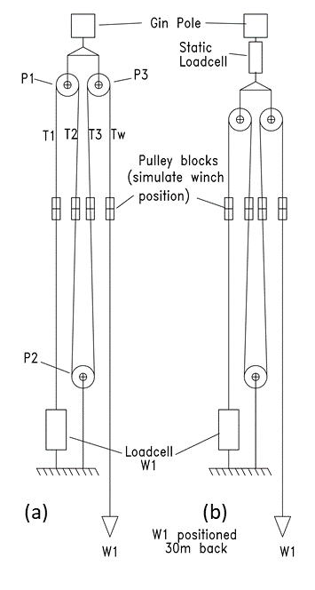
Figure 11 - Position of load cells in rigging set-up
Static tests were therefore conducted using a slightly revised rigging set-up (refer to figure 11(b)). In this set-up an additional load cell was used to measure static results of the total load required to lift the model tower. A comparison of results to the analytical tool once again yielded lower values.
The dynamic inertia moment effect was also studied in more detail and using the equations of motions for rotation about a fixed axis [14] and with reference to figure 12 note the following:
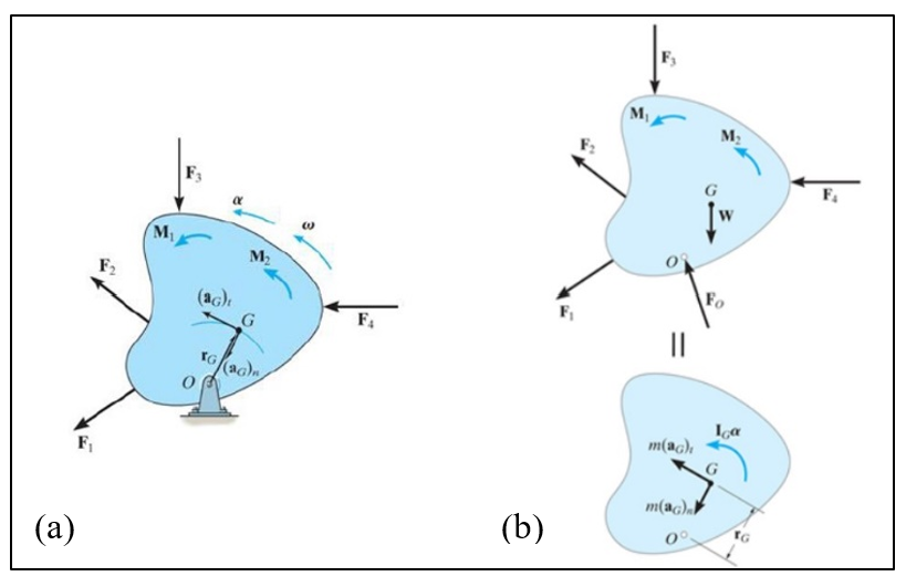
Figure 12 - Diagrams of angular momentum (a) summing moment around point G and (b) summing moment about point O [14]
From figure 12(a) when a body experiences an angular acceleration, its inertia creates a moment of magnitude equal to the moment of the external forces about point G. Therefore,
Then, from figure 12(b) summing the moment about the centre of rotation O yields
From the parallel axis theorem thus the final moment equation of motion is written as;
.
Applying this to the model tower and gin pole combined body, the mass moment of inertia of the total system is obtained from SolidWorks 3D CAD software which was used to design all the components (see figure 13).
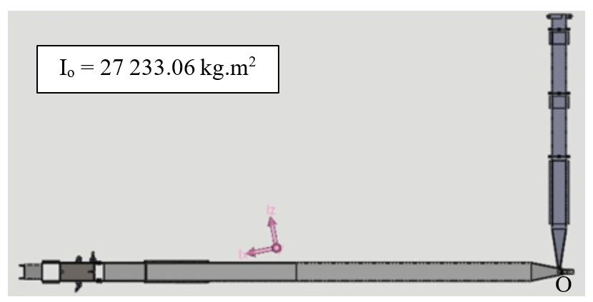
Figure 13 - Position of mass moment of inertia of combined model tower and gin pole system
In order to determine the angular acceleration α of the system the following equations are deduced with reference to Fig. 8.
Calculate L in terms of .
Using Cosine rule;
(1)
Winch speed Vw = 0.0441 m.s-1
At starting position; = 0° and β = 80.9°, d=2.3 m, L=3.92 m.
Taking time derivative of (1)
(2)
Taking time derivative of (2)
Although the winch initially starts at 0 m.s-1 it reaches a constant velocity of 0.0441 m.s-1 in a short time resulting in an initial linear acceleration. However, this will mostly be used to take slack out of the rigging cables before lifting commences. Hence, linear acceleration .
or
A free body diagram of all the forces and moments can be seen in figure 14. Note that the forces due to hardware and insulators as well as bottom guy ropes are not included, since these were not considered for test No. 1.
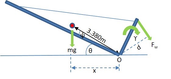
Figure 14 - Free body diagram of forces and moments acting on system
Where;
Using the same moment calculation approach as above for all tilt angle intervals of 5°, the graph in figure 15 is obtained. Note that the results from the graph in figure 10 is still displayed as part of figure 15.
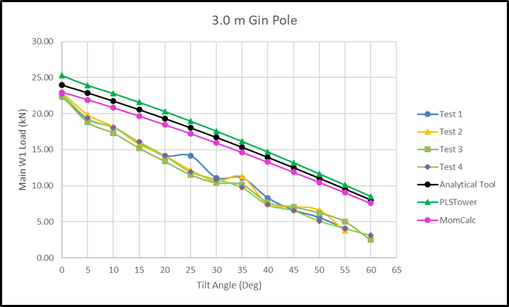
Figure 15 - Graph showing mass moment of inertia calculations results superimposed on previous results
The moment calculations show good correlation with the static calculations (PLSTower and analytical tool). This gives further evidence that the analytical tool is accurate and can safely be utilised in the up-front planning that is needed for every single tower that will be lifted with the alternative lifting technique presented here.
9. Lifting of model tower using an air cushion
A novel concept of lifting the type 520B guyed V tower, and possibly other similar guyed type towers, is to use an air cushion which could potentially eliminate the gin pole and reduce the size of main winch required. Air cushions are regularly used to lift and move heavy machinery and equipment by utilizing the efficiency of the air bearings to move a load on a frictionless film of air. One of the best examples of this concept is the well-known hovercraft. Other applications of air cushions is known as lifting bags or lifting cushions, where the air is pumped into a flexible type rubber bag. Two variants exist where air is either pumped in under high pressure, by means of a compressor and where the bag needs to be capable of handling high pressure or alternatively the air is pumped in under low pressure by means of a blower. Variations of the last mentioned systems can be found in the entertainment industry as jumping castles, water slides, space rockets etc. The concept is to obtain lift by applying a low pressure over a big area.
Very little evidence could be sourced of using air cushions in the line construction industry and the proposal is to use a triangular shaped air cushion of sufficient width that will support the bulk of the tower cross-arms and body. Normally during tower assembly, towers are supported on dunnage to keep them level which in turn provides a gap where the air cushion can be positioned prior to inflating. The required lift height will depend on the type of tower, size of winch and practical limitations in constructing a large enough air cushion.
A scale version of an air cushion was constructed and used to lift the model tower used in this research. After correct positioning of the air cushion under the tower, the blowers were connected and switched on. While the tower raised, two small winches (W4 & W5 figure 3) was used for transverse stability, until a tilt angle of about 30° was reached. During this phase of the lift no gin pole was used. Figure 16 shows details of this test.
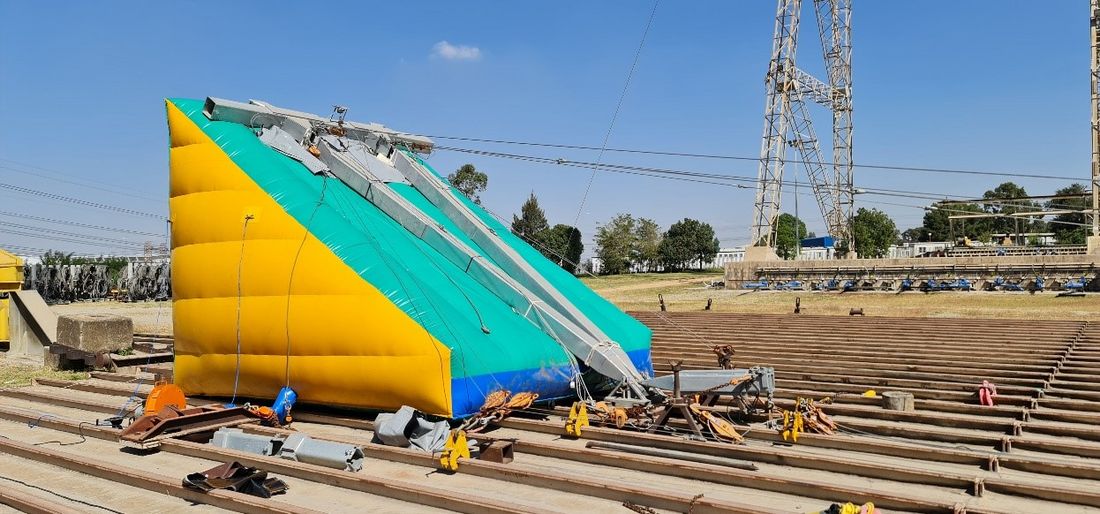
Figure 16 - Use of air cushion to lift model tower – eliminating the gin pole
Once the tower reached the 30° position, two secondary winches completed the lift process to the final 80° position without the aid of a gin pole. Various designs for the air cushion is considered ranging from curved extensions, vertical tubes and square cushions. Experience shows that the best design has a large base which can support the body and cross arms of the tower and with a triangular shape a natural stable lift of 30° is achieved. Long slender designs should be avoided. In practice it is envisaged that the air cushion will be constructed in several segments or cells that are inter-connected so that in case one get damaged or ruptured, no catastrophic collapse will be possible. Furthermore, the compactness of the air cushion when not in use, together with the relative small blowers required, make this a very mobile system ideally suited for use in difficult accessible terrain like semi-deserts.
10. The potential economic viability of the alternative lifting method
The alternative lifting system described here, also known as the “tilt-up” method [15], has been the focus for wind generator erection as well. Ganser et al. [16] concluded in his study of construction for smaller residential wind turbines, that the tilt-up method could present lower costs compared to traditional erection methods which utilise mobile cranes. Another study conducted by Orrell [17] into the installation costs of wind turbines, concluded that a number of projects had minimal installation costs due to the tilt-up method which required very little labour and few tools.
The costing structure for contractors building overhead lines is difficult to obtain, partly due to the open and competitive market they operate in. When high level capital outlay cost comparisons for equipment are made, some indication of the economic viability of the gin pole and winches system can be made. Using a 90 ton mobile crane, which is deemed the smallest size, and normally used by contractors in South Africa, to lift the type 520B guyed V tower, in comparison to a winch with gin pole system, the cost ratio would be 4:1. Thus a 19 ton winch with gin pole system would cost about 25% of a 90 ton mobile crane. Note that the size of winch can be smaller if pulley blocks are used to obtain some mechanical advantage. Obviously, this will result in lower lifting speeds which in turn will increase the time taken to lift the tower. Apart from capital cost, it is envisaged that the time taken to set up both the mobile crane and gin pole system will be the same once arrived on site. However, the relative ease with which the gin pole and winches can be transported between tower positions will give it an advantage. Very often terrain conditions necessitates that the counter weights of the mobile crane be detached and transported separately in order to allow the crane to move more easily.
A more detailed cost comparison was done using a scenario of six working days to erect only type 520B Guyed V-towers. Consideration was given to set-up time of both crane and gin pole system, the back-stay anchors required for the gin pole and winches, running cost of the crane versus gin pole and estimated labour requirements for both systems. It was further assumed that the same number of towers can be erected with both crane and gin pole system due to the set-up requirements for both. One potential draw back of the gin pole system is the anchor system requirements for both the hinge mechanism and winches. Occasionally concrete blocks with steel sledges are used as temporary anchor systems which are labour and time intensive. A better option would be to make use of the existing guy anchor foundations and although their design is mainly to cater for force application in-line with the guy rope, temporary short props can prevent “bending” of the anchors, yielding them as very cost effective anchoring points. The cost comparison revealed that the gin pole system will cost 63 % of the 100 % benchmark crane system considering total cost incurred over the simulated six day construction period.
An additional important factor to consider is the standing time cost due to equipment break downs. This is a risk contractors take into account and cost accordingly in their price schedule. For mobile cranes this cost is considerably higher when compared to the gin pole and winches or air cushion method.
The gin pole and winches system will also make provision to erect the tower completely “dressed” [18] which is a term used for attaching the insulators, line hardware and running blocks. Normally dressing of a tower is done after the tower is erected and tests conducted with the model tower confirmed that the extra mass of the insulators and hardware can easily be catered for with the proposed lifting system. If erected in one step, this will then be another time saving component.
Due to the better mobility of this alternative lifting system compared to mobile cranes, as well as the significant savings, the system could more easily be duplicated on site with similar systems performing multiple lifts in parallel in different areas of the transmission line.
In comparison to the gin pole and winches system, the air cushion concept will yield potentially even bigger cost savings, since the gin pole with main winch can be eliminated. All that will be required is a set of smaller winches to do the lift and ensure stability. The compactness of the air cushion (when deflated) and blowers will mean smaller transport vehicles that are more mobile and this system too could be duplicated to erect a number of towers simultaneously along the line.
11. Conclusions
This study focused on a gin pole and winches system for lifting the type 520B guyed V-tower, following a previous study by the same authors confirming the most suitable configuration for the gin pole system. To ensure a safe and stable lift and by introducing a degree of autonomous lifting, a control system is used with the support of an analytical tool.
Scale model test results correlate well with the calculations and simulations performed having the same trend and repeatability. The developed analytical tool is critically important for full scale operation of the proposed solution and was verified against PLSTower, moment calculations and static tests on the model. The analytical tool gave more conservative values to the scale test results and thus will provide an additional margin of safety.
The alternative lifting concept presented can be scaled up or down to for example lift taller and heavier guyed V-towers for example used on 765 kV. Similarly, on smaller voltage lines where the availability of mobile cranes may be difficult (as in many African countries) and where access to tower positions is challenging, this concept can offer a viable solution.
Tests with the air cushion and scale model indicate that this is a very stable lifting method requiring only two winches during its lift to ensure the tower remain on the air cushion. It can eliminate the gin pole but due to possible restrictions in achieving a large tower tilt angle, will probably be bound to a two-step lifting process. Once the tower is lifted by means of the air cushion during the first stage, two smaller winches can continue the lift without the need for a gin pole. This will also require less longitudinal back staying for the hinge mechanism as most of the force from the air cushion will be directed vertically up on to the tower during the first stage of lifting. Practical limits as to the physical size of air cushion that can be manufactured for full-scale application need to be determined, but judging from the size of slides available in the entertainment industry this may not pose a problem.
Economic pressures force utilities and contractors, building overhead power lines, to constantly seek alternative and more cost effective ways to erect the towers that are supporting the conductors. Considering the cost for lifting one type 520B guyed V-tower as a benchmark, preliminary cost estimates indicate that the gin pole and winch will cost about 63 % of the 100 % cost basis of the mobile crane and the air cushion in the order of 61 %. Furthermore, it is envisaged that more towers can be lifted with the alternative lifting method due to the relative ease of set-up and mobility of the system.
References
- Eskom, “Eskom Holdings Corporate Plan – Financial years 2016/17 – 2020/2021”, Rep. 240-56927206, pp 179, 2016.
- J.A du Plessis, B. Schloms, “An investigation into the evidence of seasonal rainfall pattern shifts in the Western Cape, South Africa”. Journal of the South African Institution of Civil Engineering, Vol 59, n.4, pp.47-55, Dec 2017.
- Stevens D, “Review of Alternative Construction Methods for Transmission Towers”, Report, University of Cantebury, Feb.2014.
- B.Jacobs, D. Desai, L du Plessis, “An Objective Review of Erection Methods for Overhead Line Towers Devoid of Cranes”, in 2020 IEEE PES/IAS Power Africa, Nairobi, Kenya, 2020 pp.432-437.
- B.Jacobs, D. Desai, L du Plessis, “Novel autonomous lifting of a guyed V-tower: A case study”, South African Journal for Science and Technology, Vol 39, No. 1, pp. 108-115 2020,
- R.S. Gonçalves, J.C.M Carvalho, “Review and Latest Trends in Mobile Robots Used on Power Transmission Lines”, Vol.10 pp. 1-14, 2013.
- CIGRE Technical Brochure 731, “The use of robotics in assessment and maintenance of overhead lines”, WG.B2.52, June 2018.
- P.Debenest, M Guarnieri, K. Takita, E.F. Fukushima, S. Hirose, K. Tamura, A. Kimura, H. Kubokawa, N. Iwama, F. Shiga, Y. Morimura, Y. Ichioka, “Expliner – Toward a Practical Robot for Inspection of High-Voltage Lines”, in Field and Service Robotics, vol.62, A. Howard, K. Iagnemma, A. Kelly Ed, Berlin, Heidelberg: Springer 2010, pp. 45-55.
- R.C. Dorf, R.H.Bishop, Modern Control Systems, 10th ed. New Jersey: Pearson Prentice Hall, 2005, p. 9-10.
- Arduino Mega 2560 Tech Specs, [Online]. Available: https://store.arduino.cc/arduino-mega-2560-rev3.
- Trust Radius – Construction Software, [Online]. Available: https://www.trustradius.com/construction-software.
- Lindsey Systems – Training & Software, [Online]. Available: https://lindsey-usa.com/ers/training-and-software/.
- P.J.A. van Zyl, N.D.L Burger, P.R. de Wet, “Verification of a Finite Element Model of a Rotating Tippler Structure by Means of Strain Gauge Measurements”, R & D Journal of the South African Instituition of Mechanical Engineering, vol. 22, pp.1-15.
- R.C. Hibbeler, Engineering Mechanics – Dynamics, 3rd ed. Singapore: Pearson Prentice Hall, 2004, p. 406-407.
- IEEE Guide to the Assembly and Erection of Metal Transmission Structures, IEEE Std. 951-1996(R2009), Sep.2009.
- Wolkiewicz D, Ganser H, Samaroo MA, Mamayek SB, “Design Framework for Comparing Wind Turbine Tower Erection Methods”, Major Qualifying Projects, Worcester Polytechnic Institute, 2014.
- Orrell AC, Poehlman EA, “Benchmarking U.S. Small Wind Costs - With the Distributed Wind Taxonomy”. United States of America: United States Department of Energy. https://doi.org/10.2172/1400355.
- B. Badenhortst, P. Marais, “The Planning, Design and Construction of Overhead Power Lines”, Johannesburg: Crown Publications cc, 2005, pp 677-722.