A Method for Managing Setting Values of Voltage Control in IEC 61850-based Distribution Automation Systems
Authors
T. OTANI - Central Research Institute of Electric Power Industry, Japan
S. KOBORI - Chubu Electric Power Grid Co. Inc., Japan
Y. MASUDA - Aichi Electric Co. Inc., Japan

Summary
The control functions provided by existing distribution automation systems shall also be implemented in those based on IEC 61850. A sophisticated design is needed, in which several logical nodes incorporate to manage the process of setting values of voltage control. This paper proposes one method of combining logical nodes to achieve this aim, in which all instances of schedule logical node have the same duration and unit intervals for schedule to simplify the maintenance of logical nodes. The method also instantiates the schedule logical node for on-demand setting values as well as one for default values to provide flexibility. It has been implemented and evaluated in a field control unit of a distribution automation system. The results show the tap change control and transition of intervals work well, with only around two seconds required to update setting values. Accordingly, this indicates the viability of the proposed method as a practical, simple and flexible solution.
Keywords
IEC 61850 - Logical node - scheduling - step voltage regulator - feeder - telecommunication - DERNomenclature
CT Current Transformer
DAS Distribution Automation System
DER Distributed Energy Resource
DO Data Object
IEC International Electrotechnical Commission
LN Logical Node
LTC On Load Tap Changer
LV Low Voltage
MV Medium Voltage
SVR Step Voltage Regulator
VT Voltage Transformer
1. Introduction
DASs are installed and operated by grid operators in Japan to secure the power supply and help streamline how distribution grids are operated and maintained. The control functions provided by existing distribution automation systems shall also be implemented in those based on IEC 61850. This includes the management process of setting of voltage control values on feeders using SVR. Where IEC 61850 is applied to distribution automation systems, the management needs a sophisticated design in which several logical nodes incorporate. This is because such designs for logical node combinations are outside the scope of IEC 61850 and thus constitute design issues for individual projects.
This paper proposes a method of combining logical nodes to manage the setting values. Here, all logical node instances for holding setting values would have the same duration and unit intervals for schedule to simplify maintenance of logical nodes. The method also instantiates the logical node for both on-demand setting values and default values for added flexibility. It was implemented and evaluated in a field control unit of a distribution automation system.
This paper is structured as follows. Section 2 outlines distribution automation systems and the application of IEC 61850. Section 3 puts forward a proposal for setting value management using logical node combinations, while Section 4 evaluates the proposed method using implementations in devices that have been practically operated. It also considers feasibility and usability based on evaluation results.
2. Distribution automation systems and the application of IEC 61850
2.1. Distribution automation systems in Japan
Distribution grids in Japan typically comprise MV (6.6 kV) feeders, LV (100 V / 200 V) service lines, MV/LV power transformers, sectionalizers on MV feeders and several other types of equipment, including SVRs. A sectionalizer is a type of switchgear used to change the network topology of distribution grids and isolate faulty sections from the system. Some sectionalizers contain CTs and VTs allowing the current and voltage of the MV feeders to be measured. An SVR usually comprises an autotransformer with adjustable taps (or steps) in the series windings to boost or buck the voltage and the voltage change in the SVR output is obtained by changing the taps of the series winding under load [3]. The rated voltage of most MV feeders is 6.6 kV in Japan, so voltage on feeders shall be controlled using some electrical devices like SVRs in the case of long feeders [4][5].Popular control procedure of the voltage control by SVR is executed according to the scheduled setting values for target voltage, dead bandwidth and/or line drop voltage due to resistance and reactance. Direct control and setting may also be employed for voltage regulation using SVR.
A DAS monitors equipment status such as the sectionalizer position (open/closed), measures the current and voltage of MV feeders and controls equipment including sectionalizers and SVRs. To achieve these functionalities, a DAS comprises a master unit, field controllers and the communication networks connecting them. Master units are usually installed in control centers to gather data from and dispatch commands to field controllers. Field controllers, meanwhile, are usually mounted on a pole with a sectionalizer to send measured values of the current and voltage of an MV feeder and receive commands from a master unit. They also include some autonomous functions including reclosing of sectionalizers based on timer and detection of earth fault directions. Another type of field controller is mounted on a pole with an SVR to send the tap changer position and voltage and receive commands and/or setting values for SVR control. It also autonomously controls the SVR according to the schedule set by the master unit in advance.
DASs are installed on almost all MV feeders in Japan and help ensure highly reliable power supply for customers [1][2]. However, most existing DASs are implemented with proprietary communication technology such as cyclic digital transfer (CDT) and information technology without information models. If communication technology and information models based on international standards, it would be expected to facilitate implementation using off-the-shelf software component, secure interoperability and be used in other countries.
2.2. Voltage control of feeder
For voltage control via SVR, the specific SVR terminal on the side connected to a substation must be identified. This is because the network topology of distribution grids is often changed to facilitate grid operations and/or facility maintenance. Changes like this may switch the SVR terminal that is connected to a substation because normal operations involve network topologies that are radial and start from a substation. Figure 1 depicts an example of terminal switching resulting from a change in network topology within the distribution grid. Terminal A of SVR is connected to the substation on the left-hand side via the closed sectionalizer and Terminal B is disconnected from the substation on the right-hand side in the case of network topology 1. When an operator controls the sectionalizers, the network topology changes from #1 to #2. After the operator’s intervention, Terminal B of SVR is connected to the substation on the right-hand side. The mode of the voltage control function changes based on the SVR connection with the substation.
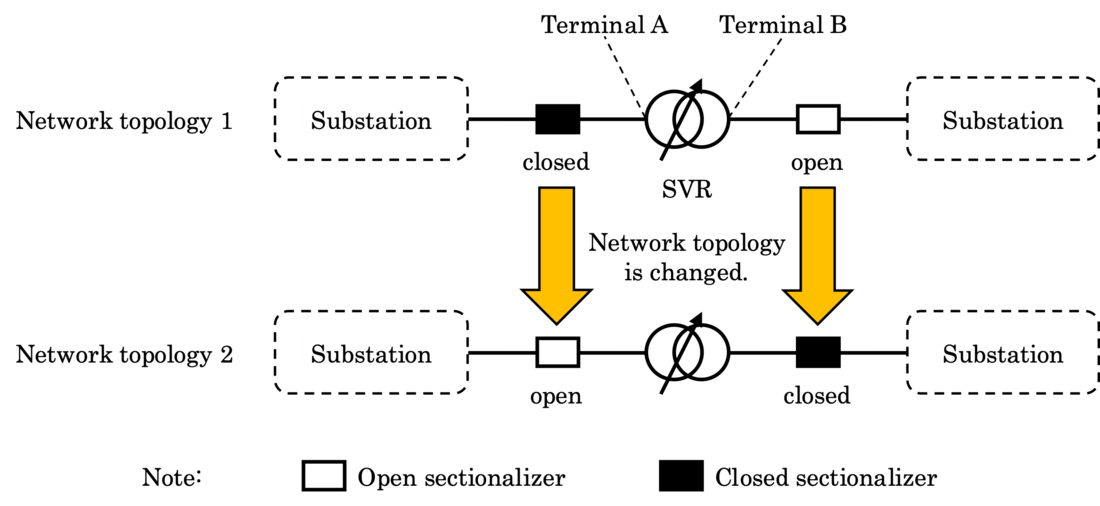
Figure 1 – An example of terminal switching caused by network topology change of distribution grid
IEC 61850 has not been applied to voltage control using SVR to date, for the following reasons. First and foremost, prior to our proposal, DASs in Japan employed proprietary communication technologies [6]. Secondly, the structure of distribution grids in Europe, where many IEC 61850-based systems have already been deployed, differs from that in Japan [7], hence the voltage control is also different. Finally, the market for DASs is still growing, so the functionality of feeder automation has yet to be deployed in much of the world [8].
2.3. Application of IEC 61850 to distribution automation systems
Figure 2 outlines DAS with IEC 61850 applied, whereby LN instances are installed into field controllers to execute autonomous functions and communicate with the master unit. For example, a field controller for a sectionalizer uses an MMXU instance to digitalize current and voltage signals from the CTs and VTs installed in a sectionalizer and calculate their RMS values. The RMS values are then provided to the master unit via the communications defined in IEC 61850. The field controller also uses an instance of CSWI to open or close the sectionalizer according to a command sent from the master unit. An instance of PSDE in the field controller provides information about the earth fault direction to identify the fault section. For SVR field controllers, meanwhile, an ATCC instance raises or lowers the SVR tap position according to a command from the master unit or setting values notified by the master unit in advance. To control the SVR based on schedule, an instance of FSCC and those of FSCH provide functionality for scheduling the values to be set to the ATCC instance.
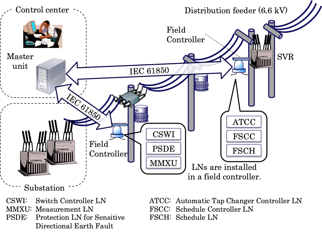
Figure 2 – An Overview of a Distribution Automation System with IEC 61850 applied
2.4. Logical nodes for SVR control
As mentioned in Section 2.3, the schedule-based control of SVR utilizes ATCC, FSCC and FSCH as defined in IEC 61850-7-4 [9].
ATCC includes the DOs listed in Table I for voltage control via tap changer. It raises or lowers the tap position according to an operate request for TapChg via communication networks or setting values configured in the DO settings, such as BndCtr and BndWid. These values can be updated via communications or a scheduling mechanism as provided by a combination of FSCC and FSCH.
| Group | DO name | Explanation |
|---|---|---|
| Status information | EndPosR | If true, end position raises or highest allowed tap position has been reached. |
| EndPosL | If true, the end position lowers or lowest allowed tap position has been reached. | |
| ErrPar | If true, parallel operation error is present. | |
| Measurement values | CtlV | Voltage on secondary of the transformer as used for voltage control. |
| Controls | Auto | (controllable) If true, output circuit of the automatic controller has been enabled (control is automatic), otherwise control is manual. |
| ParOp | (controllable) If true, transformers operate in parallel, otherwise they operate independently. | |
| TapChg | (controllable) Tap position adjustment in given direction (raise, lower), or adjustment stop (stop). | |
| Settings | BndCtr | Centre of voltage control bandwidth (forward power flow presumed). |
| BndWid | Control (secondary) voltage bandwidth (i.e., range), given either as voltage value or percentage of the nominal voltage (forward power flow presumed). | |
| LDCR | Line drop voltage due to line resistance component (forward power flow presumed) at rated current. | |
| LDCX | Line drop voltage due to line reactance component (forward power flow presumed) at rated current. |
Note: the explanations come from Section 6.4.5 of IEC 61850-7-4 Ed. 2.1 [9].
FSCC includes the DOs listed in Table II to assign values to a target DO in another LN. The target DO is referred to by CltEnt and the values to be assigned are held in LNs referred to by Schd{n}. The relationship between a target DO and FSCC instance is one-on-one. FSCC determines which value is assigned to the target DO according to the current time as well as the status and priority of an FSCH instance. An active instance of FSCH is referred to by ActSchdRef, while an active value is represented by ValMV respectively.
| Group | DO name | Explanation |
|---|---|---|
| Status information | ActSchdRef | Indication of which schedule is active as an object reference. As long as no schedule is active the quality of the value is invalid. The active schedule is selected by the schedule controller within the running schedules based on the priority of the running schedules. |
| Beh | Read-only value, describing the behaviour of a domain logical node. It depends on the current operating mode of the logical node ('DomainLN.Mod'), and the current operating mode of the logical device that contains it ('LLN0.Mod'). Processing of the quality status ('q') of the received data is the prerequisite for correct interpretation of ‘DomainLN.Beh’. | |
| Measurement values | ValMV | Current value determined by the schedule. As long as the schedule is not running the quality of the value shall be set to invalid. The unit of this data shall be the same as the unit of the data object(s) FSCH.ValASG. |
| Controls | Mod | (controllable) Operating mode of the domain logical node that may be changed by operator. Processing of the quality status ('q') of the received data is the prerequisite for correct interpretation of the operating mode. |
| Settings | CtlEnt | Object reference to the entity controlled by the schedule. |
| Schd{n} | Object reference of schedule n (an LN reference to the LN of class FSCH). |
Note: the explanations come from Section 6.4.5 of IEC 61850-7-4 Ed. 2.1 [9].
FSCH includes the DOs listed in Table III that hold schedule configurations and scheduled values. It also has entries with the same interval represented by SchdIntv. Each entry holds a value, e.g. as ValASG, where the value type is analogue. When FSCH receives an operate request to enable the schedule and all other conditions are fulfilled, the state represented by SchdSt becomes true according to the state transition depicted in Figure 22 of IEC 61850-7-4 Ed. 2.1 [9]. FSCC determines which instance of FSCH shall be used for scheduling according to the status represented by SchdSt and the priority represented by SchdPrio.
| Group | DO name | Explanation |
|---|---|---|
| Status information | SchdSt | State of this schedule. |
| SchdEntr | The current schedule entry of a running schedule. This is the Data-Instance-ID of the data object ValXXX (e.g. ValASG). As long as the schedule is not running the value shall be 0. | |
| Measurement values | ValMV | Current value determined by the schedule. As long as the schedule is not running the quality of the value is invalid. The unit of this data shall be the same as the unit of the data object(s) ValASG. |
| Controls | EnaReq | controllable) Operating with value true initiates enable transition request according to the state diagram; operating with value false is ignored. The change of its status value is a local issue. |
| DsaReq | (controllable) Operating with value true initiates disable transition request according to the state diagram; operating with value false is ignored. The change of its status value is a local issue. | |
| Settings | NumEntr | The number of schedule entries that are valid out of the instantiated ValASG, ValING, ValSPG or ValENG. NumEntr shall be > 0. NumEntr is <= number of instantiated Val[ASG|ING|SPG| ENG]'s |
| SchdIntv | The schedule interval duration in time entities as specified in the unit. The SIUnit is mandatory in this data object. The total duration of a schedule shall be (NumEntr x SchdIntv). | |
| SchdPrio | The priority relation of this schedule (0..n) with higher numbers superseding lower numbers. Shall be a positive value. If missing the default is zero. | |
| StrTm{n} | Start time of the schedule in UTC time. | |
| ValASG{n} | The ASG scheduled values (current value output as MV). |
Note: the explanations come from Section 6.4.5 of IEC 61850-7-4 Ed. 2.1 [9].
IEC 61850-7-4 specifies just a basic combination of FSCC and FSCH, meaning the concrete design of the mechanism remains a matter for individual implementation. In addition, FSCC and FSCH were introduced in 2017 as LNs defined in IEC TR 61850-90-10 [10], so no practical systems using FSCC and FSCH have emerged to date. This explains why our study has defined and evaluated efficient SVR control mechanisms using a combination of FSCC and FSCH.
3. A proposed method for scheduled setting value management
This section proposes a method of managing the scheduled setting values for SVR control which involves configuring the LN combination and usage of each LN. Please note that SVR control via command from the master unit is outside the scope of this section because such control can be implemented easily using just ATCC. Moreover, most grid operators in Japan employ SVR control based on scheduled values.
3.1. Overview of logical node combination
To execute SVR control based on scheduled values, ATCC calculates the control and sends a signal to raise or lower the SVR tap position. To manage the scheduled setting values in ATCC, FSCC sets values for the DOs in ATCC according to the scheduled values held in FSCH. Figure 3 outlines how these LNs are combined:
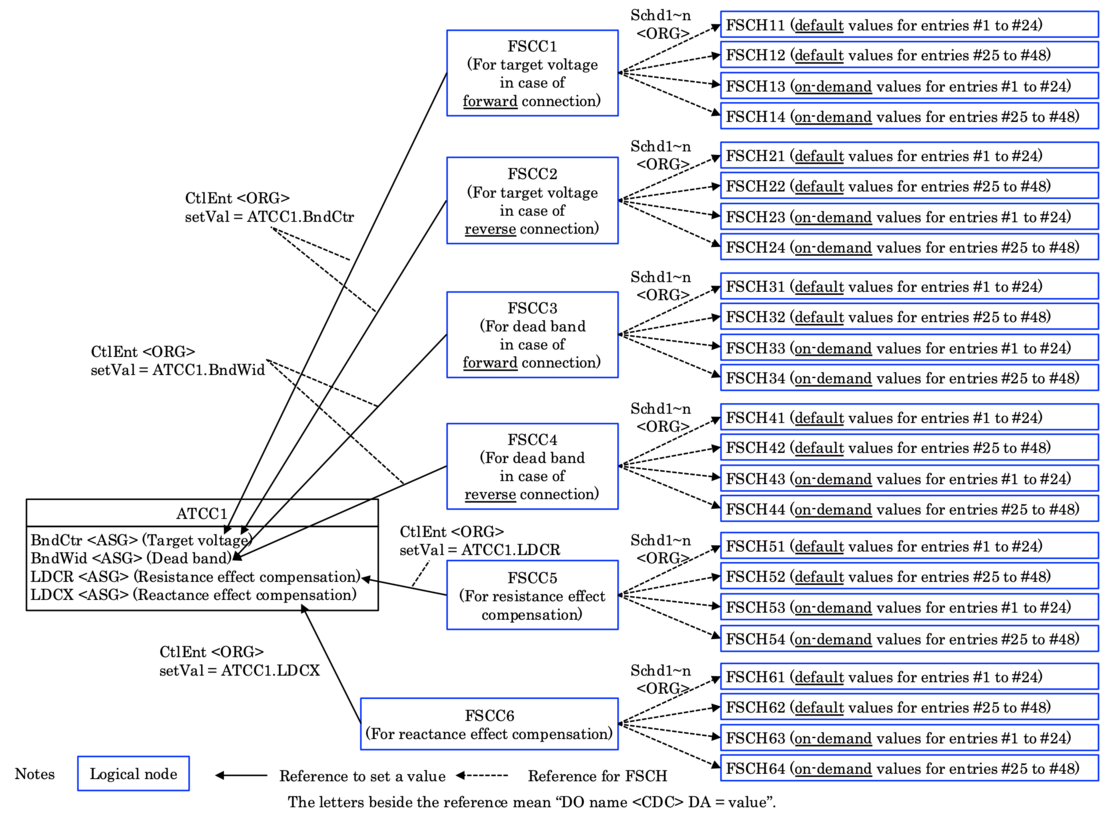
Figure 3 – The proposed combination of logical nodes to control SVR according to scheduled setting values.
FSCC instances are configured respectively for each DO (BndCtr, BndWid, LDCR and LDCX) in an ATCC used for SVR control. To handle switching of sets of scheduled values for the same DO according to SVR control mode, FSCC is also instantiated respectively for each control mode. For example, sets of scheduled values for the target voltage are switched according to the SVR connection to the substation, so that an FSCC instance referring to BndCtr of ATCC is configured for forward connection and another instance is done for reverse connection, as illustrated in Figure 3. Either of the FSCC instances will be activated according to the value representing the SVR connection. The same scheme is adopted for scheduling the dead band values that will be held in BndWid of ATCC.
3.2. Usage of ATCC
ATCC performs tap change control based on the setting values held by its own components (BndCtr, BndWid, LDCR and LDCX) for automatic mode. The proposed method adopts this function as defined in IEC 61850.
To apply ATCC to SVR control, the proposed method has extended the LN to have a new DO that is used to recognize and/or switch the direction of feeder connection, because the SVR control function needs to recognize which SVR terminal is on the side to a substation, as mentioned in Section 2.2. IEC 61850-7-4 assumes the use of ATCC as an automatic control function for the on-load tap changer (LTC) in a substation. Since the voltage control need not recognize the LTC connection, the ATCC does not have a DO to represent the latter. The added DO, named “SSFwd” meaning “substation forward”, is typed with SPC, namely the common data class to represent a single-point (true/false) control as defined in IEC 61850-7-3 [11]. If the stVal is true, the DO means that the connection of SVR is forward, i.e. Terminal A of SVR is connected to a substation. If not, the SVR connection is reverse. The DO value determines which FSCC instance actively manages the scheduled values for the target voltage and dead band respectively. The stVal of SSFwd can be set by manually defining the physical handle position of the field controller, or by the field controller itself, whereby feeder impedance is measured automatically. It can also be set by a master unit supervising the network topology of the distribution grid. In this case, the master unit sends a message to the field controller according to the procedures for SPC defined in IEC 61850-7-2 [12]. This amendment of the DO to ATCC is designed according to the rules set in IEC 61850-1-2 [13].
3.3. Usage of FSCH
The proposed method has two approaches for FSCH; one is how to instantiate FSCH and the other is how to set scheduled values held in FSCH. The following subsections explain the points respectively:
3.3.1 Instantiation of FSCH
In the proposed method, FSCH is instantiated according to the policies described below:
- One FSCH instance is assigned for a suitable duration to manage the scheduled value. In the case of the SVR control, an FSCH instance is assigned for 12 hours because setting values are calculated for the duration.
- The priority represented by SchdPrio of an FSCH instance for default values is set to 0 (the lowest).
- For an FSCH instance for default values, the start time represented by StrTm is set to be used periodically.
- An FSCH instance for on-demand values is arranged for each corresponding FSCH instance for default values.
- An FSCH instance for on-demand values holds the number of entries (NumEntr) and interval (SchdIntv) as the corresponding FSCH instance for default values. The start time (StrTm) of the FSCH instance for on-demand values has the same hour, minute and second as the corresponding example but does not recur periodically (one-time use).
- The priority of an FSCH instance for on-demand values is set to a positive integer, i.e. 1, 2, 3, … (higher priority). If multiple FSCH instances for on-demand values are used for the same duration, each of their priorities must differ.
- An FSCH instance for on-demand values is used once and just once when its setting values are updated. To achieve this, the start time of the FSCH instance shall be set to a proper activation time according to the policy “e” described above, whenever the scheduled values in the FSCH instance are updated.
Figure 4 depicts two pairs of FSCH instance for default values and one for on-demand values, with 24 entries, each including a 30-minute interval and start times set to 0:00 or 12:00. The first pair comprising FSCH11 and FSCH13 are set to start at 0:00 and the second, comprising FSCH12 and 14, are set to start at 12:00. FSCH11 and 12, instances for default values, are activated on a daily basis, while FSCH13 and 14, as instances for on-demand values, are activated on a designated day. An operator can use only FSCH13 or FSCH14 if it suffices for on-demand control. Even where using a different value for just one entry is preferable, the operator must use an FSCH instance for on-demand values with the number of entries, interval and set of hour, minute and second of the start time all unchanged. This is because the fixed number of entries, interval and set of hour, minute and second of the start time simplify the FSCC procedure, as described in Section 3.4. When the time set in StrTm of FSCH13 or FSCH14 comes around, the values held in the FSCH instance for on-demand values are used by FSCC according to priority. Note that FSCH instances can use weekdays for their periodical start time in a different pattern.

Figure 4 – The proposed combinations of FSCH instances
3.3.2 Setting scheduled values from client
Setting values are usually updated simultaneously for multiple entries. Since SetDataValues is a message defined in IEC 61850 for updating and conveying values of a single DO, multiple message exchanges are needed to update setting values represented by ValASGs in FSCH [12][14]. This means that the proposed method involves exchanging 24 messages to update all the ValASG in an FSCH instance. To simplify the update process, the proposed method uses DataSet, in which data attributes of multiple FSCH instances can be registered and SetDataSetValues to update the values for the data attributes using just a one-time message exchange. Updated values can then be reported to the master unit as a client to confirm the values because a SetDataSetValues response excludes the updated values. Figure 5 illustrates the procedures used to set scheduled values in the case of FSCH instances for default values.
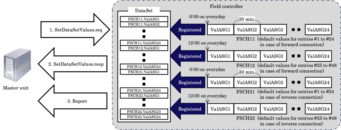
Figure 5 – Procedures to update scheduled values in the case of FSCH instances for default values
3.4. FSCC procedure for scheduling
General behaviors of FSCC for scheduling are described in IEC 61850-7-4 Ed. 2.1 but detailed procedures must be implemented during the system design phase. If no structured use of FSCH is provided, FSCC procedures could be complicated, which would hinder implementation. In the proposed method, the usage of FSCH as described in Section 3.3 facilitates the FSCC procedure.
Figure 6 is a UML activity diagram representing the FSCC procedure for scheduling in the proposed method. The procedure starts from the initial state shown as the black circle when Beh of FSCC is turned on, whereupon FSCC identifies which FSCH instance is used, obtains a value corresponding to the current time and sets it to the DO designated by CtlEnt. This processing continues until Beh of FSCC is turned off.
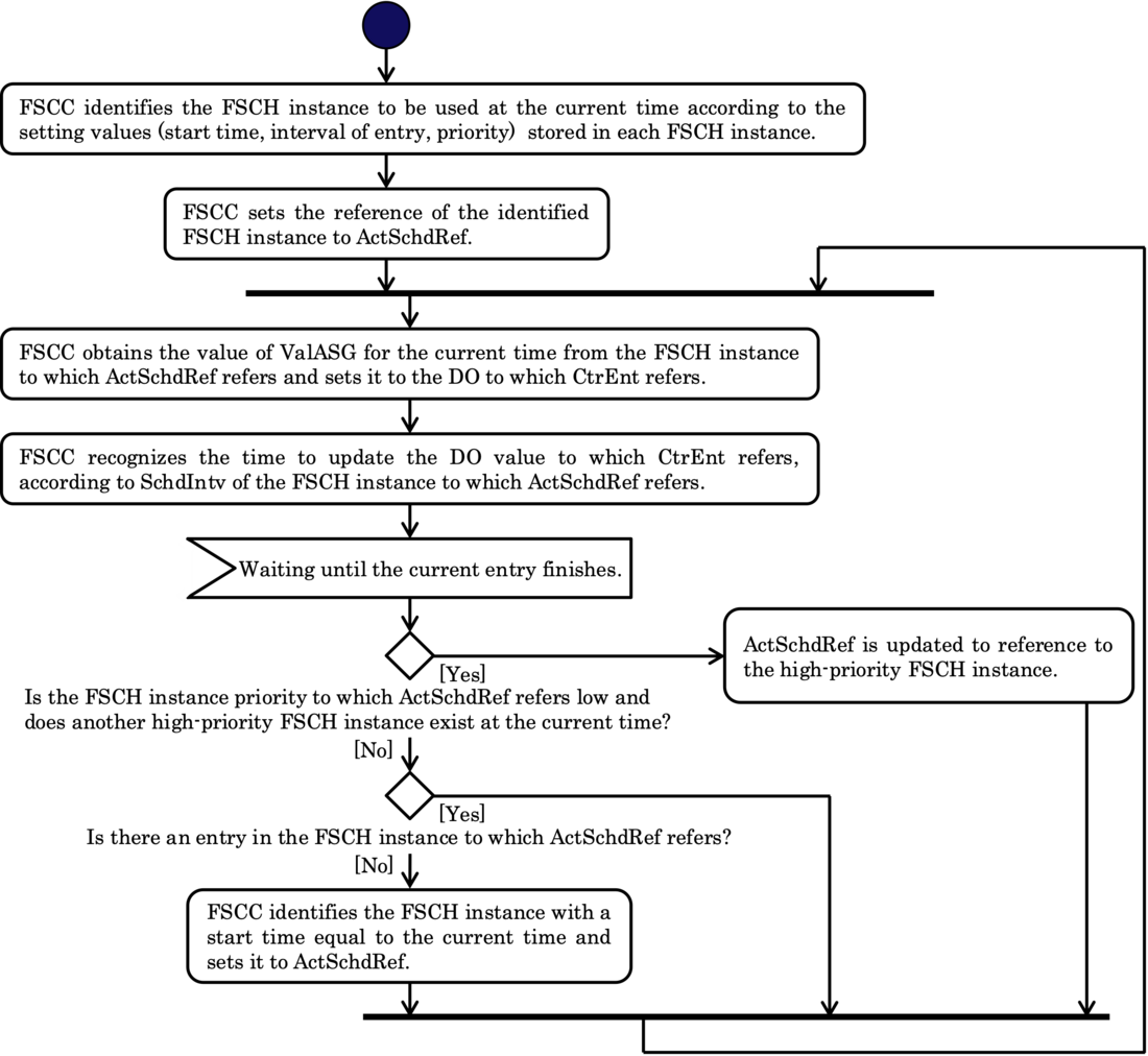
Figure 6 – FSCC procedure for scheduling in the proposed method
The conditions under which Beh of FSCC is turned on or off are determined by an SVR control scheme. In the case depicted in Figure 3, the Beh of FSCC1 and FSCC3 are turned off and those of FSCC2 and FSCC4 are turned on automatically when the SVR connection to be controlled is changed.
FSCC updates the value of the target DO when the active FSCH indicates the start time of next entry. If a master unit overrides the value onto the target DO such as BndCtr of ATCC, ATCC retains the value until the next updating time. This mechanism simplifies the FSCC procedure, because it eliminates the need to monitor the target value continuously.
4. Evaluations of the proposed method
The proposed method was implemented in a practical field controller for evaluation. This section describes the evaluation system and results and considers the feasibility of the proposed method, as well as its usability for other purposes.
4.1. Implementation of the evaluation system
Figure 7 outlines the evaluation system and Table IV lists its components. The master unit and field controller were connected via an L2 switch and an IP router. The L2 switch was used to distribute communication messages between the master unit and field controller to the PC for packet capture. The reason why the IP router was used is that communication networks for practical DAS comprise IP routers and the test conditions was configured to be equivalent to those of the practical network.
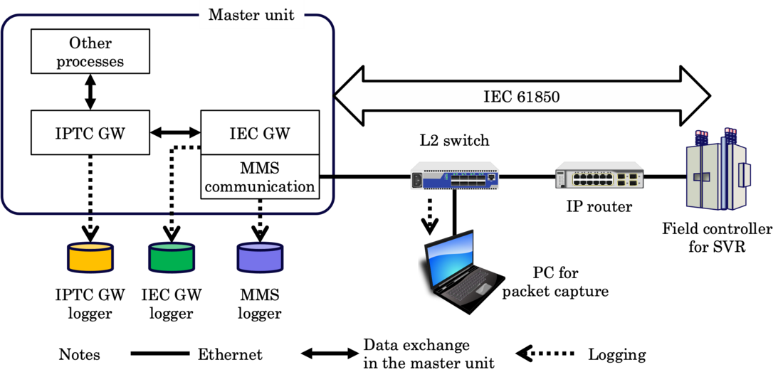
Figure 7 – Overview of the evaluation system
| Component | Subcomponent | Explanation |
|---|---|---|
Master unit
|
| It controls, configures and monitors SVR via the field controller. |
IPTC GW | It processes data and communications for the functions provided in the distribution automation system. | |
IEC GW | It plays the client role at IEC 61850 level (related to ACSI). | |
MMS communication | It sends/receives MMS protocol data units to/from the field controller. | |
Other processes | They are responsible for processes other than automation, such as human/machine interfaces. | |
Communication device | L2 switch | It provides a communication path to the PC for packet capture. |
IP router | It connects the master unit and field controller, like the | |
Field controller for SVR | Logical nodes for SVR control are installed in it according to the proposed method. It executes functions based on the LNs and communications to the master unit. | |
Logging device | IPTC GW logger | It stores logs obtained in the IPTC GW. |
IEC GW logger | It stores logs obtained in the IEC GW. | |
MMS logger | It stores logs obtained in MMS communication. | |
PC for packet capture | Wireshark is installed in the PC to capture IEC 61850 packets between the master unit and field controller. | |
The evaluation employed a field controller that was used in the practical DAS. In terms of the SVR operation mechanism, a simulator was used because the evaluation tests were carried out in a factory and arbitrary SVR operations were needed.
Communications between the master unit and field controller were measured during the evaluation tests, with messages captured and stored by Wireshark via packet capture software installed in the PC for packet capture. In addition, the activities of the processes in the master unit were recorded via the loggers illustrated in the figure.
4.2. Test procedures and results
The following communications were executed in the evaluation tests:
- A-1) Updating default values
- A-2) Updating on-demand values
- B) Remote switching between automatic and manual modes
- C-1) Transition to the next entry
- C-2) Tap change
Tests A-1 and A-2 were executed for updating values with requests and responses of SetDataSetValues and Report. Test B was for control with requests and responses of SelectWithValue, those of Operate and Report. Tests C-1 and C-2, meanwhile, were for process execution in the field controller and report of the execution results. Each elapsed processing period was measured based on the timestamps of messages stored in the MMS logger. Other logs and packet capture data were used to confirm the behavior of processes in the master unit or message exchanges between the master unit and field controller. Each test was executed just once due to time constraints, so that the following subsections show the measured elapsed time.
4.2.1 Results for updating values
In the tests, the setting values were updated in accordance with the procedures depicted in Figure 5. The field controller used in the tests provided FSCH instances managing values for 30-minute intervals for 12 hours and DataSet instances referring to the data attributes of some FSCH instances. The master unit used in the tests updated 290 data attributes for access to one of the DataSet instances.
Table V shows the elapsed time taken by the master unit to update default values and those on demand respectively. The elapsed time was measured from the moment when the master unit sent a SetDataSetValues request until the point when the master unit received a SetDataSetValues response in the case of “From request to response” period and when the master unit received a report from the field controller in the case of “From request to report” period. All results showed that the elapsed time for updating values was approximately two seconds in each case. It is conceivable that any variation in elapsed time would be mainly attributable to task scheduling in the field controller used in the tests.
| Category | Measured period | Elapsed time |
|---|---|---|
Updating default values | From request to response | 2.137 [s] |
From request to report | 2.237 [s] | |
Updating on-demand values | From request to response | 1.629 [s] |
From request to report | 1.981 [s] |
4.2.2 Results for switching between automatic and manual modes
The elapsed time for switching between automatic and manual modes was measured in the test to evaluate the behavior of control functions in the field controller in instances where the proposed method was implemented. Switching was selected because it is a procedure frequently used in practical SVR control operations.
A “select before operate” control model was adopted for measuring in the test and the elapsed time was measured from the time the master unit sent a SelectWithValue request. It stopped at the moments explained as follows:
- when the master unit received a SelectWithValue response in the case of “From select request to select response” period,
- when the master unit sent an Operate request in the case of “From select request to operate request” period,
- when the master unit received an Operate response in the case of “From select request to operate response” period,
- when the master unit received a report in the case of “From select request to report” period and
- when the master unit received a CommandTermination request in the case of “From select request to command termination” period.
The results showed that the control was completed in around two seconds as shown in Table VI.
| Measured period | Elapsed time |
|---|---|
| From select request to select response | 0.714 [s] |
| From select request to operate request | 0.715 [s] |
| From select request to operate response | 1.545 [s] |
| From select request to report | 1.945 [s] |
| From select request to command termination | 2.044 [s] |
4.2.3 Transition to the next entry and tap change
The transition to the next entry of the schedule and tap change was evaluated after reports triggered by autonomous control in the field controller were issued. During the test for the transition to the next entry, the master unit received a report notifying the transition 2.357 seconds after the field controller had processed the transition. In the test for tap change, the master unit properly received a report indicating a new tap position.
4.3. Considerations based on the results
4.3.1. Feasibility of the proposed method
The test results showed that almost all forms of processing, including communications, were properly completed in around two seconds. Since the performance scores meet the requirements for the distribution automation system, the field controller using the proposed method performs well enough for practical use. The productivity and installation of software with the proposed method is also good enough, given the solid practical track record of the field controller hardware.
Chubu Electric Power Grid Co. Inc., one of the ten major grid operators in Japan illustrated in Figure 9, has already installed over 1,000 SVRs with the field controller using the proposed method. Figure 8 depicts an SVR mounted on a pole in practical use, which includes the field controller using the proposed method. Passive optical networks dedicated to the DAS allow the master unit and field controller to exchange data. Neither the field controllers nor the physical communication paths have a redundant structure to limit costs. However, they perform sufficiently well to meet the reliability requirements. Of course, the field controller can work with other types of physical communication networks provided the bandwidth exceeds several Mbps.
The grid operator plans to install a total of around 9,000 SVRs with the field controller. Moreover, the ten major grid operators in Japan also plan to make IEC 61850-based specifications common to their DASs that include the proposed method for scheduled setting value management.
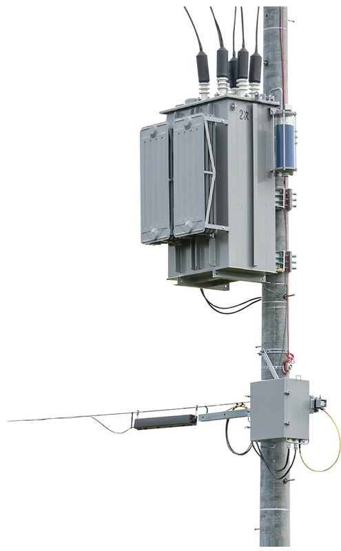
Figure 8 – SVR with the field controller installed on a pole in practical use
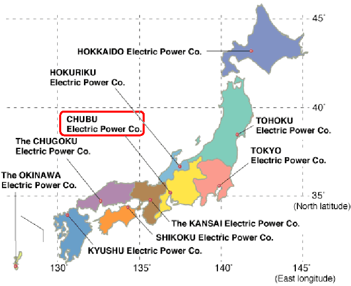
Figure 9 – Grid operators in Japan (cited from [16], the red rounded rectangle is added by the authors)
The test results and achievements indicate that the proposed method for setting value management is feasible for SVR control in the distribution automation system.
4.3.2. Usability for other purposes
Distribution automation systems owned and operated by other grid operators in Japan also usually adopt schemes using setting values to control SVR. These schemes may differ slightly in minor aspects, but the proposed method could be applied to them, given flexibilities about the number of entries and the interval per entry. In addition, the number of FSCH instances is almost the same as those in the distribution automation system having already used the proposed method. Even where setting values are dynamically changed, repeated updating by the master unit suffices to apply the dynamically changed values to SVR control and its performance could satisfy grid operator requirements. These circumstances suggest potential to implement and operate the proposed method in other distribution automation systems in Japan.
The proposed method can be applied to other control schemes based on scheduled values. For example, an on-load tap changer in a substation can also be controlled using the combination of logical nodes mentioned in Section 3. For DER (distributed energy resource) control, DPMC (power management capabilities) or an operational function LN as defined in IEC 61850-7-420 Ed. 2.0 [13] is used instead of ATCC and FSCC assigns a scheduled value to the logical node. No additional change is required to the proposed method, for which DER control should be applied. Such customized method could provide functionality such as an extension of the scope to curtail peak power generation and maintain the energy consumption level using batteries and controllable loads.
These considerations suggest an extension of the scope to use the proposed method for various kinds of control based on scheduled values in power systems. This advantage is not limited to automation systems in Japan, but also includes those anywhere worldwide. Accordingly, IEC 61850-based DASs and/or the proposed method are expected to be adopted for scheduled setting value management in many areas overseas.
5. Conclusions
This paper put forward a proposal in which the designated combination of FSCC, FSCH and ATCC is used to set value management in SVR control. It also described how the proposed method would be implemented in the field controller and showed the evaluation results of the method using the same. The results and considerations suggest that the proposed method would be practically feasible in terms of processing performance and general versatility.
The authors hope that this work will help facilitate the usage of logical nodes related to scheduling.
References
- OCCTO, Report on the Quality of Electricity Supply‐Data for Fiscal Year 2019, Feb. 2021. Available: https://www.occto.or.jp/en/information_disclosure/miscellaneous/files/211130_qualityofelectricity_2019.pdf
- JEPIC, The Electric Power Industry in Japan 2020, Mar. 2020. Available: https://www.jepic.or.jp/pub/pdf/epijJepic2020.pdf
- S. Rebennack, P. M. Pardalos and S. Haffner, “Step Voltage Regulator,” Handbook of Optimization in Electric Power Distribution Systems, Springer, 2020, Section 2.2.2.
- K. Matsuda, T. Futakami, K. Horikoshi, T. Seto, M. Watanabe, J. Murakoshi and R. Takahashi, “A Decision Method for LDC Parameters of a SVR and Voltage Control Algorithm using Measurement Data of a Distribution System,” IEEJ Transactions on Power and Energy, Vol. 132, No. 8, pp. 701–708, DOI: 10.1541/ieejpes.132.701, Aug. 2012.
- K. Murakami, S. Yoshizawa, H. Ishii, Y. Hayashi, H. Kondo, Y. Kanazawa, H. Nomura and T. Kajikawa, “Semicentralized voltage control method using SVR based on past voltage measurements in distribution network,” IEEJ Transactions on Electrical and Electronic Engineering, Vol. 15, No. 7, pp. 1032–1039, DOI: 10.1002/tee.23147, Jul. 2020
- A. Fujisawa and N. Kurokawa: “Oversea distribution automation system based on Japanese experience,” in Proc. IEEE/PES Transmission and Distribution Conference and Exhibition 2002, Vol. 2, pp. 1164–1169.
- D. Della Giustina, A. Dedè, A. A. de Sotomayor and F. Ramos, “Toward an adaptive protection system for the distribution grid using the IEC 61850,” In Proc 2015 IEEE International Conference on Industrial Technology (ICIT), pp. 2374–2378.
- Morder Intelligence: “Distribution Feeder Automation System Market – Growth, Trends, COVID-19 Impact and Forecasts (2021 – 2026),” 2021.
- Communication networks and systems for power utility automation – Part 7-4: Basic communication structure – Compatible logical node classes and data object classes, IEC 61750-7-4 Ed. 2.1, Feb. 2020.
- Communication networks and systems for power utility automation – Part 90-10: Models for scheduling, IEC TR 61850-90-10 Ed. 1.0, Oct. 2017.
- Communication networks and systems for power utility automation – Part 7-3: Basic communication structure – Common data classes, IEC 61850-7-3 Ed. 2.1, Feb. 2020.
- Communication networks and systems for power utility automation – Part 7-2: Basic information and communication structure – Abstract communication service interface (ACSI), IEC 61850-7-2 Ed. 2.1, Feb. 2020.
- Communication networks and systems for power utility automation – Part 1-2: Guidelines on extending IEC 61850, IEC TS 61850-1-2 Ed. 1.0, Jun. 2020.
- Communication networks and systems for power utility automation – Part 8-1: Specific communication service mapping (SCSM) – Mappings to MMS (ISO 9506-1 and ISO 9506-2) and to ISO/IEC 8802-3, IEC 61850-8-1 Ed. 2.1, Feb. 2020.
- Communication networks and systems for power utility automation – Part 7-420: Basic communication structure – Distributed energy resources and distribution automation logical nodes, IEC 61850-7-420 Ed. 2.0, Oct. 2021.
- The Federation of Electric Power Companies of Japan: “Service Areas by Company” https://www.fepc.or.jp/english/about_us/service_areas/ viewed on 27th February 2022.
Annex A. Outline of IEC 61850
This annex outlines IEC 61850 for the benefit of readers who may not be conversant with international standards to help them understand this paper. IEC 61850 specifies multiple aspects of power utility automation systems including information models, communications, configuration and conformance tests. It focuses on the information model referred to as a logical node because most parts in this paper are related to it.
A logical node models a portion of automation functions used to monitor, measure, control and/or protect primary equipment such as circuit breakers and power transformers. Many cases of functional implementation involve multiple logical nodes incorporating with each other to implement a function in an automation system. The name of the logical node comprises four capital letters, the first of which indicates a group of logical nodes. For example, “A” means a group for automatic control and “F” one for function block. The following three letters refer to a function modeled by the logical node. For example, “TTC” of “ATCC” means “tap changer controller”, “SCC” of “FSCC” means “schedule controller” and “SCH” of “FSCH” stands for “schedule”.
Each logical node has data objects that model parameters related to the logical node. A data object represents a set of parameters for monitoring, measuring, controlling and/or configuring status. One or more data objects are exchanged between logical nodes to execute a function.
Logical nodes and data objects are a kind of virtualized model that exist independently from the individual implementation of automation systems or control/protection devices. They provide users such as distribution system operators with an easy management scheme of consistent knowledge about power systems and automation systems. They also facilitate and ensure interoperability between various manufacturers’ control/protection devices.