Benchmarking of sealing systems of line composite insulators: ideas for innovative test methods
Authors
K. VARLI, S. STEEVENS, J. UNTERFINGER - Amprion, Germany
A. DERNFALK, I. GUTMAN, J. LUNDENGÅRD, P. SIDENVALL - I2G, Sweden

Summary
During the last decade, the market for overhead line composite insulators has increased rapidly, both in number of manufacturers and number of installed units in service. At the same time, some quality issues considered as being attributed to early generation of composite insulators, have been revealed even for the latest generation of composite insulators, e.g. poor adhesion of core/housing. Another sensitive part of the insulator design is the so-called triple point (where air and housing meet the metal end fitting). The insulator part around the triple point has to be properly designed and manufactured since a poor-quality sealing may influence the long-term performance of composite insulators and can result in damages leading to the failure of an insulator. At present, there is no reliable standard test to evaluate the quality of the different sealing methods. This issue became the driving force for this research project intended to summarize up-to-date knowledge of the different designs of fittings/sealings and propose and verify innovative test methods to evaluate the integrity of the sealing. The test programme consisted of seven sealing designs from six different manufacturers covering several different typical designs, which is representative for the existing sealing methods in the market. All tests resulted in different responses for different sealing designs, i.e. none of the tests resulted in “all passed” or “all failed”. It was also found that the complexity of the design of sealing does not necessarily improve the performance. Simpler designs showed good results as well. Finally, the corrosion and salt water boiling test proposed in this paper seems to be a promising scanning test for a quick evaluation of the sealing.
Keywords
sealing - adhesion, corrosion - salt water boiling - dye penetration test - salt fog test1. Introduction and goal
The market for line composite insulators is increasing rapidly considering both number of manufacturers and volume of installed insulators in service. However, some new quality issues may arise and are reflected by service cases. For example, poor adhesion of core/housing was recently revealed in service [1]-[4], which required relevant countermeasures in the form of new tests being developed and established [1], [5], [6]. However, with growing volume of production and attempts for low-cost production new quality problems might appear even for the experienced manufacturers. Another well-known sensitive area of the insulator is the so-called triple point (where air and housing meet the metal end fitting), see an example adopted from a draft of the revised standard IEC 62217 (general definitions and test methods for polymeric insulators) in Figure 1.
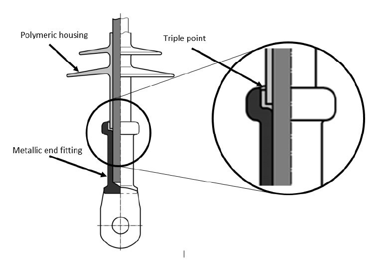
Figure 1 - Illustration of the triple point at the sealing of composite insulator
The part of the insulator close to the triple point should be properly manufactured since a poor-quality sealing can in the long-term result in damage leading to a failure of an insulator. A poor quality sealing can for example include air bubbles in the sealing itself or low adhesion between the sealing and other insulator components. These issues can lead to moisture penetration followed by corrosion which could even be accelerated by possible discharge activity. There are many different methods used by manufacturers for the sealing of the triple point. However, there is still no reliable standard test to evaluate the quality of the different sealing methods. This issue became the driving force for the research project described in this paper.
The goal of this paper is to summarize up-to-date knowledge on different designs and manufacturing techniques of sealings and to propose and verify different test methods to evaluate the quality of sealing methods. This is using a test programme of insulators from different manufacturers using different sealing methods.
2. Critical literature review
2.1. Basic types of fittings/sealings
The information available in the public domain on details of design and manufacturing of fittings and sealings is very limited. Normally, to obtain such information direct and detailed discussions with a manufacturer are required.
According to the definition, the end fitting is the integral component of a line insulator, intended to connect it to a supporting structure, or to a conductor. The fitting transfers the mechanical load to the glass fibre reinforced rod (core). End fittings can be made from galvanized steel, stainless steel, or aluminum. For overhead line insulators of transmission class voltage, end fittings are typically made from galvanized steel. From a mechanical perspective, the end fitting can be divided into two sub-parts: the connection zone, and the coupling design. The connection zone is where the mechanical load is transferred between the core and the end fitting. The coupling design is where the end fitting transfers the mechanical load to the accessories external to the composite insulator. There are three basic types of end fittings, i.e. cone type, wedge type and compression type. These three types are illustrated below in Figure 2 and are also mentioned in one of the first comprehensive books on composite insulators [7].
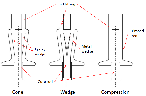
Figure 2 - Overviews of the three different basic end fitting design types [7]
The first two types (cone and wedge) were mostly used in the past and have several flaws which may influence the long-term performance of composite insulators by possible creation of cracks in the core. Most of the modern insulators are equipped with compression type end fittings. However, it is important that the end fitting is correctly crimped to the core rod, neither too tight (may introduce cracks) nor too loose (may slip off).
General summary on sealings can be found in [8] with three different sealing concepts illustrated in Figure 3. The authors recognized single and dual sealing systems. The internal sealing system can consist of one, two or even three different sealings [8]. The triple point can also be overmoulded by the housing (see the second example in Figure 3). If the insulator housing is sealed by overmoulding, an adhesive bond is used to secure tightness between the housing material and the fitting. The chemistry of such sealing is challenging because the composition of the upper zinc layer on the fitting determines the adhesion [8].
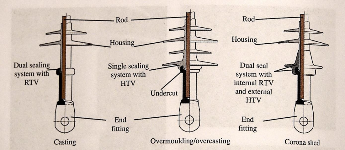
Figure 3 - Comparison of the main three sealing concepts [8]
Practical output from this part of the literature studies is that modern compression type fittings include many different types of sealings and most of them were practically considered and covered while creating a test programme.
2.2. Service experience of composite insulators related to sealings
The most comprehensive CIGRE-driven survey on service experience of overhead line composite insulators was published in 2010 [9], thus main data was collected more than 10 years ago. This survey included all types of insulators for voltage levels higher than 100 kV, i.e., suspension, tension, line post insulators and interphase spacers. The total number of insulators installed was at that time estimated at 700,000, and the volume of service experience (insulators multiplied by years) was 4,679,000, thus, the average service period was about 7 years. The score for the failed components of the insulators is presented in Figure 4. The insulator component which was predominantly reported to have failed is the rod (which might indicate failure mode called brittle fracture) followed by the rod/housing interface. Interface rod/metal can be considered to include sealing issues, thus counted in the “big five” of failure modes. Similar data from China included in CIGRE Green Book is presented in Figure 5 [10], where sealing is included in the “big six” of failure modes.
Practical output from this part of literature review is that although the sealing itself is not a dominating cause of failure, it can contribute to more frequent failures of other insulator components, such as e.g. interface rod/housing.
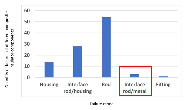
Figure 4 - Distribution of the number of failures types of different insulator components (adopted from [9]). Interface rod/metal is considered as including sealing issues
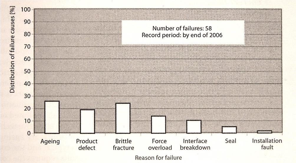
Figure 5 - Failure causes of composite insulators reported from China (adopted from [10])
2.3. Testing related to sealing
The IEC philosophy for the tests able to reveal changes in the design of sealing (“core/housing/end fitting interface”) is presented in Figure 6 adopted from the IEC standard 61109 for line insulators [11] and also referred to IEC standard 62217 [12] (general test methods for polymeric insulators). Besides pure mechanical tests, intended to check mechanical performance and assembly quality, only two electrical tests are required:
- Interface and connections of end-fittings (i.e. steep-front test after pre-stressing)
- Tracking and erosion test
More detailed analysis of these tests is provided in Sections 2.3.1 and 2.3.2.
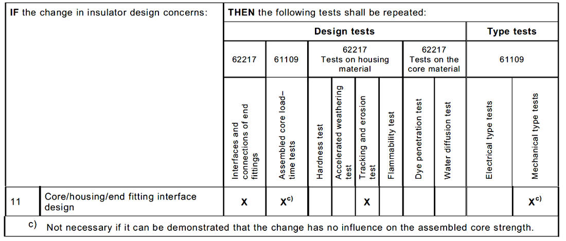
Figure 6 - Tests recommended to be carried out after change in design (adopted from [11])
2.3.1. Interface (steep-front) test
Details on interface test including steep-front test as main diagnostic test are provided in [11]. The steep-front test is performed after a series of pre-stressing by sudden load release under low temperature, thermal-mechanical cycle test while cycling at plus/minus temperatures, and water immersion (boiling in salt water). Different pre-stressing is theoretically intended to stress all interfaces of composite insulators including sealing. However, several insulators from different manufacturers tested in [13] passed the steep-front tests without problems despite having confirmed poor adhesion core/housing. These results allowed to conclude that steep-front test performed even at elevated steepness 3000 kV/μs (the standard steepness is 1000 kV/μs) is not able to reveal insulators with low adhesion core/housing [13] (poor adhesion was verified using other tests or by service experience). This conclusion may also be extended to the interfaces of sealing. A possible explanation is that originally (while developed in the 1970s) this test was intended to detect voids and intrusions in ceramic insulators and later (in the 1980s) was applied for composite insulators with the same purpose. Therefore, this test was not originally intended for the assessment of interfaces. However, steep-front test is still considered by the IEC as important to verify different weaknesses in insulators. Boling in salt water adopted from this test appeared to be an effective pre-stressing method influencing adhesion core/housing [1]. Therefore, a modification of this method was proposed to be included in evaluation in this paper.
2.3.2. Tracking and erosion test
The most common type of tracking and erosion test and at present the only test recommended by the IEC 61109 [11] is a 1,000 hour salt fog test. During this test the insulator is continuously affected by fine salt fog spray creating discharge activity stochastically spread along the insulator. The main intention of the test is to verify the material and profile, however other “weak” components of an insulator will also be tested, e.g. if the incorrect design leads to the concentration of discharge activity at some specific locations. Therefore, a modification of this test concentrated on sealing was proposed to be included in evaluation in this paper.
2.3.3. Summary on considerations for the creation of test matrix
At present there is no reliable standard or non-standard test to evaluate specifically the quality of sealings. The following indications from literature were considered for the creation of test matrix to be verified further:
- Revealed effectiveness of boiling in salt water led to the proposal to stress sealings by galvanic corrosion and boiling in salt water. This test is further called “Corrosion and boiling in salt water test”.
- Tracking and erosion test (salt fog test) might be effective. To accelerate the results by concentrating at the sealings, it is proposed to apply additional artificial contamination at the sealing to intensify discharge activity in this area.
- Additionally, a modified standard dye penetration test is proposed after the salt fog test as a diagnostic test method. The dye penetration test is known in the IEC 61109 [11], but it is only applied to verify the lack of open porosity in the core. However, this test was also used at limited scale for the evaluation of interface core/housing [14] and thus was considered for sealing.
- Electric field calculations are mentioned in [15] as an important part of the verification of electrical stresses at the interfaces. In this project electric field calculations are proposed to assess the electric field distribution in the area around the sealing, with the intention to reveal potential weaknesses with respect to possible ageing, especially in the presence of moisture.
If moisture is collected on the surface of sealings, it can lead to the specific type of ageing, called water drop induced corona ageing [14] If moisture penetrates the sealing, it amplifies the electric field stress. Thus, it is important to maintain relatively low electrical field stress in the area close to the sealing.
3. Test program
3.1. Test samples
Insulators with seven different sealing designs from six different manufacturers (from Europe, USA and China) were chosen and provided for the tests. The goal was to investigate as many different designs as possible. To study the different designs of fittings/sealings in detail, one end fitting of each type was cut open using an angle grinder. The dissection revealed the differences in the sealing methods of the samples provided for testing.
All insulators have used the three basic methods presented in Figure 3 in different ways and complexities, practical examples are shown in Figure 7. For example, two designs visually consisted of only mechanical sealing between the metal end fitting and the rubber housing, so the efficiency of the sealing should be dependent on the adhesion and mechanical pressure of the rubber towards the metal. Two designs accomplished the sealing with a special gel at the interfaces metal/rubber housing or metal/core. The last three designs used a mix of sealing with a gel and mechanical sealing. Another difference in designs was the overmoulding. There were three methods where the metal end fitting was overmoulded by the rubber, two of them are illustrated in figure 7. Furthermore, there were differences in the form of the metal end fitting including some complex designs.
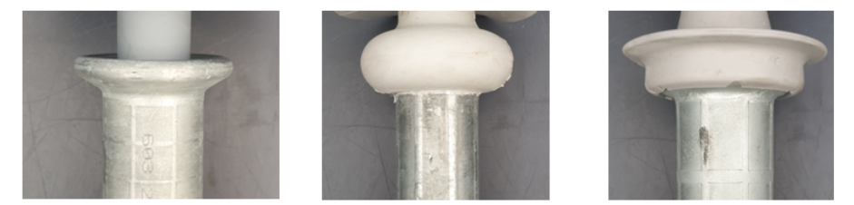
Figure 7 - Examples of different designs of fittings/sealings reflecting basic designs in Figure 3
3.2. Test methods
3.2.1. Corrosion and boiling in salt water
In the first part of this test, galvanic corrosion was intentionally initiated for pre-stressing since corrosion may deteriorate the impermeability of the sealing at the interface between end fitting and the housing. For this test, the end fitting was put into a metallic container filled with 10 liters of salt water. The salt water was a mixture of tap water and NaCl, with high salt concentration of 100 g/l. Galvanic corrosion was accomplished by applying a DC voltage of approximately 10 V between the metal end fitting (positive polarity) and the metallic container (negative polarity) for a time period of 2 h. In order to concentrate the current in the area of interest, i.e. at the interface between the metal end fitting and sealing/housing, the main part of the end fitting surface was electrically insulated from the surrounding water using plastic foil and insulating tape (see Figure 8). The area of the end fitting exposed to the salt water was in this way limited to 2,000 mm2. An additional electrode (negative polarity), in the form of a hose clamp, was also attached around the insulator close to the end fitting (10 – 15 mm away from it). This arrangement resulted in a DC current of 10 – 15 A.
An example of an end fitting prepared for pre-stressing by accelerated corrosion is shown in Figure 8, the set-up is presented in Figure 9. The exposed metal surface of the end fitting was wiped every 30 min in order to prevent a reduction of the current due to corrosion by-products covering the surface.
After corrosion test, the end fitting was cleaned and placed in new salt water and was boiled for 24 hours (second part of the test) in order to test the pre-stressed by galvanic corrosion samples for potential water penetration. After completed boiling, the end fitting was allowed to cool down to room temperature (in water) before close-up visual inspection for potential water penetration (signs of trapped water), corrosion, and any other kinds of deterioration.
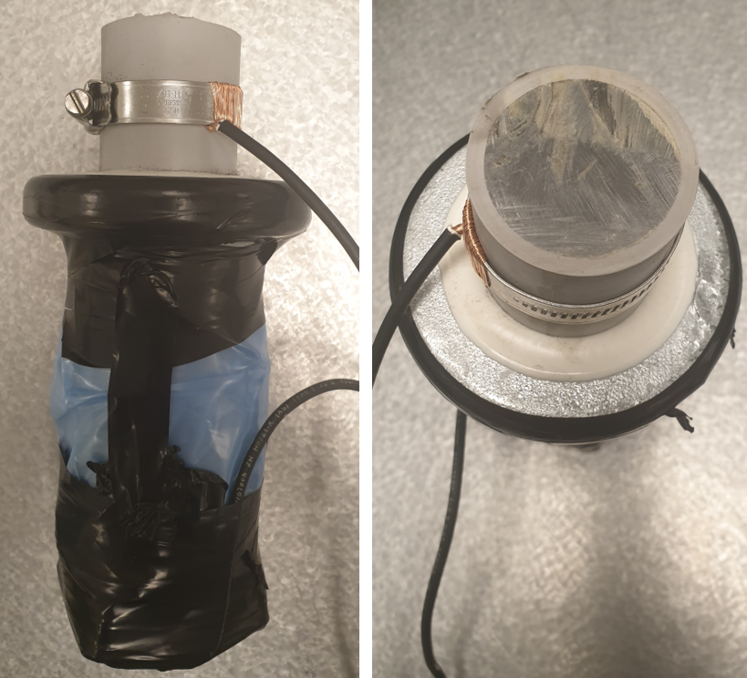
Figure 8 - End fitting prepared for pre-stressing by galvanic corrosion
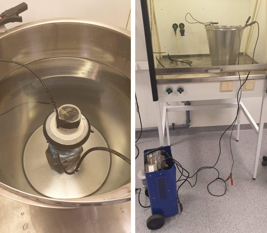
Figure 9 - End fitting in metallic container filled with salt water (left) - Container placed in fume hood and connected to power supply (right)
3.2.2. Modified 1,000 h tracking and erosion salt fog test
For this test, new samples were used. In order to expose the sealings to environmental stresses that can reflect natural stresses, it was decided to let the samples undergo a slightly modified 1,000 h salt fog test, described in the IEC 62217 section 9.3.3 [9].
Two test samples for each type of fitting were tested, e.g. the upper and the lower fitting. The preliminary aim was to test all samples at equal electric stress using approximately 200 mm creepage distance (reduced compared to the standard requirement of 500 – 800 mm in the IEC 62217). Due to practical reasons, a creepage distance of 207 mm was selected. This creepage was obtained by application of a ground electrode around the trunk at the appropriate position. In some cases the size of the sheds was slightly decreased by partial cutting of silicone rubber. This is to fit the ground electrode properly on the trunk at the appropriate position. The ground electrode was made from a stainless-steel cable tie. The creepage distance for this test is defined as the shortest distance along the insulating surface, from the bare metal on the fitting to the ground electrode.
Each sample was energized at the remaining intact end fitting and grounded at the applied electrode on the trunk by a cable for leakage current measurement. The test voltage was calculated according to the IEC 62217, i.e., equal to a specific creepage distance of 20.0 mm/kV, which provided 6 kV phase to ground test voltage for 207 mm of creepage. All test objects were mounted in a vertical position. The clearances between the test objects were less than specified in the standard, but also the creepage distance was only about a half of the typical values for testing of standard insulator samples. Thus, the deviation from the standard is not expected to have any impact on the results.
The salt fog precipitation was calibrated before the test start at several positions close to the sample locations. It was between
1.4 ml/h and 2.0 ml/h over a collecting area of 80 cm2. The standard specifies the requirement between 1.5 ml/h and 2.0 ml/h.
Due to the rather voluminous test set-up this slight deviation was considered as fully acceptable. The salinity of water was 10 kg/m3 throughout the test, this is slightly higher than the 8 kg/m3 specified as initial salt content of the water in the IEC 62217 for line insulators.
Just before starting the test, a thin layer of kaolin powder was applied to the silicone rubber housing and exposed sealings (over the whole test sample to be energized) in order to temporarily mask the hydrophobic properties. This was carried out according to CIGRE TB 555 [16]. After the tests, the samples were carefully inspected visually, looking after erosion, punctures, or any other possible deterioration.
3.2.3. Dye penetration of sealing
This additional diagnostic test was performed after the salt fog test to evaluate if the sealings were impenetrable after exposure to fog and leakage current activity. Therefore, this test was performed using the same test objects that were used for the 1,000 h salt fog test.
The sealings of the end fittings were immersed in dye penetration liquid (solution of 1% Astrazon BR 200 by weight in methanol) for 15 minutes. The dye penetration liquid and the duration were the same as described in the IEC 62217, clause 9.4.1. However, to accelerate the process of dye penetration, the pressure inside the end fitting was decreased by applying a vacuum. In all cases the pressure during the 15 minutes was less than 1.2 mbar and the actual pressure varied between different setups from 0.3 mbar to 1.2 mbar. This difference might be attributed to the tightness on the test equipment. The standard atmospheric pressure is
1,013 mbar, i.e. 1,000 times higher than used during the test. The vacuum pump (which was kept running through the test) was connected via an adapter mounted in the end fitting, in a threaded hole, drilled to approximately the center of the fibre glass core. Before the test, the samples were cut approximately 100 mm from the end fitting, and the sheds were also removed to easier fit the samples in the dye penetration liquid container. To avoid potential penetration of dye through the glass fibre cores (not intended in the present test), the cut surfaces of cores were covered by epoxy before the test. An example of a sample prepared for the dye penetration test is shown in Figure 10.
The test objects were dissected after the test and inspected visually to find if dye penetration liquid had penetrated the sealing interfaces. To allow for visual observation of the sealing and glass fibre core inside of the end fitting, the samples were cut perpendicular to the insulator axis close to the drilled hole and along the core. After cutting, the core and the sealing could be removed from the metal fitting for inspection.
This method was first verified in a special pre-test where a 0.7 mm drill was used to penetrate the sealing. In this case dye penetration liquid reached the core. For a similar sample, but with no special hole in the sealing, no traces of dye penetration liquid were found on the core inside the end fitting.
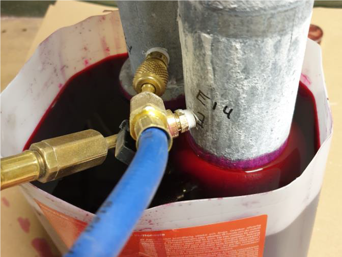
Figure 10 - Example of samples during the dye penetration test
3.2.4. 3D electric field calculations on sealings
In this part of the project electric field calculations were applied to assess the electric field distribution in the area around the sealing, with the intention to reveal any potential weaknesses. The fittings chosen for the investigations are rather different in design. For overhead line insulators, dimensioning electric field stresses are usually calculated using properly positioned grading rings around the end fittings and a realistic simulation of three-phase conductors and tower dimensions. In this case, maximum average electric stresses of 0.42 kV/mm along any 10 mm along the surface of housing and of 0.35 kV/mm for the triple point shall not be exceeded for composite insulators [14].
For the purpose of this project, the electric field stresses on the surface and inside the sealing were compared for the same maximum electric field on the end fitting or surface of housing. By this, the sensitivity of design for electric stress (higher or lower need of electric field grading) can be evaluated, considering, e.g.:
- Location of maximum electrical stress in relation to possible contamination and wetting
- Direction of electrical field at the sealing (along the sealing surface or away from it)
- Presence of many interfaces, which weaken the design from basic high-voltage knowledge point of view
- Possible presence of voids, which are complicated to reveal for the specific design, and which may weaken the sealing in the long term
3.2.4.1. Models and boundary conditions
The basic model was 2D rotational symmetric with one end fitting subjected to high potential (representing high voltage end).
The fibre glass rods were modelled as 800 mm long. The insulator model was positioned in the center of a sphere with a radius of 5 m. The upper half of the sphere was set to ground potential (0 V). The bottom half of the sphere was set to insulation boundary condition. To simulate properly all details of the dimensions of the end fittings, seal, rod, housing, etc. these parameters were carefully measured after the first dissection of the insulators. The high voltage boundary condition on the end fitting was in all calculations for comparative purposes adjusted to obtain 1.8 kV/mm maximum electric field on the end fitting or for overmoulded designs on the surface of the housing (this is typical electric stress criterion for the metal parts [17]). This also represents most cases, where an insulator passes the corona and RIV-test but with no consideration to electric fields along the surface of the housing or at the sealing (triple point or inside the sealing).
The material properties used for calculations are shown in Table 1. These are typical values based on previous experiences and literature data. Air has a breakdown strength of approximately 2.2 kV/mm and the solid materials (housing and sealing gels) have higher breakdown strengths. However, the breakdown strength is rather sensitive to contaminants (voids, water, dirt, etc.), which is why it is of the utmost importance to have controlled processes during manufacturing and assembly in order to avoid contaminants in the sensitive areas.
| Material | Relative permitivity |
|---|---|
| Air | 1 |
| Housing | 3 |
| Sealing | 2 |
| Glass fibre rod | 5 |
4. Test results
The results from all individual tests carried out are presented in the following sections.
4.1. Corrosion and boiling in salt water
After exposure to the galvanic corrosion and boiling, the sealings were inspected visually for signs of corrosion, trapped water, and any other kind of deterioration. To achieve this, the sealing and part of the rubber housing were removed to inspect the interface between the rubber housing and the end fitting. To compare the results, criteria for passing and not passing the test were proposed as follows:
- Absence of visual corrosion. This was the main criterion, which was characterized as “passed” in case of no corrosion (GREEN colour in Table 3) or “not passed” if corrosion was observed inside the end fitting (RED colour in Table 3).
- Subjectively evaluated level of adhesion while removing the sealing and part of the rubber housing for inspection. This was treated as an important criterion, characterized as “passed” when a good adhesion was revealed (GREEN colour in Table 3) or “not passed” if the adhesion at sealing interfaces was weak (RED colour in Table 3). The latter was typical when the rubber could be removed easily by hand.
- Absence of trapped water inside the sealing was considered as predecessor of corrosion. This was treated as an additional criterion, characterized as “passed” (no observation of water, GREEN colour in Table 3) or “accepted” (some traces of water observed, YELLOW colour in Table 3).
After the tests, corrosion was revealed inside the end fitting on three of seven sealing designs. For the same three designs a low adhesion at sealing interfaces was also detected. Apparently, a low adhesion leads to corrosion which can influence or even deteriorate the impermeability of the sealing at the interface between end fitting and the housing. For two of three designs low adhesion was also detected even on new fresh samples not subjected to testing. Based on these observations, the adhesion is considered as a manufacturing issue which the manufacturer should consider during the production. Also, the proposed test seems to have some accelerated ageing effect on the sealing revealing poorer designs. It is important to stress that different designs require the consideration of different issues. For example, if only mechanical sealing between the metal end fitting and the rubber housing is used, then the challenge is to achieve sufficient pressure and also ensure a completely clean area in order to avoid a creation of voids.
Considering trapped water, all designs passed the test. Even though traces of water could be observed on some samples, they never reached the core.
4.2. Modified 1,000 h salt fog test
The main criterion for passing this test were the results of the diagnostic dye penetration test which was performed after the
1,000 h salt fog test. However, the mean value of maximum current from two samples during the salt fog test was also treated as an additional criterion and was subjectively set to 300 mA. The test samples were placed in the chamber at two levels (heights). The leakage current on the actual lower end fitting of the insulator (hanging at higher level in the test set-up), was for all samples lower than on the actual upper end fitting (hanging at low level in the test set-up). The possible explanation could be that some of the salt water collected by the samples on top was running down on the sample below. Thus, this parameter was characterized as “passed” (GREEN in Table 3) or “accepted” (YELLOW in Table 3) based on the results on upper test object in the set-up, i.e. the lower end fitting of the actual insulator design.
In the event of a flashover the test would be considered as failed. However, during the 1,000 h salt fog test no flashovers occurred. The measured leakage currents are presented in Table 2 as maximum values recorded during the test.
| End fitting ID (lower/upper refers to position in service, not in the test) | Maximum leakage current (mA) |
|---|---|
| A, lower | 140 |
| A, upper | 380 |
| B, lower | 390 |
| B, upper | 570 |
| C, lower | 150 |
| C, upper | 430 |
| D, lower | 150 |
| D, upper | 200 |
| E, lower | 220 |
| E, upper | 450 |
| F, lower | 320 |
| F, upper | 420 |
| G, lower | 300 |
| G, upper | 630 |
The results of visual inspection were also treated as an additional criterion and are designated in Table 3 as “Visuals”. Traces of leakage current activity and salt deposit were revealed on all samples, but most of the sealings were visually unaffected at the end of the test. On two designs some narrow gaps between the sealing and the end fitting were observed. On one of these designs traces of erosion of sealing could also be observed.
4.3. Dye penetration of sealing
Visual observations were made on the cut sealings and fittings after the 1,000 h salt fog test. These visual observations were later combined with external visual observations of sealings presented in Section 4.2, providing input to the order of merit in Table 3. In this test the penetration of dye liquid all the way to the glass fibre core was considered as a failure criterion (RED colour), it was characterized as “passed” (GREEN in Table 3) in case of no remarks or “accepted” (YELLOW in Table 3) when slight deteriorations could be observed. In some samples the dye penetrated a few millimeters along sealing interfaces, but not all the way to the glass fibre core. Corrosion was observed on some of the non-galvanized surfaces. It was most pronounced for one design which used a fitting with the largest area without galvanizing protection.
4.4. 3D electric field calculations at sealing
The results of comparative electric field calculations were treated as additional criterion and thus were characterized as “passed” in case of no remarks (GREEN in Table 3) or “acceptable” (YELLOW in Table 3) if any remarks could be observed.
The results showed that in general the different end fitting and sealing designs are expected to perform rather well with respect to electric field stress, but with different specific features to be considered.
Typically, designs without overmoulded end fittings need a correctly located grading ring to protect the end fitting from initiating corona from the metal. This is a result of the flat top surface of the end fitting. The top part of the sealing can be more exposed to contamination and wetting (and therefore, possible discharge activity).
Overmoulded end fitting designs will reduce the electric field at the closest vicinity of the end fitting. This design is however characterized by a relatively high electric field at the covered electrode. This is not a result of poor design, but it does require that the surfaces (housing versus end fitting) have good contact and are free from voids and contaminants.
For sealing methods which use a gel, it is very important to avoid voids and any kinds of contaminants while filling. They may lead to internal discharge activity.
If the electric field at the surface of the housing is directed from the surface instead of along it, even high electric field levels are less severe from water induced corona point of view. If, at the triple point (air, upper sealing, end fitting), the electric field is pointed upwards, which is the same direction as the housing, the design might have issues with water induced corona at the triple point if not properly graded by an external electrode (grading ring). For such designs an external field grading is most probably needed even for lower voltage levels (maximum phase-to-phase operating voltage below 100 kV) to avoid water induced corona at the triple point and the lower part of the housing.
5. Discussion: effectiveness of proposed test intended to reveal design/manufacturing weakness of sealing
A Red-Yellow-Green (RYG) traffic light rating system is applied in Table 3, i.e. green colour illustrates sealings with good performance for the specific parameter, yellow colour illustrates acceptable performance, and red colour illustrates that this sealing did not pass the criterion for the specific parameter. Note that the results are based on investigations of only two insulators of each type, i.e. on very limited information. However, some valuable conclusions can be drawn from Table 3. It can be seen for none of the methods all samples have passed, or all have failed the tests. At the same time, some differences in the quality could be observed. While three designs have passed the corrosion and boiling test, four designs did not, thus forming two clusters. Therefore, some weaknesses in design/manufacturing could be revealed using this test.
All samples passed or were accepted in the ageing test including 1,000 h salt fog test and diagnostic dye penetration test. On all samples traces of leakage current activity and salt deposition were observed, but most of the sealings were visually unaffected. Narrow gaps between the sealing and the end fitting were observed at two designs of sealing. For one of these designs the gaps occurred due to erosion of the material in the salt fog chamber. For the other design, comparative examination of brand-new sample also revealed narrow gaps, thus this is treated as an original manufacturing issue.
Results of visual inspection after the dye penetration test revealed corrosion on some of the non-galvanized surfaces. This was mostly pronounced in one of the types which used a fitting with the largest area without galvanizing protection.
The ranking presented in Table 3 is not decisive, however, it provides an indication of response of the different designs of sealing to the tests intended to reveal weaknesses in design/manufacturing. Thus, this ranking might reflect a spread in the quality of combined design and manufacturing for the tested designs.
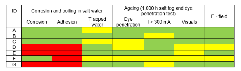
Table 3 - Results from all tests carried out
6. Conclusions
Literature study on sealings revealed the following:
- Detailed information on how manufacturers design the fittings and sealings is very limited in the public domain, especially regarding practical details (this requires direct discussions with a manufacturer). However, based on this literature study, the test programme of sealing designs investigated in this paper is considered representative and covers different typical designs.
- Analysis of service experience showed that information regarding issues related to sealings is limited but was mentioned in two surveys. Poor sealing in combination with other weakness, e.g. poor adhesion core/housing, would obviously reduce the life time of a composite insulator.
- Analysis of existing IEC tests intended to check in general interfaces of a composite insulator revealed that test methods proposed in this paper are relevant for further development. The existing test methods were then modified to increase the electrical and simulated climatic stresses just at the sealing.
Comprehensive tests of seven different designs of sealings revealed the following:
- All tests resulted in different response for different sealing designs, i.e. none of the tests resulted in “all passed” or “all failed”.
- Several criteria made possible to reveal two clusters (A – C and D – G) for tested designs. The difference between the clusters is clear and the ranking provides an indication of response of the different designs of sealing to the tests. Thus, this ranking might reflect a spread in the quality of design/manufacturing for the tested samples.
- Corrosion and salt water boiling test proposed in this report seems to be a promising scanning test for a quick evaluation of sealing. It might be considered for including in internal test procedures, however, it would require more verification and tuning before internal standardization is possible.
References
- I. Gutman, C. Ahlrot, P. Aparicio, A. Berlin, T. Condon, A. Dernfalk, J.-F. Goffinet, K. Halsan, K. Kleinekorte, J. Lundengård, M. Radosavljevic, P. Sidenvall, S. Steevens, K. Varli, K. Välimaa: “Development of Innovative Test Procedure for Evaluation of Adhesion of Core-Housing of Composite Insulators: from Root Cause of Failures in Service to Reproducible Test Procedure”, Cigré Science & Engineering, N. 20, February 2021, p.p. 171-182 : https://e-cigre.org/publication/cse020-cse-020
- I. Gutman, J. Lundengård, C. Ahlrot: “Need of standardized adhesion test for composite insulators: lessons learned from service experience”, 20th ISH-2017, Buenos Aires, Argentina, August 28 - September 01, 2017, paper 145: https://e-cigre.org/publication/ISH2017_145-need-of-standardized-adhesion-test-for-composite-insulators-lessons-learned-from-service-experience-and-testing
- M. Radosavljevic, I. Gutman, C. Ahlholm, P. Sidenvall: “Ageing and deterioration of composite post insulators exposed to high electric field in 220 kV and 400 kV switchyards in Swedish network”, 2017 CIGRE SC B3 Colloquium, Recife, Brazil, 18-20 September 2017
- I. Gutman, P. Sidenvall, T. Condon, P. Flynn, P. Shiel: “Evaluation of composite insulators with internal deterioration: lessons learned from service and after-service testing”, CIGRÉ Winnipeg 2017 International Colloquium & Exhibition, Winnipeg, Canada, September 30 - October 6, 2017, paper 142: https://e-cigre.org/publication/COLL_WIN_2017-sc-a3-b4--d1-colloquium-winnipeg-2017
- I. Gutman, A. Dernfalk, P. Sidenvall, J. Lundengård, C. Ahlrot, P. Aparicio, A. Berlin, T. Condon, J.-F. Goffinet, K. Halsan, M. Radosavljevic, K. Varli, K. Välimaa: “Rod to Housing Adhesion in Composite Insulators: Practical Evaluation in Collaboration with Utilities”, 2019 World Congress, Tucson, USA, 20-23 October 2019
- C. Ahlrot, P. Aparicio, A. Berlin, T. Condon, J.-F. Goffinet, I. Gutman, K. Halsan, M. Radosavljevic, K. Varli, K. Välimaa: “New test procedure intended to evaluate adhesion of core/housing interface of composite insulators”, CIGRE-2020, D1-303: https://e-cigre.org/publication/session2021d1-sessions-2020--2021-sc-d1-package
- R.S. Gorur, E.A. Cherney, J.T. Burnham: “Outdoor Insulators”, Ravi S. Gorur, Inc. Phoenix, Arizona, 1999
- K.O. Papailiou, F. Schmuck: “Silicone Composite Insulators”, Springer, 2013: https://link.springer.com/book/10.1007/978-3-642-15320-4
- CIGRE WG 22.03: “Worldwide Service Experience with Composite Insulators”, ELECTRA 191, August 2000, p.p. 27-43: https://e-cigre.org/publication/ELT_191_1-worldwide-service-experience-with-hv-composite-insulators
- K.O. Papailiou: “Overhead Lines”, CIGRE Green Book, Parisianou S.A., Athens, Greece, 2014: https://e-cigre.org/publication/GB-1-overhead-lines
- IEC 61109: “Insulators for overhead lines - Composite suspension and tension insulators for a.c. systems with a nominal voltage greater than 1000 V - Definitions, test methods and acceptance criteria”, Ed. 2.0, 2008-05
- IEC 62217: “Polymeric HV insulators for indoor and outdoor use - General definitions, test methods and acceptance criteria”, Ed. 2.0, 2012-09
- I. Gutman, A. Dernfalk, P. Sidenvall, J. Lundengård: “New Test to Reveal Level of Rod/Housing Adhesion for Composite Insulators”, 21st ISH-2019, Budapest, Hungary, August 26-30, 2019, paper 749
- I. Gutman, A. Dernfalk, J. Lundengård, P. Sidenvall, A. Deckwerth, K. Varli, M. Leonhardsberger, P. Trenz, K. Välimaa, P. Meyer, K. Halsan, M. Radosavljevic: “Test methods and criteria for validation of functional properties of composite insulators related to materials and interfaces”, CIGRE-2022, D1-828 (accepted for the publication)
- J. Lachman: “Lessons from 25 Years' Experience Testing Polymeric Insulators", 2019 World Congress, Tucson, USA, 20-23 October 2019
- CIGRE WG C4.303: “Artificial Pollution Test for Polymer Insulators Results of Round Robin Test”, TB 555, October 2013: https://e-cigre.org/publication/555-artificial-pollution-test-for-polymer-insulators---results-of-round-robin-test
- P. Sidenvall, I. Gutman, L. Carlshem, J. Bartsch, R. Kleveborn: “Development of the Water Drop Induced Corona WDIC Test Method for Composite Insulators”, IEEE Electrical Insulation Magazine, November/December 2015, Vol. 31, No. 6, p.p. 43-51