Grid code requirements in the UK for the connection of BESS in wind systems
Authors
W. BRICENO-VICENTE - Mott Macdonald limited

Summary
The ambitions to reach zero greenhouse gas emissions set in the UK by 2050 in the climate change act constitutes a major technical challenge for all participants. Thus, transmission and distribution networks are changing and adapting to a mix of technologies at all voltage levels of power generation and consumption. Future power networks will be dominated by wind and solar generation with the support of electrical energy storage (EES), especially of battery energy storage systems (BESS) in the presence of some remaining synchronous generation units of hydro, nuclear, and open cycle gas turbine (OCGT) fuelled by green sources. This paper discusses the advantages of BESS which has been demonstrated to be the most promising technology of EES to overcome several of the technical challenges for the integration of renewable energy systems (RES). A summary of the services provided by BESS technologies is presented, and the electrical control strategy employed. The BESS grid code acceptance requirements that BESS needs to comply with in the UK before its connection to the power network. A description of static and time-domain BESS study assessments is presented. The simulation results of a wind plant and BESS hybrid system are analyzed and recommendations are made according to the grid code dynamic compliance requirements.
Keywords
battery energy storage systems (BESS) - fault-ride through (FRT) capability - frequency control regulation - grid code requirements - voltage control regulationNomenclature
BESS battery energy storage systems
ES electrical energy storage
FACTS flexible AC transmission systems
FRT fault ride through
FSM frequency sensitive mode
GEP grid entry point
GFL grid following
GFM grid forming
HVDC high-voltage direct current
HES hydrogen energy storage
IBR inverter based resources
IWSES integrated wind, solar, and energy storage
LF load flow
FM limited frequency sensitive mode
Li-ion lithium-ion
LiCoO2 lithium-cobalt
PF power factor
PFC primary frequency control
PHS pumped hydroelectric storage
POC point of connection
PLL phase locked-loop
RES renewable energy resources
RoCoF rate of change of frequency
SFC secondary frequency control
STATCOM static synchronous compensator
SVC static VAR compensator
TEC total entry capacity
TFC Tertiary frequency control
VSG virtual synchronous generator
VSM virtual synchronous machine
WT wind turbine
1. Introduction
The increasing penetration of non-conventional renewable energy sources (RES) such as wind and solar, increases power oscillations and creates risks of instability of power network operations. The replacement of synchronous generation with RES units based on power electronics weakens AC networks’ stability and decreases the controllability of the network. One instability issue occurs in wind turbines (WTs) during three-phase faults with a higher error from the phase-locked loop (PLL) to track the voltage phase angle at the point of connection (POC) [1] which makes more complex the recovery after faults. Projections of the generation mix in the UK anticipate the integration of 100 GW of offshore wind power, 140 GW of BESS, 4.5 GW of nuclear power, and OCGTs fuelled with hydrogen used as a backup by 2035 [2]. The performance of RES plants wind and solar can be enhanced with the integration of electrical energy storage (ESS). Among ESS technologies BESS offers numerous advantages. It can support RES during periods of energy scarcity, increasing power injection quality, reducing power fluctuations, and decreasing the rate of utilization of conventional power plants with higher total operational costs, i.e. thermal power stations. At the same time, BESS can be used for peak shaving, load following, smoothing power fluctuations [3], increasing, stabilizing, and extending the availability of RES plants for longer periods of time. BESS can increase revenues of energy markets, discharging when the energy marginal costs are higher at peak hours, and charging during low demand hours [4]. BESS can serve as a backup during outages of distribution systems and emergencies feeding end clients of electrical substations. A variety of BESS applications, demonstration projects in micro-grids, distribution networks, smart grids, and virtual power plants from different countries are presented in [5].
This paper is structured as follows a review of BESS services provided to the grid is presented, the control strategy is reviewed, the grid code requirement according to the UK grid system operator is introduced, the case study and results of a wind-BESS are analyzed and the papers concludes with some specific remarks of the case study and the role of BESS and other technologies for the energy transition.
2. Grid services of BESS
The flexibility, ease of use, and reliability of BESS favor its connection in transmission and distribution networks. The reference [6] shows a comparative study of the different EES systems and BESS technologies in the past and projections of annualized costs ($/kW). BESS is made up of multiple cells containing a solid or liquid electrolyte that allows them to increase their power capability [7]. Nowadays lithium-ion batteries are the most used having a life cycle at 80% depth of discharge (DoD) of 3000 and lithium-cobalt batteries have the highest efficiency of 98.5%. The reference [8] makes a survey on the BESS technologies types, specifications such as efficiency, DoD, specific energy, and energy density that reflect efficiency concerning the use of space, market trends, advantages, and limitations. This section briefly discusses services provided by large BESS to enhance power system operations, applications of BESS in the UK and worldwide can be found in [9], [10].
Voltage control regulation
The main cause of voltage instability in the power networks is associated with reactive power fluctuations. The BESS can absorb and deliver reactive power, similar to functions currently performed in modern power systems by flexible AC transmission systems (FACTS), and static VAR compensator (SVC) to maintain the system voltage system stability [11]. The ability of BESS to operate in the four quadrants of active/reactive power implies that it can serve as a capacitor or reactor, and the fast response of the converter in the order of 20 ms allows BESS to enhance voltage stability according to their allocation [12]. When BESS is allocated near consumption centers can correct the power factor (PF) of end customers, and avoid operational violations and fee penalties. In addition, BESS can be used to reduce power losses in distribution networks. BESS can improve system stability by providing fast active power and reactive power support before the start-up of other generator units.
Frequency control regulation
Power system frequency stability occurs when all generation units rotate at the network speed of synchronism and the generation meets the demand at any time. However, the random nature of the load causes small power imbalances between the generation and demand that can lead to frequency instability issues lasting from a few seconds to even hours. Large disturbances such as loss of generation or demand can cause considerable frequency variations in the power system. Thus, three levels of frequency regulation control are implemented in the power systems which are differentiated in terms of their operating times and mechanisms involved in frequency regulation control defined below.
- Primary frequency control (PFC): When a fault occurs, it creates a sudden power imbalance occurs between generation and demand, causing rapid changes in the network frequency. The first corrective action is made through the generators’ spinning reserves and their proportional control speed regulation which allows a rapid response of active power generation during 10 to 30 seconds.
- Secondary frequency control (SFC): The generator setpoints are modified automatically or manually to maintain programmed power flows between areas of the system and prevent the disturbance from spreading, SFC time response varies from several 1 to 30 minutes.
- Tertiary frequency control (TFC): When the nominal frequency has been reached, it is necessary to achieve economic minimum and re-dispatched generation units to minimize generation marginal costs, TFC time response varies from 5 minutes to several hours [5].
The increasing connection of RES inverterbased resources (IBRs) reduces total system inertia affecting transient stability which will not be governed by the synchronous machine swing equation. Events such as disconnection of large generation units, loads, or system split without the incorporation of other technologies create changes in frequency excursions, rate of change of frequency (RoCoF), frequency nadir, and zenith greater than the designed values. The incorporation of RES in the UK has driven changes on the RoCoF which has been historically set to 0.125 Hz/s with no delay, recently updated to 1 Hz/s with a delay of 0.5 s [13] and nadir fixed to 49.5 Hz.
The challenges in low-inertia systems and solutions of frequency control regulation pre-event and post-event in the UK are discussed in [14]. For the pre-event period, a wide area motoring system is deployed to detect operational risks in real-time [14]. Several technologies can be deployed in the first-milliseconds post-events such as synchronous condensers (SynCons) and hybrid combinations with static synchronous compensator (STATCOM); grid forming (GFM) and virtual synchronous machines (VSM) inertia emulators and fast frequency response (FFR) services provided by flywheel energy storage (FES) as well other IBRs such as HVDC and BESS.
The connection of BESS can provide PFC [15] and SFC regulation. When there is an increase and decrease in the network frequency, the BESS can participate in PFC regulation by absorbing active power from the network (charging mode) and injecting active power to the network (discharging mode). To provide PFC regulation, the entire reserve of the BESS needs to be activated in 30 seconds and last up to 15 minutes. A comparison of various BESS technologies used for grid frequency support is summarized in [16].
Energy arbitrage
The power system operator in the UK performs economic dispatches on a 5-minute basis to exploit power plants in the most economical way considering the quality and safety restrictions of the system. The operating costs minimization of the energy bought and sold at marginal costs in deregulated markets allows the creation of a spot market. Hourly demand variations lead to increase marginal costs in peak hours and decrease off-peak hours. BESS can participate in energy arbitrage applications, frequency response services in day-ahead spot markets, a scheduling grid-tied and energy arbitrage study is presented in [17],[18]. ESS technologies can provide ancillary services to the grid including energy arbitrage, a techno-economic cost review of ESS is presented in [19]. For example, large pumped hydroelectric storage (PHS) can be combined with BESS and participate in energy markets on a daily basis, buying energy at low prices (charging) and selling energy (discharging) at higher prices [20]. A bottom-up approach of techno-economic and sensitivity analysis of system services in Ireland provided by BESS and the procurement process is described in [21].
Congestion management
BESS can be installed in the proximity of loads in distribution systems as an alternative to alleviate line congestion and avoid high investment costs related to line rating reinforcement and over-sizing. When a distribution line reaches its maximum thermal capacity during peak hours, the BESS can supply part of the demand by injecting active power for several hours daily. BESS can be installed in transmission systems to control the power flow congestion [9].
Black-start capability
When a total or partial failure occurs in the system is necessary to energize the power grid and support the connection of generating units and transmission lines [22]. The black start is a delicate and time-critical process where unbalanced loads with a dampening effect are very gradually connected to the grid and a converter and/or generator needs to keep the balance of active and reactive power and maintain the node voltages and frequency within strict limits. The operator needs to minimize the risk of collapse at all times. The BESS black start is related to the converter capability to energize generators from a cold state, for example, the time necessary to energize gas turbines ranges from 15 minutes to an hour, thus the discharging time of the BESS can last several hours. In this scenario, BESS can provide enough active and reactive power during black start energization.
3. Converter control strategy of BESS
The BESS converter strategy considered in this work is based on grid-following (GFL) which uses PLL to fix the current reference of the converter with the calculated terminal voltage angle of the IBR at POC. In consequence, the converter follows the network voltage and forms the active and reactive current references [23]. The GFL is used in classic wind and PV systems usually modeled as a current-controlled source. Other add-on features allow regulating active and reactive power independently using control gains for frequency-active power , and voltage-reactive power
. These main three features of GFL converters: PLL, P-f, and Q-v regulation are illustrated in figure 1. New control schemes have been explored to support GFL functionalities, such as virtual synchronous machine (VSM) [24], [25] that allows to include inertia emulation response.
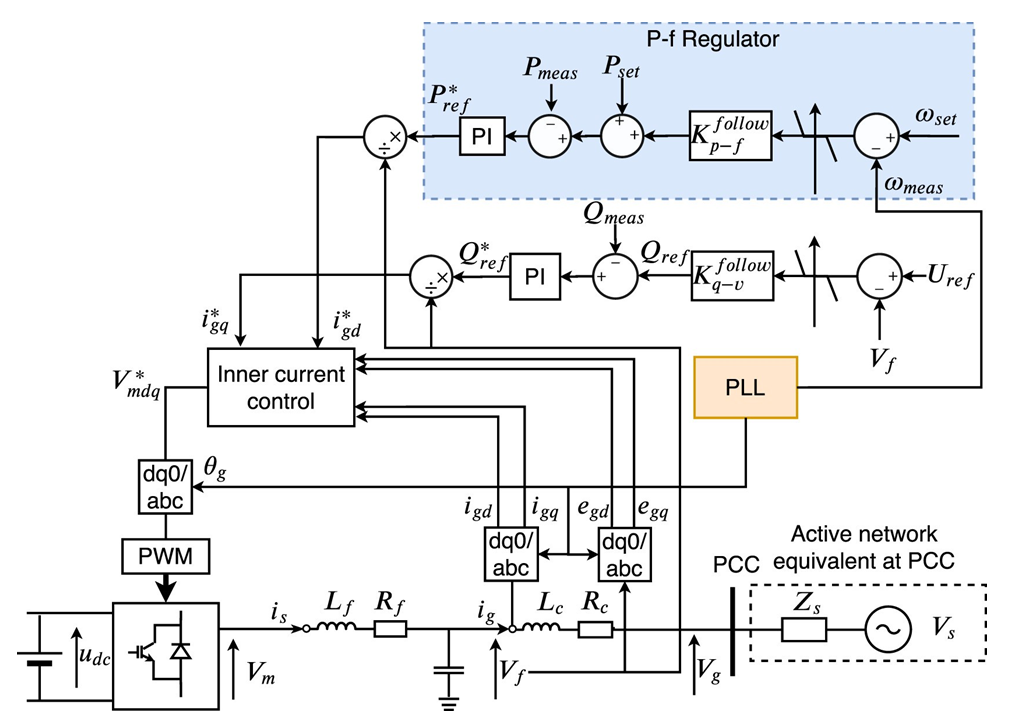
Figure 1 - GFL converter with grid-supporting mode [23]
The retirement of conventional generation units is driving the adoption of a grid-forming (GFM) control strategy, to replace the functionalities of synchronous machines such as inertia, grid voltage support, damping, and black start capability. GFM has been widely used in microgrid applications and has emerged as a solution at a great scale to fulfill the challenges of future power networks, enhancing services and security. It is expected that future BESS evolve to implement control features of GFM converters due to their implementation is less costly than for wind turbines according to manufactures [26], other technologies such as hybrid STATCOM (SVC) [27] have been adopted as part of GFM solutions. In GFM the PLL is no longer needed, instead, the frequency and voltage references are set according to a frequency droop using the exported active and reactive power. The control strategy of figure 2 is discussed in detail in [23] thus GFM converter is modeled as a voltage-controlled source. An open-box Pscad model with the main features of GFM is implemented using the IEEE 9 Bus system in [28]. The design, functionalities, and testing of GFM for power network applications are under study by manufacturers, transmission network operators, and other participants. Academics in the European project MIGRATE investigated several control schemes, power network requirements, and future service needs, the detailed documentation can be found in [29].
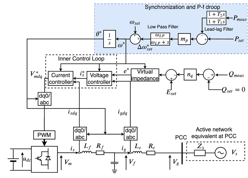
Figure 2 - GFM converter without PLL [23]
4. Grid code requirements of BESS
This section describes the current grid code requirements in the UK for BESS connection.
Reactive power capability
The BESS needs to fulfill the reactive power capability stated in the grid code [30] section ECC 6.3.2.4.4(c) at the MV grid entry point (GEP) presented in figure 3. When the BESS operates below its maximum capacity it needs to operate in the triangular shaded region between 50% and 20%. Additionally, the BESS must be capable of maintaining zero transfer of reactive power at the GEP for all active power output levels under steady-state voltage conditions according to section CC.6.3.2(b). The steady-state tolerance on reactive power transfer import and export must not be greater than 5% of the rated active power. The BESS must be capable of supplying rated active power at any point between the limits 0.95 PF lagging and leading at HV side of the transformer, from 132kV and above, defined in CC.6.3.2(c) for all active power output levels above 20%.
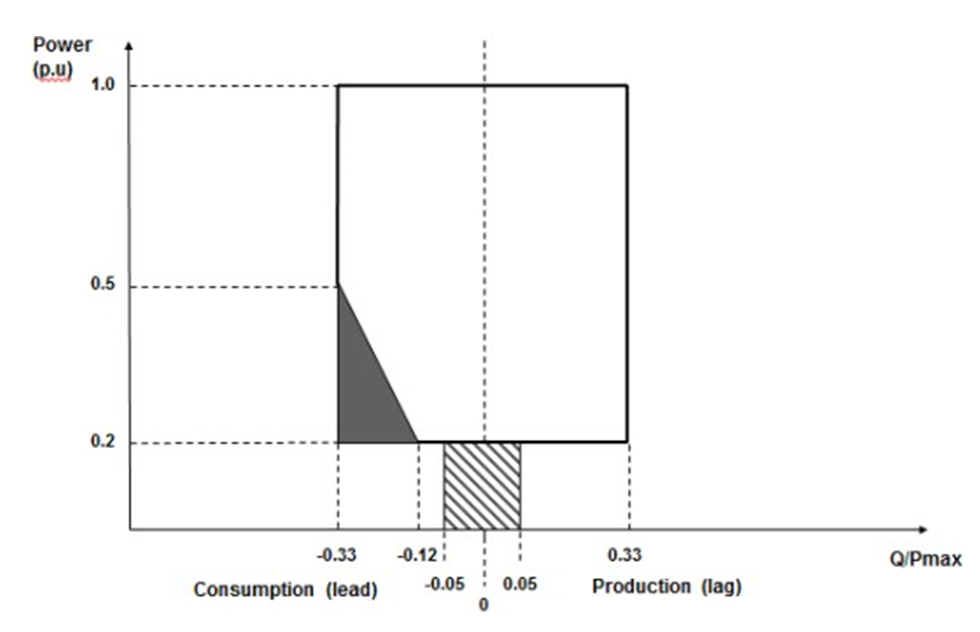
Figure 3 - Reactive power capability requirements at GEP [30]
The reactive power capability of the BESS in an integrated wind, solar, and energy storage (IWSES) park is obtained considering voltages at GEP from 0.9 to 1.1
p.u. in steps of 0.05 p.u. increasing the active power output of the WTGs and BESS in steps of 10% from 0 MW to the maximum active power capacity of the IWSES total entry capacity (TEC). The WTGs require to output maximum reactive power leading and lagging at GEP considering their power capability at the terminal voltage, the BESS must supply the rest of the reactive power.
Load flow (LF) studies
The purpose of LF studies is to determine the steadystate performance and behavior of the BESS and its interaction with the electrical network. The LF evaluates the voltage profile and loading of the electrical system in a dual or single configuration including the wind farm and when the BESS is either exporting or importing mode. The BESS hybrid system must consider a range of maximum and minimum voltage variations at POC of 1.0 10% according to admissible limits in clause ECC.6.1.4.1 of the grid code [30] at
0.95 leading and lagging. A sensitivity analysis of the voltage profile and circuit loading at POC needs to be carried out. In hybrid wind systems, WTGs normally operate under priority mode in power export, hence the BESS in export power mode is curtailed when the WTs are in operation. In the last situation, the most challenging operational scenario is when the BESS is set to export mode under 0.95 lagging PF. In distribution networks, the incorporation of STATCOM devices can control the voltage or reactive power flow across the boundary to the POC to comply with the reactive power requirements of the grid code. Several examples of wind-BESS topologies and STATCOM strategies are presented in [31].
Short-circuit levels
The BESS has a contribution to the short circuit levels. The IEC 60909 defines the recommendations for the short-circuit currents calculation. All equipment must withstand short circuit currents for one second without exceeding their capacity considering the capacity as the current carried in the closed position according to the IEC 62271-1. An adaptation of the IEC 60909 calculation is proposed in [32] for RES where the short circuit current contribution of power converter interfaced units is a current source from 1.5 to 2 times their nominal value.
Fault ride-through (FRT) capability
The BESS shall be capable of injecting maximum reactive current without exceeding its transient ratings, there is no specific requirement for a fast fault current injection. The BESS needs to remain connected to the network at the GEP for any fault type up to 140 ms in section ECC.6.3.15.1 [30]. The BESS must comply with FRT voltage profile characteristic against time at GEP of figure 4 considering rated active power output and maximum leading PF as it is specified in the section ECC.6.3.15.8. The BESS is required to remain transiently stable and connected to the system without tripping for balanced voltage dips applied in the HV side with a duration greater than 140 ms according to the voltage profile characteristic against time shown in figure 5.
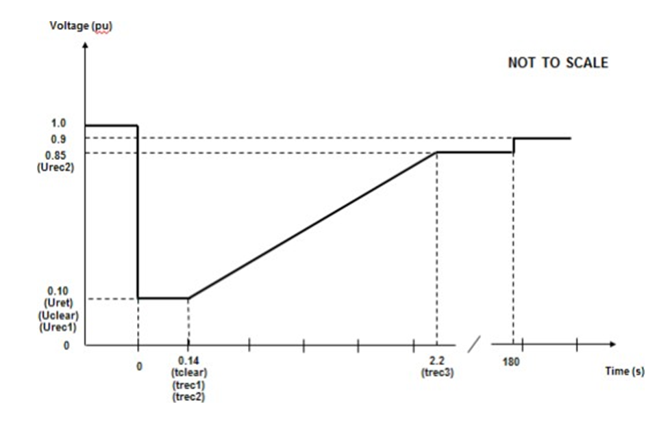
Figure 4 - FRT voltage limits in the GEP [30]
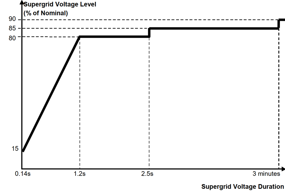
Figure 5 - FRT voltage limits in the TSO’s network [30]
The BESS needs to comply with the following FRT tests specified in the section CP.A.3.5 of the grid code:
- Symmetrical and asymmetrical faults applied during 140 ms on the MV at the GEP.
- a three-phase to earth fault.
- a phase to phase fault.
- a two-phase to earth fault.
- a single phase to earth fault.
- Symmetrical faults of variable duration on the nearest point of the HV power grid.
- 30% retained voltage during 0.384 s.
- 50% retained voltage during 0.71 s.
- 80% retained voltage during 2.5 s.
- 85% retained voltage during 180 s.
The BESS must restore the active power within 500 ms after the voltage recovery gets above 0.9 p.u. at the GEP.
Voltage control regulation
The BESS must provide a continuous automatic voltage regulation at GEP without causing instability issues according to section ECC.A.7.2.3.1 [30]. The BESS must comply with the dynamic performance in section ECP.A.3.4.1 considering the application of:
- one negative step in system voltage to cause a change in reactive power from zero to the maximum lagging value at rated active power output;
- one positive step in system voltage to cause a change in reactive power from zero to the maximum leading value at rated active power output;
- one voltage step of -2% while operating within 5% of the lagging reactive power limit;
- one voltage step of +2% while operating within 5% of the leading reactive power limit.
The step must be sufficiently large to require a change in the steady-state reactive power output from zero to the maximum leading or lagging value. The reactive power output response must commence within 0.2 s of the voltage step, and reach 90% within 1 s.
Frequency control regulation
The BESS must comply with the grid code frequency response requirements in clause ECC.6.3.7 [30]. The frequency response requirements include limited frequency sensitive mode at over frequency (LFSM-O), at under frequency (LFSM-U), frequency sensitive mode (FSM), and specific studies to demonstrate dynamic compliance requirements in frequency control.
LFSM at over frequency (LFSM-O)
The grid code specifies in the section ECC.6.3.7.1 that each BESS module must be capable of reducing the active power output in response to the frequency of the system rising above 50.4 Hz. The rate of change of the active power output must be at a minimum rate of 2% of output per 0.1 Hz deviation of the system frequency above 50.4 Hz (i.e. a droop of 10%) as shown in figure 6. The proportional reduction in active power must be achieved within 10 seconds of the time of the frequency increase above 50.4 Hz. The BESS shall be capable of initiating a power frequency response as short as possible. If the delay exceeds 2 s the variation must be justified by providing technical evidence.
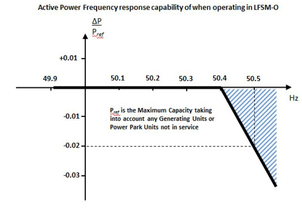
Figure 6 - LFSM-O Power-frequency response [30]
LFSM at underfrequency (LFSM-U)
The grid code requires in the section ECC.6.3.7.2 that each BESS module must be stable in LFSM-U and capable of increasing the active power output in response to the frequency of the system falling below 49.5 Hz. The grid code does not allow the BESS to operate in an inefficient mode to facilitate delivery of the LFSM-U response; any inherent capability (where available) should be delivered in the shortest time possible. The rate of change of the active power output must be at a minimum rate of 2% of output per 0.1 Hz deviation of the system frequency below 49.5 Hz (i.e. a droop of 10%) as shown in figure 7. The proportional increase in active power must be achieved for frequencies below 49.5 Hz. The BESS shall be capable of initiating a power frequency response with an initial delay that is as short as possible. If the delay exceeds 2 s the variation must be justified by providing technical evidence. The BESS shall be capable of providing a power increase up to its maximum capacity.
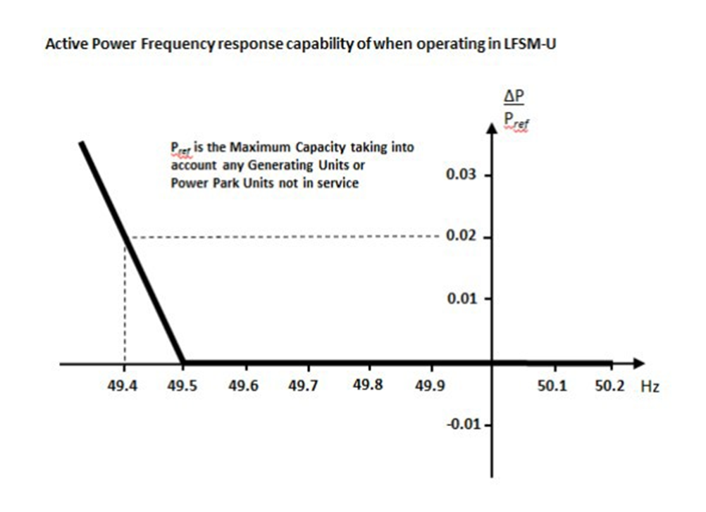
Figure 7 - LFSM-U Power-frequency requirement [30]
Frequency sensitive mode (FSM)
The grid code indicates in section ECC.6.3.7.3.1 that the BESS must be fitted with a fast-acting proportional frequency control device capable of providing frequency response under normal operational conditions. The frequency control device must operate over the entire operating range of active power output shown in figure 8. In the case of an event of a frequency step change, the BESS shall be capable of activating full and stable active power frequency response (without undue power oscillations), according to the performance characteristic of figure 9.
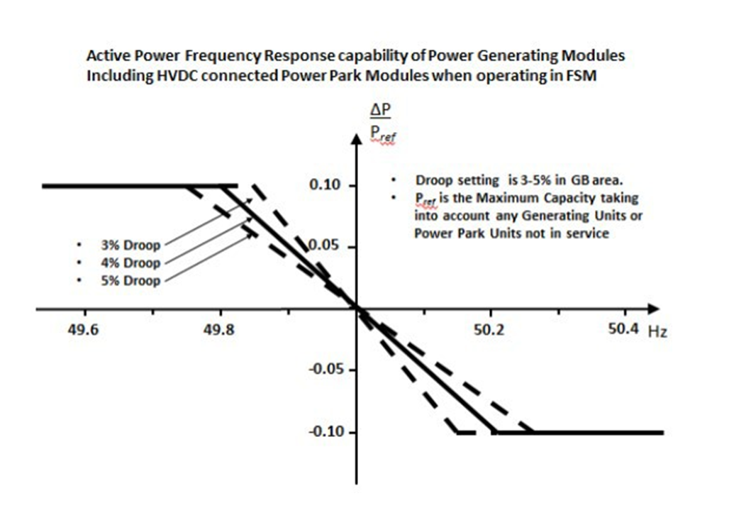
Figure 8 - FSM Power-frequency requirement [30]
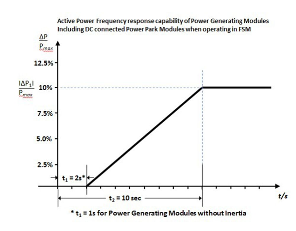
Figure 9 - FSM Power-frequency requirement [30]
The delay in the initial active power frequency response of the BESS shall not be greater than 1 s. If the generator cannot meet this requirement, technical evidence is required to demonstrate the time needed for the initial activation of the active power frequency response.
Frequency controller model verification
The grid code requires in the section ECP.A.3.7 compliance of the BESS converter ramp capability against time for low-frequency events of figure 10 when it operates at 80% of maximum capacity. The maximum deviation proposed for the frequency variation profile includes a negative step of 0.5 Hz and a positive step of 0.5 Hz both of which are within the LFSM range of frequency response insensitivity, when the BESS operates in LFSM must not activate power frequency response. Therefore, the BESS is assumed in FSM. When the physical test results become available, they are used to validate the results obtained from this study.
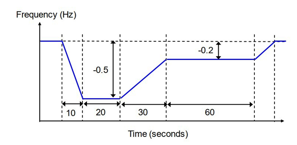
Figure 10 - Frequency controller verification requirement [30]
5. Study case results and discussion
Study case
The hybrid system under study is composed of a wind farm of 70 MVA and a BESS of 29 MVA. It represents an on-shore wind farm array located in Scotland of 35 WTs of 2.0 MW nominal power for each unit, connected through step-up transformers 33kV:0.69kV @ 2.35 MVA 9.5%. The study included the manufacturer models of the wind turbines and BESS, and every component was included in the simulation. The connection of a BESS is projected to improve the performance capability of the wind farm. The BESS is composed of 5 batteries of 5.8 MVA connected to the grid through step-up transformers 33kV:0.69kV @ 5.80 MVA 7%. Thus, the BESS is capable to support 29 MVA of the wind farm’s total capacity 70 MVA in periods of wind power scarcity. The hybrid system is connected in a radial configuration from the 400 kV TSO power grid at 50 Hz. Two step-down power transformers of 400kV:132kV @ 120 MVA 24.1% and 132kV:33kV @ 90 MVA 15% and overhead lines connect the GEP of the hybrid system to the grid. The single-line diagram in figure 11 shows the relevant information on the electrical parameters of the test system. The simulations considered electrical black-box models from manufacturers for each wind and BESS unit. The RMS simulation tool used to assess the studies was DigSilent Power Factory 2020SP1B(x64).
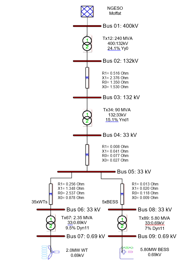
Figure 11 - Single-line diagram of the test network
The results presented in this section assess the aggregated dynamic performance and compliance of the BESS at GEP for FRT, voltage, and frequency regulation according to the grid code requirements. The plots results are shown in per unit having the system voltages, frequency, and nominal power of the BESS as bases. The static studies were performed previously and satisfied the grid code requirements. The reactive power capability complied with the operational limits in figure 3. The BESS less favorable operational condition for the power grid limit was verified, when the BESS absorbs reactive power and exports active power (discharges) at 0.95 lagging PF, which resulted in a depression of the bus voltages and an increase in the active current. The short-circuit study verified the contribution of the BESS to levels of short-circuit of the system and equipment under different fault types.
FRT capability
To verify the FRT capability and grid code compliance requirements, it is necessary to test variable balanced and unbalanced short-circuit conditions. The tests must include asymmetrical faults applied at the grid entry point (GEP) during 140 ms with maximum leading reactive power (inductive) from the BESS, as well as three-phase symmetrical faults applied at the nearest to the power grid for the different duration with zero reactive power from the BESS. All cases considered the maximum active power output from the BESS and minimum fault Thevenin equivalent level of the power grid.
The test simulation results of figures 12 and 13 correspond to the evaluation of a three-phase to earth fault applied on the MV GEP during 140 ms which is one of the most challenging fault conditions for the BESS controllers. When a three-phase fault to ground occurs at the BESS POC, the terminal voltage measured and used by the converter to calculate the power injection is low which creates instabilities in the PLL synchronization calculation method. The phenomenon in the PLL error causes undesired effects on the stability, especially in weak grids with short circuit ratios below 2.
The BESS voltage profile of the BESS at GEP shown in figure 12 is over the minimum limit grid code requirement plotted in the green dash line. It can be observed a post-fault voltage of 1.4 which indicates non-high voltage ride-through capability functionality to limit BESS over-voltages. The active power of the BESS of figure 13 is over the active power minimal limit of 90% MW requested by the grid code 500 ms after the fault clearance. All BESS FRT cases of unbalanced and balanced faults are compliant with the grid code FRT requirements.
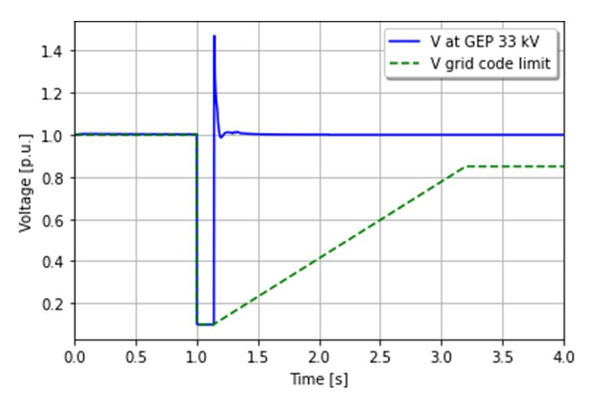
Figure 12 - Voltage profile compliance of the BESS for three-phase fault during 140 ms at GEP
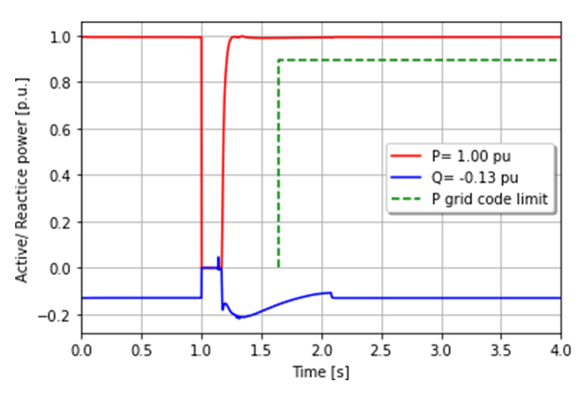
Figure 13 - Power compliance of the BESS for three-phase fault during 140 ms at GEP
Voltage regulation
The voltage-reactive power control regulation of the BESS is evaluated in a set of simulations according to the voltage step scenarios conditions previously outlined in the grid code requirements and summarized in table 1. The operational point specified in ECC.6.2.3.4 corresponds to 33% of the total MW at the GEP considering a voltage droop control setting of 4% and zero active power output. It is applied a voltage step to create a reactive power change from zero to the maximum reactive power injection and absorption. Cases A and B corresponded to voltage steps of -2.8% reaching 0.972 p.u. and +2.5% reaching 1.025 p.u. respectively.
For cases, C and D, it was applied a voltage step -/+2% at the terminal voltage when BESS operates in a power factor range of 5% lagging or leading.
The initial voltage response for all cases is within the time window required in clause ECC.A.7.2.3.1(i) of 200 ms from the time when the step change occurs until the maximum reactive power injection or absorption is reached. The BESS achieves a stable response within 2 s. The voltage step applied is plotted in solid lines in figures 14 and 15, the reactive power output response of the BESS in dashed lines with the same color indicates the grid code requirement compliance. The BESS achieves in all cases 90% of the total reactive power output change within 1 s after the occurrence of the voltage step change required in ECC.A.7.2.3.1.(ii) Section of the grid code. The simulation results obtained are summarized in table 1.
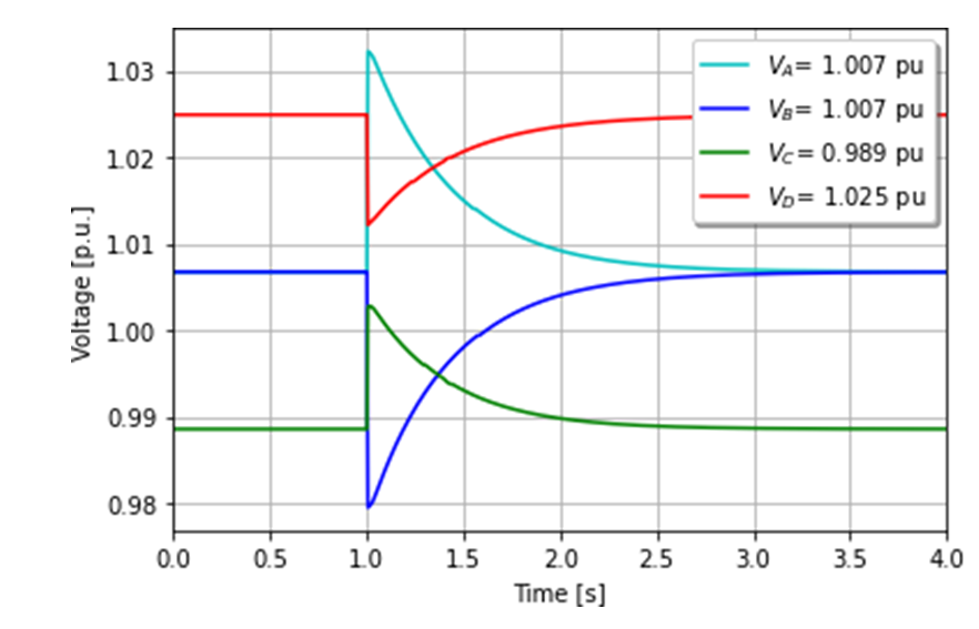
Figure 14 - Voltage profile of the BESS for voltage control regulation compliance test
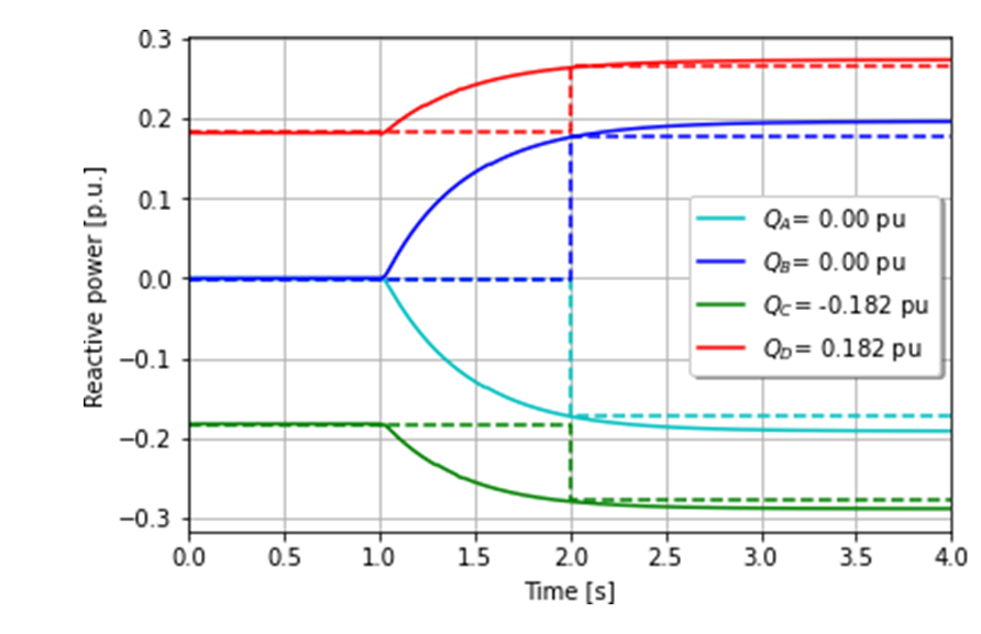
Figure 15 - Reactive power of the BESS for voltage control regulation compliance test
| Case | V:VStep[p.u.] | Q:QStep[p.u.] | Qlimit[p.u.] |
|---|---|---|---|
A | 1.007 : 1.032 | 0.000 : -0.182 | -0.192 |
B | 1.007 : 0.979 | 0.000 : 0.176 | 0.196 |
C | 0.989 : 1.003 | -0.182 : -0.278 | -0.289 |
D | 1.025 : 1.012 | 0.182 : 0.273 | 0.264 |
Frequency regulation
The frequency response capability in LFSM-O and LFSM-U are verified by applying frequency change steps of ± 0.008, ± 0.012, and ± 0.016 p.u. considering 50 Hz as base. The BESS controllers are set to 4% droop of active power frequency response. For LFSM-O and LFSM-U tests, the BESS is assumed to operate at 100% and 90% of nominal active power to provide frequency support. The grid code does not provide specific guidance in the compliance process to select the export output level of the BESS. The figure 16 indicates the frequency steps applied to the BESS to verify the active power response grid compliance in LFSM-O and LFSM-U shown in 17. The system frequency 50 Hz and the BESS rated power are considered as the bases for the plots. The results of frequency variations and active power response are summarized in table 2. According to grid code requirements in figures 6 and 7, the BESS in LFSM must not deliver addi tional power from the steady-state condition (zero active power variation) to the grid inside the frequency band from 0.990 to 1.008 in per unit and for frequency values outside of the band the slope rate active power-frequency must be inferior to -10 p.u. The BESS adapted its active power output without oscillations to respond to the frequency changes in LFSM. The results table 2 show that the points O1 and U1 show no active power variation and for the rest of the frequency variations the active power-frequency slope was inferior to the maximum limit of -10 p.u. allowed by the grid code. In consequence, all the test points are compliant with the LFSM-O and LFSM-U requirements. The dynamic frequency response for LFSM-O in figure 17 is activated within less than 70 ms delivering full power output variation within 150 ms, which complies with the speed response attained in the grid code clause ECC.6.7.1.2 (iii) of 2 s. The frequency response for LFSM-U is activated within less than 50 ms delivering full power output variation within 100 ms, complying with the speed of the response of the grid code in clause ECC.6.7.2.2 (ii) of 2 s.
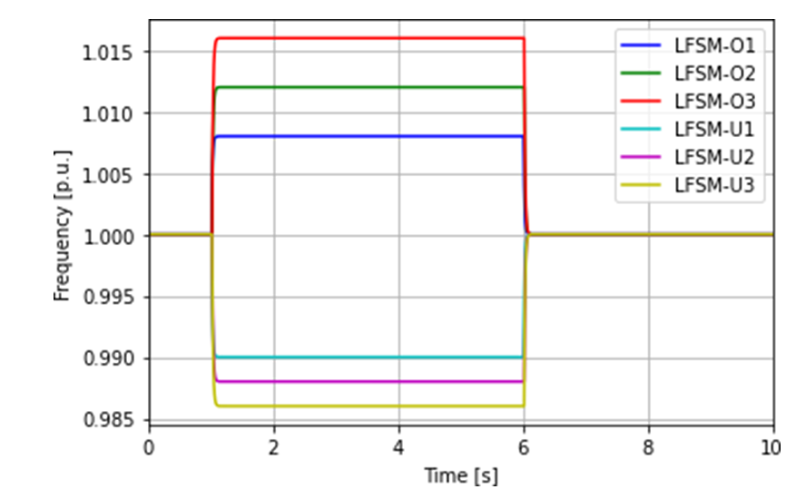
Figure 16 - Frequency profile of BESS for LFSM-O and LFSM-U compliance test
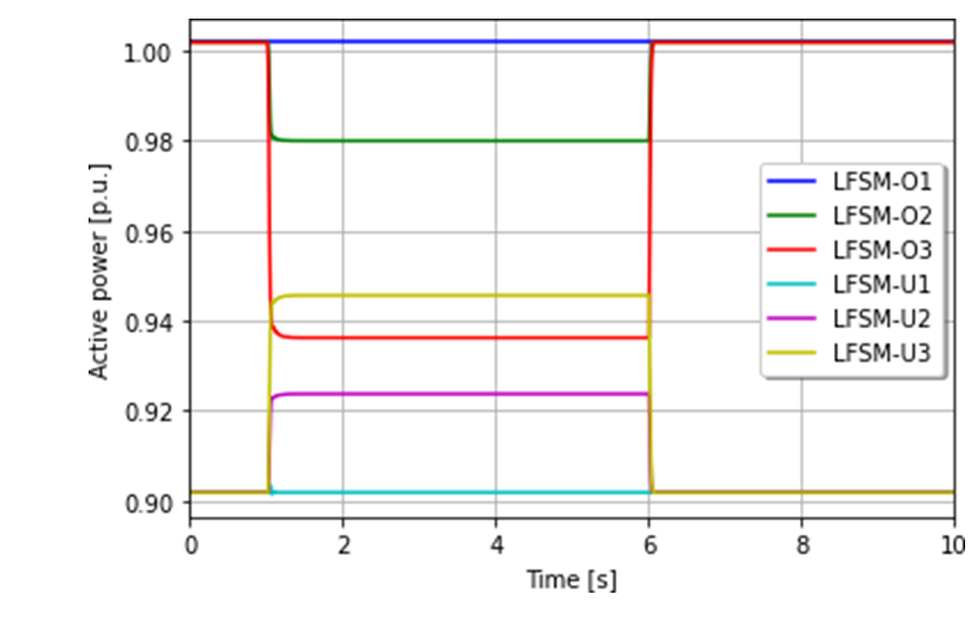
Figure 17 - Active power variation of BESS for LFSM-O and LFSM-U regulation compliance test
| Case | F:FStep[p.u.] | P:PStep[p.u.] | ∆P/∆F |
|---|---|---|---|
LFSM-O1 | 1.000 : 1.008 | 1.000 : 1.000 | 0.000 |
LFSM-O2 | 1.000 : 1.012 | 1.000 : 0.980 | -1.666 |
LFSM-O3 | 1.000 : 1.016 | 1.000 : 0.936 | -4.000 |
LFSM-U1 | 1.000 : 0.990 | 0.902 : 0.902 | 0.000 |
LFSM-U2 | 1.000 : 0.988 | 0.902 : 0.924 | -1.833 |
LFSM-U3 | 1.000 : 0.986 | 0.902 : 0.946 | -3.143 |
The frequency response capability in FSM is tested by applying frequency steps of ± 0.002, ± 0.004, ± 0.01, and ± 0.03 p.u. considering 50 Hz as the base, with the BESS operating at 90% of nominal power. The frequency steps and active power response in FSM are shown in figures 18 and 19 which are summarized in table 3. When the BESS operates in FSM inside a frequency band from 0.990 to 1.008 p.u. the maximum active power-frequency slope rate is -25 p.u. using a 4% droop characteristic according to figure For sudden changes from nominal frequency outside the FSM band, the BESS will have a limited active power response below 10% of the nominal active power. When frequency excursions occur outside the FSM band, the BESS active power response must remain constant. The BESS changed its active power output without oscillations to respond to the frequency variations in FSM and LFSM which is also verified in the ramping capability tests. The simulation results are summarized in table 3 with the calculation of the active power-frequency slope for frequency steps from the nominal frequency. The case FSM-O2 exceeds the maximum active power-frequency slope allowed of -25 failing to comply with the code clause ECC.6.3.7.2.2. (i). The plots show that active power frequency-time response is activated rapidly within less than 20-30 ms, with full active power change deployed within 1 s without power oscillations which complies with the requirements outlined in the clause ECC.6.3.7.3.3. (iii) of 2 s in figure 8. In order to achieve compliance with the slope rate of FSM-O2 the BESS control variables must be re-tuned in cooperation with the manufacturer and verify the grid code compliance before the connection to the grid.
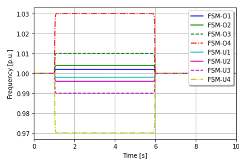
Figure 18 - Frequency profile of BESS for FSM-O and FSM-U compliance test
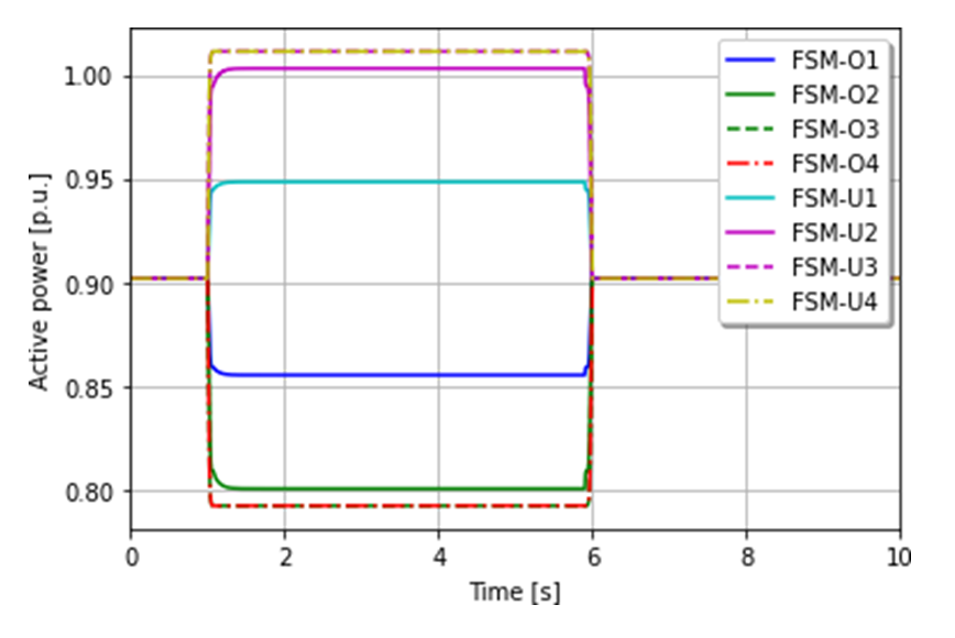
Figure 19 - Active power variation of BESS for FSM-O and FSM-U regulation compliance test
| Case | F:FStep[p.u.] | P:PStep[p.u.] | ∆P/∆F |
|---|---|---|---|
FSM-O1 | 1.000 : 1.002 | 0.905 : 0.855 | -25.000 |
FSM-O2 | 1.000 : 1.004 | 0.905 : 0.801 | -26.000 |
FSM-O3 | 1.000 : 1.010 | 0.905 : 0.792 | -11.300 |
FSM-O4 | 1.000 : 1.030 | 0.905 : 0.792 | -3.767 |
FSM-U1 | 1.000 : 0.998 | 0.905 : 0.948 | -21.500 |
FSM-U2 | 1.000 : 0.996 | 0.905 : 1.003 | -24.500 |
FSM-U3 | 1.000 : 0.990 | 0.905 : 1.011 | -10.600 |
FSM-U4 | 1.000 : 0.970 | 0.905 : 1.011 | -3.533 |
The simulation results of the BESS converter ramping capability in FSM are shown in figure 20 and summarized in table 4. The BESS instantaneously activates the active power frequency response upon the commencement of negative and positive frequency ramps deviation, which is in line with the performance characteristic limits outlined in the grid code clause ECC.6.3.7.3.3. (i). The BESS converter maintains a stable active power output throughout the periods when the frequency is flat. The simulation results must be validated with measurements of the converter to complete the validation process of the converter ramping capability performance. The IEC 61400-27-2 [33] describes the methodology to validate wind turbine models base on playback of the measured signals feed in simulation models to evaluate the accuracy of the model with the real hardware. The IEC recommendations can be followed in the validation process of the BESS frequency control with a minimum time step resolution of 0.25 cycles.
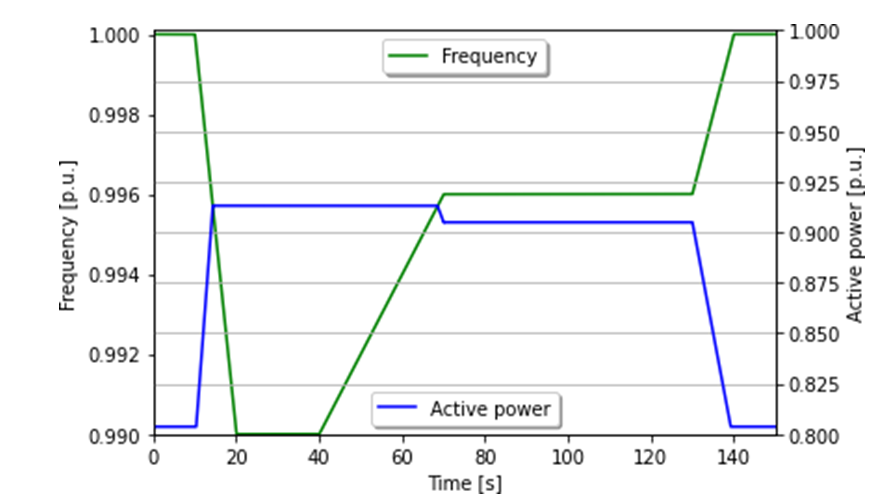
Figure 20 - Converter verification of BESS in FSM
| t1:t2 [s] | F1:F2 [p.u.] | P1:P2 [p.u.] |
|---|---|---|
10:20 | 1.000 : 0.990 | 0.804 : 0.913 |
40:70 | 0.990 : 1.004 | 0.913 : 0.905 |
130:140 | 0.996 : 1.000 | 0.905 : 0.804 |
6. Conclusion
The connection BESS in IWSES has multiple benefits for the power grid; it can help to improve power quality, stability, and security of the network, providing ancillary services in the short term. To accept the connection of BESS is necessary to verify its compliance according to grid code requirements. The current work made a review of the grid code static and dynamic tests that BESS needs to fulfill in an IWSES according to the UK power system operator. Static tests include active and reactive power capability for several voltage levels and PF at POC, LF, and short circuit analysis under all possible operational scenarios to verify the limits of electrical network components. Dynamic tests need to comply with FRT capability under symmetrical and asymmetrical fault conditions of different duration without disconnecting from the grid; voltage and frequency regulation minimum control requirements need to be verified to enhance network stability. The BESS studied in this work failed to comply with the maximum increment of active power allowed of 10% in FSM-O and FSM-U, hence it was agreed with the owner of the installation to re-tune the control parameters with the manufacturer and verify the grid code compliance before its connection. Therefore the connection requirements of BESS are getting more demanding because of the important role they will play during the period of intermittency created by the connection RES and generation mix of IBRs to supply the power demand. The control strategy of BESS nowadays is based on GFL, although it is expected they can offer different functionalities of the wind and solar units. Devices such as SynCons can help to improve the power system stability, increasing inertia, recovery and settling times, reducing RoCoF, frequency excursion, and providing reactive support to the grid [34], [35]. In 2021 Eirgrid announced the connection of a SynCons at Moneypoint to improve stability, although the high investment costs required. It is expected that BESS can supply frequency support functions and other functions inherent to synchronous machines in the future for lower costs by employing GFM control. The coordination and operation of ESS such as BESS for the short term and hydrogen energy storage (HES) for longer periods of energy storage are necessary for a sustainable energy transition and stability of future power networks.
References
- Liu, H., Xie, X., He, J., Xu, T., Yu, Z., Wang, C., Zhang, C.: Subsynchronous interaction between direct-drive pmsg based wind farms and weak ac networks. IEEE Transactions on Power Systems 32(6), 4708–4720 (2017)
- Aunedi, M., Wills, K., Green, T., Strbac, G.: Net-zero gb electricity: cost-optimal generation and storage mix. Great Britain’s electricity generation capacity mix for net-zero carbon emissions, 87 (2021). doi:10.25561/88966
- Sebastián, R.: Application of a battery energy storage for frequency regulation and peak shaving in a wind diesel power system. IET Generation, Transmission & Distribution 10(3), 764–770. doi:10.1049/iet-gtd.2015.0435
- Chowdhury, J.I., Balta-Ozkan, N., Goglio, P., Hu, Y., Varga, L., McCabe, L.: Techno-environmental analysis of battery storage for grid level energy services. Renewable and Sustainable Energy Reviews 131, 110018 (2020). doi:10.1016/j.rser.2020.110018
- Hatziargyriou, N., Yadusky, W., Taylor, J., Bak-Jensen, B., Barlow, M., Joos, G., Rotheram, A., Schwaegerl, C., Lombardi, P., Venkataraman, S., et al.: Technical Brochure 721: The Impact of Battery Energy Storage Systems on Distribution Networks. CIGRE (International Council on Large Electric Systems)
- Mongird, K., Viswanathan, V., Balducci, P., Alam, J., Fotedar, V., Koritarov, V., Hadjerioua, B.: An evaluation of energy storage cost and performance characteristics. Energies 13(13) (2020). doi:10.3390/en13133307
- Beardsall, J.C., Gould, C.A., Al-Tai, M.: Energy storage systems: A review of the technology and its application in power systems. In: 2015 50th International Universities Power Engineering Conference (UPEC), pp. 1–6 (2015). doi:10.1109/UPEC.2015.7339794
- Hannan, M.A., Wali, S.B., Ker, P.J., Rahman, M.S.A., Mansor, M., Ramachandaramurthy, V.K., Muttaqi, K.M., Mahlia, T.M.I., Dong, Z.Y.: Battery energy-storage system: A review of technologies, optimization objectives, constraints, approaches, and outstanding issues. Journal of Energy Storage 42, 103023 (2021). doi:10.1016/j.est.2021.103023
- Mexis, I., Todeschini, G.: Battery energy storage systems in the united kingdom: A review of current state-of-the-art and future applications. Energies 13(14) (2020). doi:10.3390/en13143616
- IRENA: Innovation landscape brief: Utility-scale batteries. International Renewable Energy Agency (2019)
- Chang, Y.C., Yang, C.D.: Benefit-based optimal allocation of facts: Svc device for improvement of transmission network loadability. In: 2007 International Conference on Intelligent Systems Applications to Power Systems, pp. 1–6 (2007). doi:10.1109/ISAP.2007.4441626
- Cifuentes, N., Rahmann, C., Valencia, F., Alvarez, R.: Network allocation of bess with voltage support capability for improving the stability of power systems. IET Generation, Transmission & Distribution 13(6), 939–949 (2019)
- ENTSO-E: Frequency stability evaluation criteria for the synchronous zone of Continental Europe - requirements and impacting factors (2016)
- Hong, Q., Khan, M.A.U., Henderson, C., Egea-A`lvarez, A., Tzelepis, D., Booth, C.: Addressing frequency control challenges in future low-inertia power systems: A great britain perspective. Engineering (2021). doi:10.1016/j.eng.2021.06.005
- Amin, M.R., Negnevitsky, M., Franklin, E., Alam, K.S., Naderi, S.B.: Application of battery energy storage systems for primary frequency control in power systems with high renewable energy penetration. Energies 14(5) (2021). doi:10.3390/en14051379
- Wu, Y.-K., Tang, K.-T.: Frequency support by bess – review and analysis. Energy Procedia 156, 187–191 (2019). doi:10.1016/j.egypro.2018.11.126. 5th International Conference on Power and Energy Systems Engineering (CPESE 2018)
- Gundogdu, B.M., Gladwin, D.T., Nejad, S., Stone, D.A.: Scheduling of grid-tied battery energy storage system participating in frequency response services and energy arbitrage. IET Generation, Transmission & Distribution 13(14), 2930–2941 (2019)
- Sidhu, A.S., Pollitt, M.G., Anaya, K.L.: A social cost benefit analysis of grid-scale electrical energy storage projects: A case study. Applied Energy 212, 881–894 (2018). doi:10.1016/j.apenergy.2017.12.085
- McIlwaine, N., Foley, A.M., Morrow, D.J., Al Kez, D., Zhang, C., Lu, X., Best, R.J.: A state-of-the-art techno-economic review of distributed and embedded energy storage for energy systems. Energy 229, 120461 (2021). doi:10.1016/j.energy.2021.120461
- Schreider, A., Bucher, R.: An auspicious combination: Fast-ramping battery energy storage and high-capacity pumped hydro. Energy Procedia 155, 156–164 (2018). doi:10.1016/j.egypro.2018.11.059. 12th International Renewable Energy Storage Conference, IRES 2018, 13-15 March 2018, Du¨sseldorf, Germany
- Bahloul, M., Daoud, M., Khadem, S.K.: A bottom-up approach for techno-economic analysis of battery energy storage system for irish grid ds3 service provision. Energy 245, 123229 (2022). doi:10.1016/j.energy.2022.123229
- Bullich-Massagué, E., Cifuentes-Garcìa, F.-J., Glenny-Crende, I., Cheah-Mañ´e, M., Aragüés-Peñalba, M., Díaz-Gonzalez, F., Gomis-Bellmunt, O.: A review of energy storage technologies for large scale photovoltaic power plants. Applied Energy 274, 115213 (2020). doi:10.1016/j.apenergy.2020.115213
- Zuo, Y., Yuan, Z., Sossan, F., Zecchino, A., Cherkaoui, R., Paolone, M.: Performance assessment of grid-forming and grid-following converter-interfaced battery energy storage systems on frequency regulation in low-inertia power grids. Sustainable Energy, Grids and Networks 27, 100496 (2021). doi:10.1016/j.segan.2021.100496
- D’Arco, S., Suul, J.A., Fosso, O.B.: A virtual synchronous machine implementation for distributed control of power converters in smartgrids. Electric Power Systems Research 122, 180–197 (2015). doi:10.1016/j.epsr.2015.01.001
- Shivratri, S., Kustanovich, Z., Weiss, G., Shani, B.: Virtual synchronous machines with fast current loop. IFAC-PapersOnLine 53(2), 12422–12428 (2020). doi:10.1016/j.ifacol.2020.12.1304. 21st IFAC World Congress
- Roscoe, A., Brogan, P., Elliott, D., Knueppel, T., Gutierrez, I., Campionm, J.-C.P., Silva, R.D.: Practical Experience of Operating a Grid Forming Wind Park and Its Response to System Events. In: Issue., I.S. (ed.) 18th Wind Integration Workshop (2019)
- Frey, K., Garg, M., Morgenstern, R., Platt, N., Spahic, E.: Provision of fast frequency response by svc plus frequency stabilizer. In: 15th IET International Conference on AC and DC Power Transmission (ACDC 2019), pp. 1–6 (2019). doi:10.1049/cp.2019.0053
- Kenyon, R.W., Sajadi, A., Hoke, A., Hodge, B.-M.: Open-source pscad grid-following and grid-forming inverters and a benchmark for zero-inertia power system simulations. In: 2021 IEEE Kansas Power and Energy Conference (KPEC), pp. 1–6 (2021). doi:10.1109/KPEC51835.2021.9446243
- Colas, F., Qoria, T., Guillaud, X., Gruson, F.: Wp3-control and operation of a grid with 100% converter-based devices deliverable 3.5: Local control for grid-forming converters. Technical report, Tech. report. MIGRATE (2019)
- Limited, N.G.E.S.O.: The grid code (5), 1012 (2020)
- de Siqueira, L.M.S., Peng, W.: Control strategy to smooth wind power output using battery energy storage system: A review. Journal of Energy Storage 35, 102252 (2021). doi:10.1016/j.est.2021.102252
- Bricen˜o-Vicente, W.C., Caire, R., Hadjsaid, N.: Interval arithmetic for short-circuit computation in mv radial networks with distributed generation. In: 2012 IEEE Power and Energy Society General Meeting, pp. 1–6 (2012). doi:10.1109/PESGM.2012.6344605
- IEC 61400-27-2 Wind Energy Generation Systems Part 27-2: Electrical Simulation Models — Model Validation. International Electrotechnical Commission (2015)
- Bao, L., Fan, L., Miao, Z.: Wind farms in weak grids stability enhancement: Syncon or statcom? Electric Power Systems Research 202, 107623 (2022). doi:10.1016/j.epsr.2021.107623
- Masood, N.-A.-, Mahmud, S.U., Ansary, M.N., Deeba, S.R.: Improvement of system strength under high wind penetration: A techno-economic assessment using synchronous condenser and svc. Energy 246, 123426 (2022). doi:10.1016/j.energy.2022.123426