A Novel Offshore Grid Forming Control Concept for Parallel VSC HVDC Bipoles
Authors
R. ST. HILAIRE, C. KARAWITA, H. SURIYAARACHCHI, M. MOHADDE - TransGrid Solutions
L. DALL – Energinet
J. VAN DOORN - TenneT

Summary
The North Sea Wind Power Hub consortium, a partnership between TenneT, Energinet and Gasunie, is considering an AC coupled hub configuration which uses multiple VSC HVDC bipoles connected through a common offshore AC bus to transmit wind potential to onshore load centers. This paper introduces a novel grid forming control concept to achieve tight voltage and angle/frequency control at the offshore hub while avoiding interactions between parallel converters. A master controller distributes power between HVDC bipoles while pole-level controllers define each converter’s internal voltage magnitude and angle. The unique dynamic characteristics of offshore grids and challenges of operating grid forming converters in parallel are discussed. Synchronous Grid-Forming control concepts were considered but, due to the characteristics of zero inertia in offshore grids, posed a significant challenge in avoiding interactions between parallel converters. The performance of the proposed grid forming control concept is demonstrated using EMT simulations.
Keywords
Grid Forming - Offshore Grid - Parallel Converters - Voltage Source Converter (VSC)1. Introduction
Offshore wind potential is being increasingly investigated by industry as a source of renewable energy that can be used to offset traditional fossil fuel-based electricity generation. A formidable challenge in accessing the stranded offshore energy is the transmission of power over long geographical distances from remote offshore locations to onshore load centers while achieving high efficiency and stability. High Voltage Direct Current (HVDC) systems provide a solution to the problem of efficiency due to the inherent characteristic of low line loss as compared to AC transmission [1]. Also, due to the lack of synchronous machines in offshore systems, the responsibility of regulating the AC voltage and frequency must be performed by a converter-based system. The high degree of controllability offered by Insulated-Gate Bipolar Transistors (IGBT) in Voltage Source Converter (VSC) HVDC systems provides one option for grid forming control [2][3]. As defined in [4], a synchronous grid-forming (SGF) converter is one that can operate in parallel with other frequency regulating equipment and thus is suited for offshore systems with parallel HVDC converters.
The use of HVDC transmission technology requires that the distributed wind generation be collected at a point of common coupling (PCC) to be injected to the HVDC rectifiers. The equipment connecting the wind plants to the PCC form an offshore grid with unique dynamic characteristics. The offshore grid mainly consists of power electronics-based converters for both the HVDC system and Type-4 wind turbines. The wind plant inverters decouple the dynamics of the wind turbine from the offshore grid. The lack of rotating mass results in a low inertia system and thus the offshore grid does not have the swing dynamics observed in traditional onshore grids [5]. Additionally, the offshore grid has relatively small amounts of conventional loading which provides damping during transient events.
A disadvantage of a single point-to-point HVDC system is that the power can only be received at a single onshore location. This does not provide much flexibility to adjust the power transmission to different load centers as demand requirements change. To provide more flexibility, multiple point-to-point HVDC systems can be operated in parallel, where the power reference of each HVDC system is adjusted according to onshore demand.
The North Sea Wind Power Hub (NSWPH) consortium, a partnership between TenneT, Energinet, and Gasunie, is considering an AC coupled hub system as a possible solution to transmit offshore wind energy to multiple onshore load centers [6]. The hub consists of multiple bipolar VSC HVDC systems connected through a common offshore AC bus which acts as the collector of offshore wind generation.
This paper examines the parallel operation of two half-bridge VSC HVDC bipoles operating in grid forming mode to regulate an offshore grid voltage and frequency. The challenges of grid forming control for offshore grids are discussed in Section 2. Section 3 introduces a novel grid forming control scheme designed to overcome these challenges and maintain offshore system stability. A test system used to demonstrate the performance of the grid forming controller is presented in Section 4. EMT simulation results are provided in Section 5 which tests the control concept with respect to small signal and large signal stability. Finally, conclusions are drawn in Section 6.
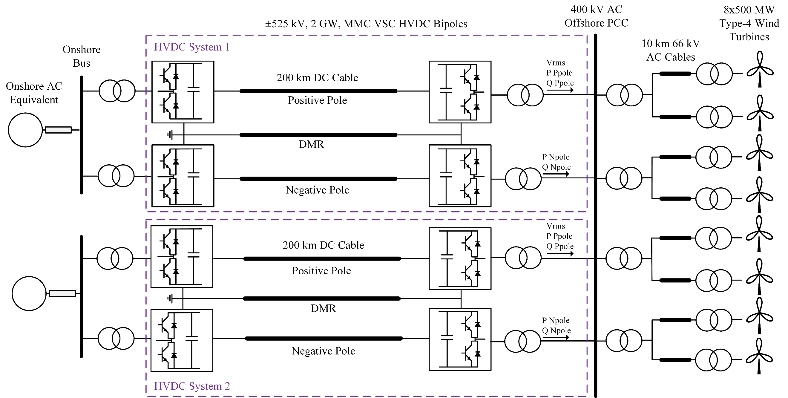
Figure 1 - Test system used to assess the performance of the offshore grid forming
2. Challenges of Offshore Grid Forming Control
Offshore grids have unique dynamic characteristics compared to traditional onshore grids which make the regulation of voltage and frequency challenging, especially when the responsibility of grid forming is distributed amongst tightly coupled parallel bipolar HVDC systems. Previous work has shown that grid forming controls can provide a stabilizing response to fluctuations in grid voltage and frequency [7]. However, interactions between tightly coupled parallel grid forming converters can have negative impacts on system stability. It was found that inertia based SGF control concepts similar to those described in [8]-[13] were inadequate to stabilize the offshore test system.
The following sections summarize the dynamic characteristics of offshore grids and the challenges encountered in implementing an offshore grid forming controller for parallel bipolar VSC HVDC systems.
2.1. Dynamic Characteristics of Offshore Grids
The only rotating mass in the offshore grid are those of the wind plant turbines. Most offshore systems are now using Type-4 (full converter) wind plants where the dynamics of the wind turbines are decoupled from the rest of the offshore system by the inverter. If the wind plant controllers do not implement swing dynamics, there is effectively zero inertia in the offshore system. The swing based SGF control which is used to provide synthetic inertia in traditional onshore grid forming controllers may not be necessary if the offshore grid does not require inertia support.
The active and reactive power outputs from the wind plants are regulated by their respective power plant controllers within a given dispatch period, therefore the offshore HVDC rectifier terminals must be designed to absorb the amount of power determined by the wind plants. That is, the grid forming converters are connected to constant PQ sources as well as in grid forming mode.
Grid forming converters are usually operating in generating mode as they are connected to loads. This gives the converters freedom to change their power output temporarily as required. However, in an offshore wind collector, the converters are operating in power sinking mode with the power level determined by the wind plant controller. This makes the flexibility of the grid forming controllers limited in regulating offshore frequency.
Also, the lack of conventional loads in the offshore grid results in very little damping to transients. These characteristics require a grid forming controller that will cause the offshore converters to respond quickly, and in a coordinated manner to changes in offshore voltage and frequency.
2.2. Challenges of Grid Forming Control in Parallel Bipolar HVDC Systems
There are unique challenges associated with the parallel operation of grid forming bipole HVDC systems. Existing offshore HVDC systems in operation use symmetrical monopoles with a single frequency controller. In a bipole system, each pole requires its own frequency controller. The parallel controllers may fight each other to regulate the PCC frequency, resulting in power circulation between the positive and negative poles of the same bipole.
In a grid forming converter, the AC voltage controller defines the internal voltage magnitude, while the frequency controller defines the internal voltage angle [14]. The assumption is that voltage and angle can be controlled independently. However, it is observed that the AC voltage and angle are highly coupled, making independent control of voltage magnitude and angle difficult. The impact is visible when there are multiple tightly coupled HVDC systems in parallel. It is interesting that this phenomenon is not observed in parallel synchronous generators. The impedance of synchronous generators is highly non-linear, and the steady state impedance is generally larger (~1 pu) than that of VSC HVDC converters (~0.1 pu)[15][16]. The higher impedance results in the internal voltage source being more decoupled between parallel synchronous generators than between parallel grid forming converters. There is also the function of capacitor energy balancing in the submodules of the VSC HVDC system [17]. The energy balancing may create a small error between the internal voltage and angle defined by the grid forming controls and what is produced by the converter. This small error may cause parallel VSC HVDC systems to fight to regulate AC voltage and frequency.
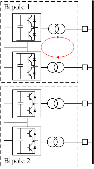
Figure 2 - Power circulation between positive and negative poles of the same bipole
Grid forming converters also require a higher transient current limit than grid following converters to provide the reactive power necessary to support the grid during fault recovery [18]. This problem becomes exacerbated in offshore grids if the HVDC converters must simultaneously sink large amounts of active power during fault recovery. In this scenario the transient current capability of the converter is dominated by active current (id), leaving little margin for reactive current (iq). During a fault, the grid forming converter may reach its transient current limit, at which point the converter is effectively controlled as a current source. Under this condition, the converter is no longer forming the offshore grid since it is not regulating the offshore voltage and frequency. It is critical that the converter return to grid forming as quickly as possible before offshore stability is lost. A higher transient current capability provides additional margin to quickly return to grid forming control. Again, this phenomenon is not observed in synchronous machines because the transient current limit is very high (~3 pu) as it is only limited by the sub-transient impedance and the unit transformer impedance compared to VSC HVDC converters which are limited by the current capability of the IGBTs.
Offshore grid forming control of parallel VSC HVDC converters has been implemented successfully in [19] and [20], where the converters are operating in generating mode to supply an offshore oil and gas grid. One critical difference in offshore grid topology is the addition of a transformer in [20] as well as low voltage AC cables in [19] which electrically decouple the two HVDC links. The parallel control strategy used in [20] is a master-slave topology where one HVDC link acts as the master and controls the AC frequency and voltage while the second link acts as the slave, using a Phase Locked Loop to obtain the angle of the grid voltage. It is possible that other such control schemes can be designed to overcome negative interactions between tightly coupled SGF converters. The following section introduces a control scheme involving a master controller for frequency regulation and pole level controls to define the converter’s internal voltage magnitude and angle.
3. Offshore Grid Forming Control Concept
It was found that applying the SGF based grid forming techniques is extremely difficult for the offshore AC grid due to the aforementioned reasons. Therefore, a novel grid forming concept which is not based on inertia was developed for the offshore grids with tightly coupled HVDC converters.
The offshore VSC HVDC grid forming control concept uses a master offshore frequency regulator as well as individual pole-level controllers. A functional block diagram of the control concept is given in figure 3. The offshore frequency regulator is used to coordinate the distribution of active power for the parallel offshore converters based on the frequency error, while the pole-level controllers define the converter internal voltage and angle. Note that there are no phase locked loops used in the offshore grid forming converters.
3.1. Offshore Frequency Regulator
The coordination of active power between the parallel HVDC systems is done through a frequency droop scheme implemented in a master offshore frequency regulator. The concept of frequency droop to coordinate active power amongst parallel units is well known due to its use in traditional synchronous machines [15]. The offshore frequency regulator measures the PCC frequency and calculates the error between the measured quantity and the reference. For a given frequency error, a new power order is calculated based on the droop setting of the converter and its power absorption.
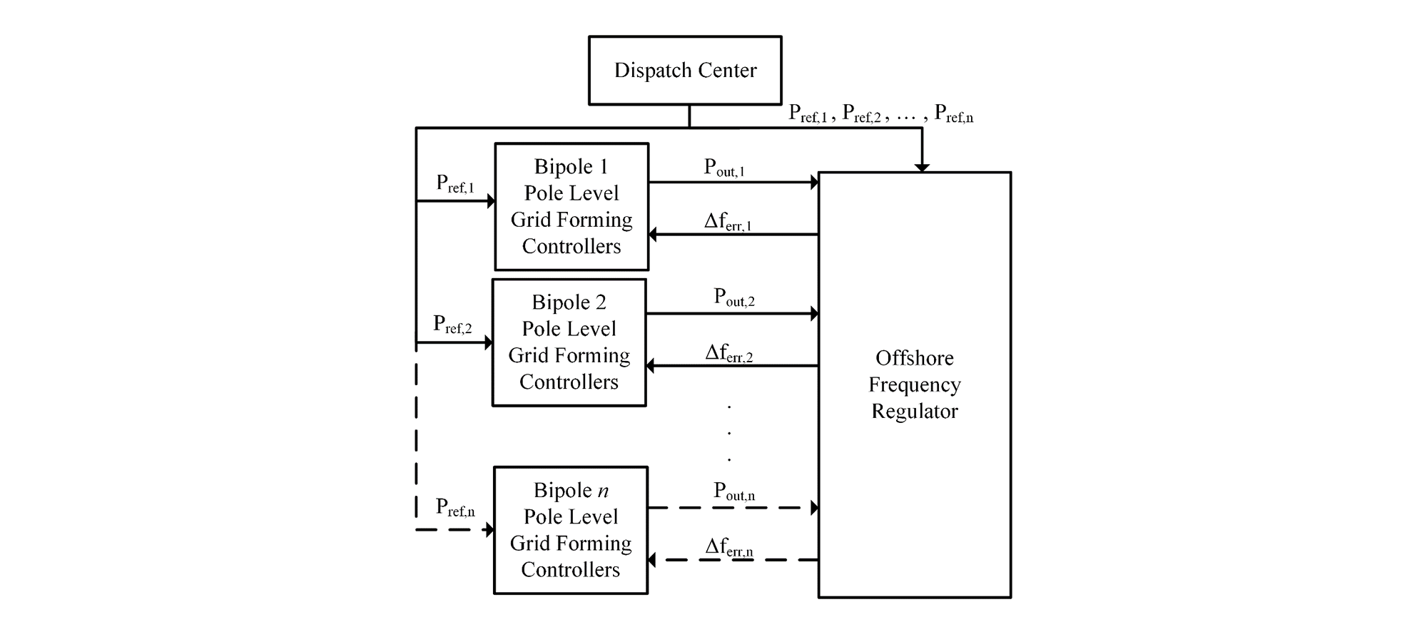
Figure 3 - Functional block diagram of offshore grid forming control concept
If there are n HVDC bipole systems in parallel, the resultant frequency droop (Rtot) is given by:
(1)
Where Rn is the frequency droop of nth HVDC system. The total power mismatch (∆Ptot) in the offshore system is the sum of differences between the power references and the power measurements of each HVDC converter:
(2)
The expected offshore frequency deviation (∆ftot) is then calculated from:
(3)
Finally, the frequency error of each offshore converter () is calculated from:
(4)
The frequency error () is communicated back from the frequency regulator to the individual HVDC controllers which adjust their respective voltage and angle to control the frequency error to zero.
Note that there would be some communication delay between the master offshore frequency regulator and the pole-level controllers. The communication delay could be non-negligible if the two HVDC systems are not physically located on the same offshore platform. This scenario is examined in the EMT simulations of Section 5.
3.2. Pole-Level Controller
The pole-level controller defines the converter’s internal voltage magnitude and angle. Various branches are included to resolve challenges described in Section 2 related to control interactions between parallel offshore converters. Also of note is the lack of swing dynamics in the control structure. Synthetic inertia is excluded from the offshore grid forming controller as the offshore system does not require inertia support to maintain stability. Figure 4 shows the simplified block diagram of the pole-level controller. The following describes the functions of the various control schemes.
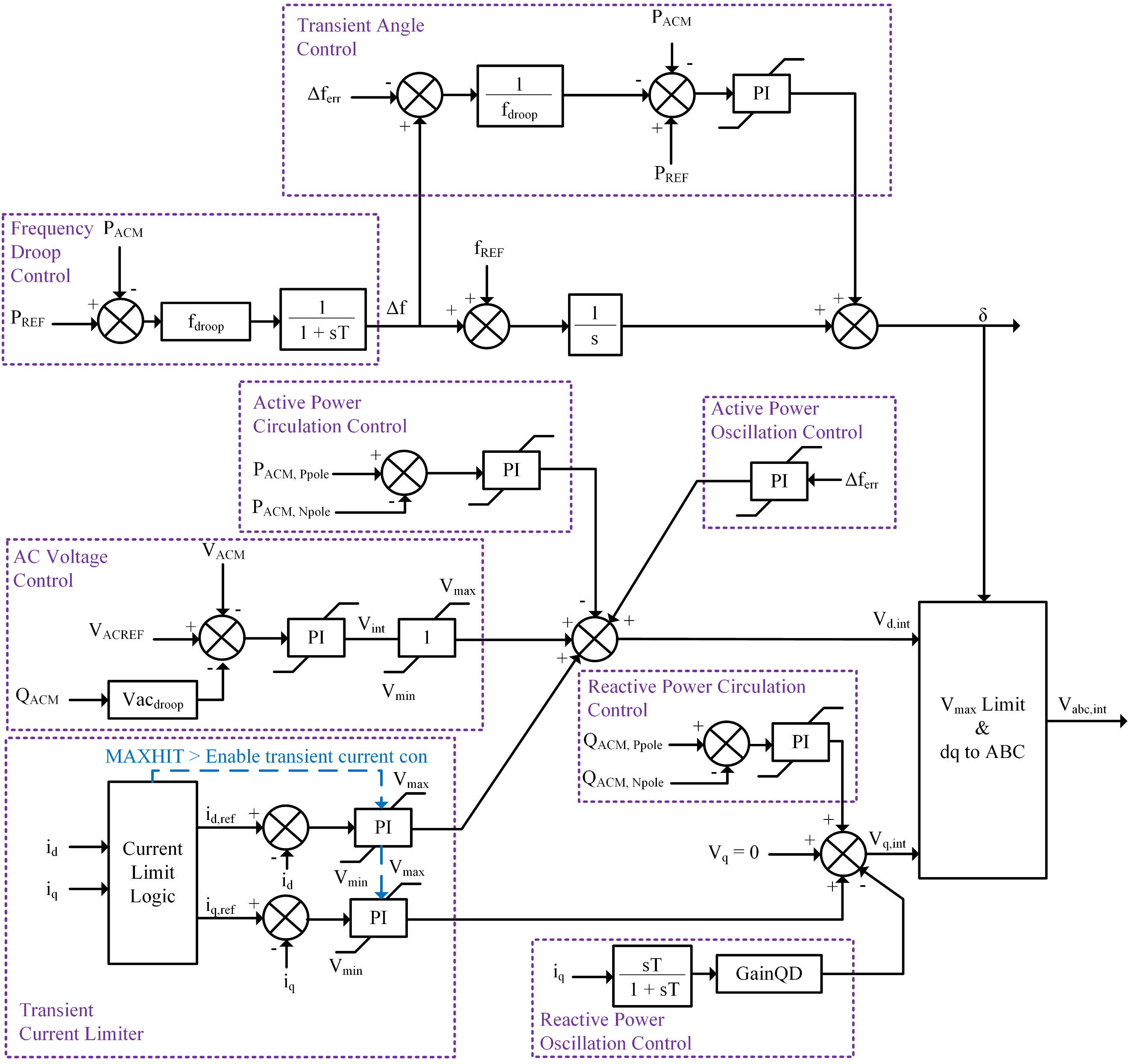
Figure 4 - Control block diagram of the pole-level grid forming controller
Frequency Droop Control: The frequency order of the converter is modulated based on the error between the active power reference and measured power output. This is a relatively slow function, similar to the governor action of generators to regulate the steady state frequency droop.
Transient Angle Control: Quickly modulates the converter internal angle when there is a sudden power change in the offshore grid. The frequency error signal is received from the offshore frequency regulator and divided by the frequency droop to obtain the error in active power as determined by the master controller. This error is compared against the active power reference and output of the converter. The internal angle is quickly adjusted relative to the active power error using a PI controller to maintain the power balance. This is one of the major differences from the SGF swing characteristics. Instead of controlling the frequency, the internal angle is directly controlled to maintain the transient stability of the system.
AC Voltage Control: A reactive power droop concept is used to coordinate the responsibility of AC voltage regulation among the parallel offshore converters.
Active/Reactive Power Circulation Control: Controls the circulation of active and reactive power between positive and negative poles of the same bipole system. Forces the difference in measured P and Q output of the two poles to zero with a PI controller by modulating the direct axis voltage reference relative to active power circulation and quadrature axis reference relative to reactive power circulation. Without these control functions, it is even difficult to maintain stability while energizing the offshore bipole converters.
Active/Reactive Power Oscillation Control: Damps out oscillations in active and reactive power between parallel bipoles. Active power oscillation uses a PI controller to modulate the direct axis voltage reference relative to the frequency error signal sent from the offshore frequency regulator. Reactive power oscillation controller modulates the quadrature axis voltage reference proportional to the quadrature current output. A washout filter is used such that the controller only responds to transients.
Transient Current Limiter: Maintains the converter current within the limits defined by the IGBT short-term current capability. The controller is activated when the converter AC current is close to the limit. Activation of the controller causes the converter to operate as a current source by freezing the normal grid forming controllers. If the current returns to acceptable levels, the controllers are released and regular grid forming control is resumed.
4. Test system
The test system used to analyse the offshore grid forming controller is shown in figure 1. The system considers two ± 525 kV, 2 GW, half-bridge VSC HVDC bipoles. The HVDC systems are connected to a 400 kV AC offshore collector bus. The two HVDC systems are tightly coupled as the offshore collector is modelled as a single bus with negligible impedance. The offshore and onshore converters are connected through 200 km HVDC submarine cables.
The HVDC systems are grounded at the onshore station. Wind generation is modelled as eight arrays of Type-4 wind turbines with an aggregate capacity of 500 MW each for a total nominal offshore power generation of 4 GW. The power plant controllers of the wind farms are configured for P and Q control at the offshore PCC and the wind plants are connected to the offshore collector through 10 km 66 kV AC cables. The parameters of the grid forming controllers for the four offshore converters are identical.
| Offshore Converter | |
Converter Transformer | 273/400 kV, 550 MVA, X=0.1 pu |
DC Side Voltage | 525 kV |
Rated Active Power | 1 GW |
Rated DC Current | 1.9 kA |
Maximum Current | 1.3 pu |
| Offshore Collector | |
Nominal AC Voltage | 400 kV |
Nominal Frequency | 50 Hz |
Type-4 Wind Turbine | |
Nominal AC Voltage | 0.6 kV |
Nominal Frequency | 30 Hz |
Rated Power | 5 MVA |
DC Link Voltage | 1.6 kV |
Units per Array | 112 |
Nominal Cable Voltage | 66 kV |
AC Cable Length | 10 km |
Onshore AC System | |
Nominal Voltage | 380 kV |
Nominal Frequency | 50 Hz |
Short Circuit Level | 12000 MVA |
X/R | 9.9 |
5. Simulation results
EMT simulations were performed on the test system to assess the grid forming controller in an offshore system with two tightly coupled VSC HVDC bipoles. The tests are meant to evaluate the dynamic performance of the controller with respect to small and large-signal stability. The signal locations for the waveforms of voltage and power are provided in figure 1. The frequency order is calculated internally by the pole-level grid forming controller of each offshore HVDC converter.
The initial operating point of the system was configured such that the two HVDC bipoles are transferring nominal power of 2 GW each. All wind plants are generating rated power of 500 MW for a total of 4 GW of offshore wind generation at unity power factor at the offshore PCC bus. The small and large signal stability analysis of the offshore grid shows that the grid forming concept works well even for extreme events such as converter or wind plant outages after a fault.
The results of the following four tests are provided as examples:
- A steady state simulation (no disturbance) is performed with and without the power oscillation control branches active to show how the interactions of the active and reactive power between the two HVDC bipoles are resolved.
- A 100 ms, bolted, 3ph-g fault is applied at the 400 kV offshore PCC with a cross trip of 500 MW of wind generation to show the offshore fault recovery and post-fault power balance.
- Test 2 is repeated with a delay applied to the output of the offshore frequency regulator (master controller) to show the effect of communication delay on grid forming control performance.
- A pole to ground fault is applied on the positive pole of HVDC system 1 at the offshore end of the DC cable with a cross trip of 1 GW of wind generation. HVDC system 1 operates in monopolar post-fault as the event results in the loss of the affected pole, including the offshore and onshore converters. The results show the offshore system recovery with the loss of a pole and the post-fault power balance.
5.1. Interactions between HVDC bipoles
Figure 5 shows waveforms of the two offshore HVDC systems for a steady state simulation (no disturbance) with and without power oscillation control branches activated. The test shows that an instability exists in the offshore system as the active and reactive power of the two HVDC systems begin to move against each other. The power oscillation control in the pole-level grid forming controllers (figure 3) is used to avoid interactions between the two HVDC systems by modulating the converter internal voltage and angle relative to the frequency error provided by the offshore frequency regulator and the converter reactive current output (iq). Activating the controllers resolves the instability resulting from the parallel operation of grid forming bipoles.
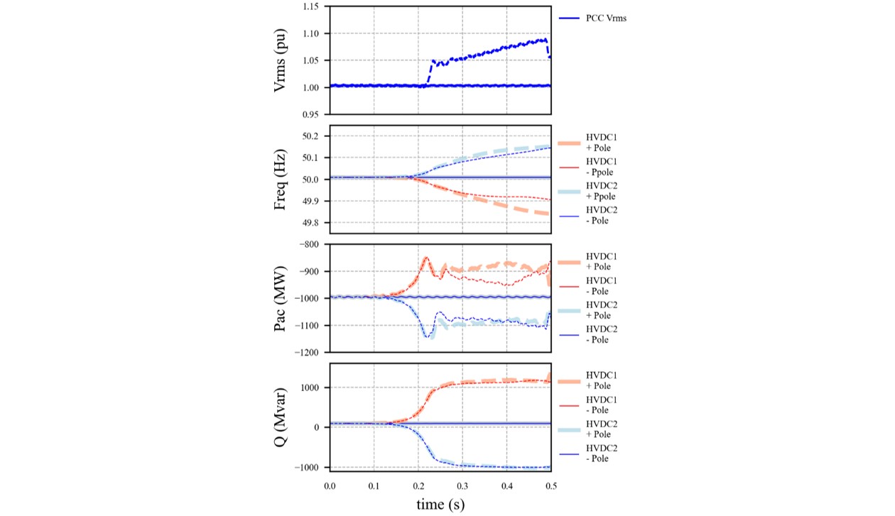
Figure 5 - Steady state simulation (no disturbance) with power oscillations control branches active (solid trace) and inactive (dashed trace)
5.2. Offshore AC Fault
Figure 6 shows the PCC RMS voltage and waveforms for the four offshore HVDC converters for a bolted, 100 ms, 3ph-g fault at the 400 kV PCC, followed by a trip of 500 MW of wind generation. The disturbance results in the PCC voltage and converter power decaying to zero. At fault clearing, the HVDC systems quickly provide the reactive power support necessary to recover the AC voltage and resume the power transfer.
The response of the HVDC systems is nearly identical. A small deviation is observed in reactive power output. The two HVDC bipoles work in a coordinated manner to recover the offshore grid following the disturbance. The power distribution among the HVDC converters is equal, even during transients, and no swings in active power between the converters are observed. Therefore, the performance is much better than what is expected from a SGF based grid forming controller, which produces 2nd order swing dynamics.
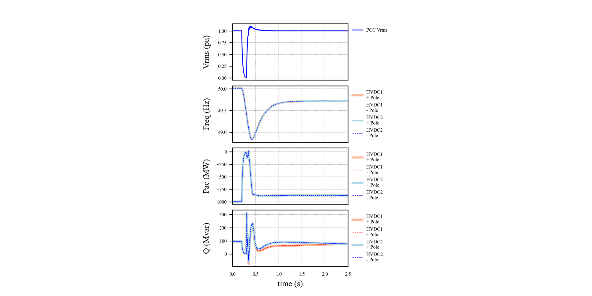
Figure 6 - Offshore HVDC response to a 100 ms 3ph-g fault at the PCC followed by a trip of 500 MW of wind generation
The post-fault power transfer is reduced to approximately 3500 MW and the frequency of the offshore system settles around 49.7 Hz. The offshore frequency regulator calculates the error in the offshore system frequency due to the loss of wind generation. The frequency error is passed to the pole-level grid forming controllers which reduce the amount of power absorption by roughly 125 MW. The offshore power imbalance is distributed equally to the four offshore converters because the frequency droop settings are equal at 5%. Note that the steady-state error in frequency can be controlled within a tighter tolerance by reducing the frequency droop of the HVDC converters. Also, no secondary frequency control structure was considered in this study but could be implemented by adjusting the HVDC reference setpoints to force the offshore frequency back to 50 Hz.
The offshore steady state frequency can be confirmed analytically using equation (5). With a nominal offshore frequency of 50 Hz, a calculated frequency deviation of 0.298 Hz agrees with the results obtained through simulation. Note that the rating of each HVDC bipole was assumed to be 2100 MW.
(5)
5.3. Offshore AC Fault with Communication Delay
A bolted 100 ms, 3ph-g fault at the offshore PCC with a trip of 500 MW of wind generation was repeated with a communication delay between the offshore frequency regulator and the pole-level controls. For this test, a communication delay of 1 ms was considered between the offshore frequency regulator and the pole-level controls of HVDC system 1, and a 20 ms delay to the pole-level controls of HVDC system 2. Figure 7 shows the offshore PCC voltage and frequency order of the two positive pole converters for both HVDC systems with and without the communication delays. It is shown that the signal delay has negligible effect on the system response to the fault. This test shows that the proposed grid forming control concept can be implemented if the offshore converters are physically separated by a distance.
This scenario considers the condition where the offshore converters of the two bipoles are located at a different offshore platform. In reality, the offshore frequency regulator would be located at one offshore platform with some delay in the communication signal to the second platform.
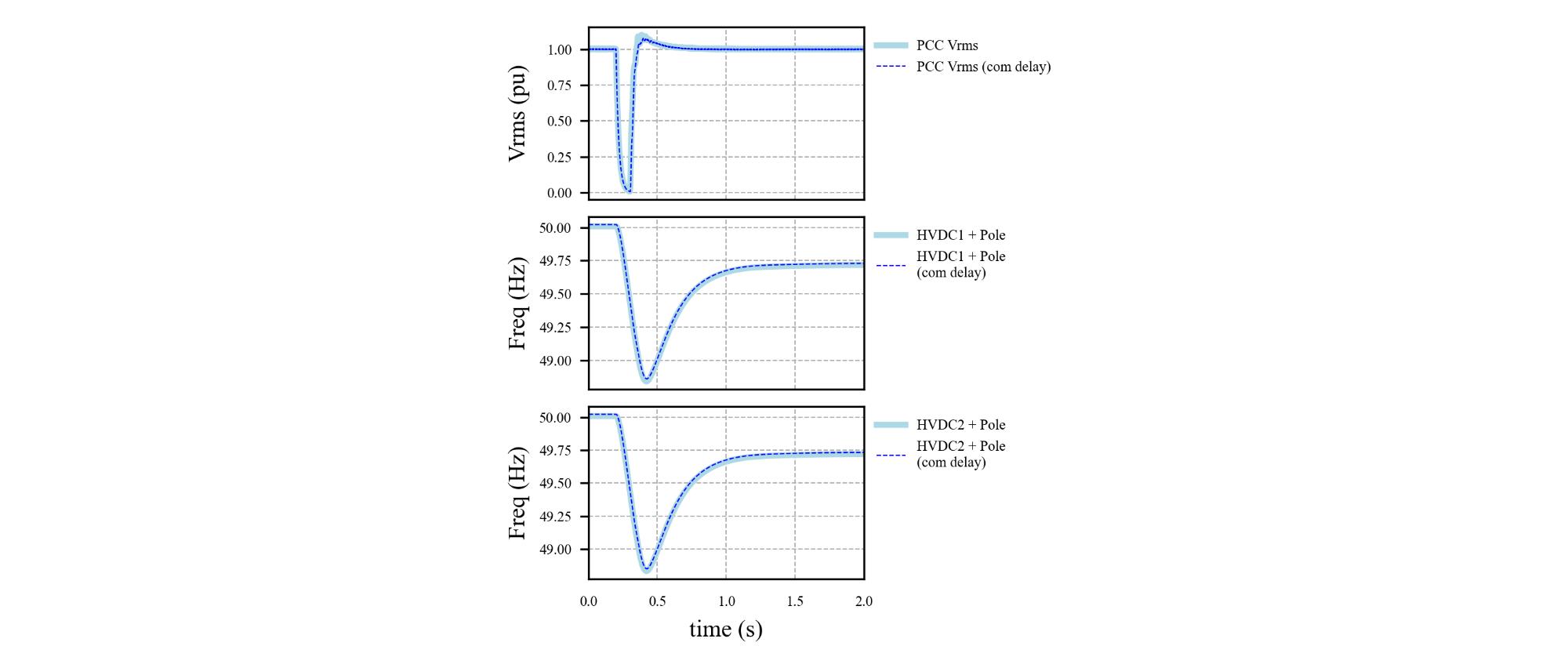
Figure 7 - Offshore PCC fault with and without communication delay between the master controller and pole-level controllers
5.4. DC Fault
Figure 8 shows the PCC voltage and offshore HVDC converter frequency order and power absorption for a pole to ground fault on the positive pole of HVDC system 1 at the offshore end of the DC cable. The fault causes the offshore and onshore converters of HVDC system 1 positive pole to block, followed by AC breaker operation to isolate the faulty pole. During the fault, the faulty converter absorbs a significant amount of power while the healthy converters reduce their power absorption. Therefore, no significant excess power is absorbed by the wind plants. HVDC system 1 operates as a monopole with Dedicated Metallic Return (DMR) after the fault is cleared. With the trip of the positive pole, the offshore wind hub loses 1 GW of transfer capability. To balance power generation with the lower transfer capability, 1 GW of wind generation is cross tripped with a delay of 100 ms from fault inception.
The healthy offshore HVDC converters increase their reactive power injection to the PCC to support the voltage during the fault. The reactive power injected by the three healthy converters flows to the short circuit through the freewheeling diodes of the blocked converter, resulting in very high reactive power absorption (~ 3 GVAR) by the offshore converter of the faulted pole. The voltage quickly recovers after the faulted pole is isolated and the post-fault power transfer returns to 1 GW on the three healthy poles. Note that the post-fault power transfer is the same as pre-fault due to the cross trip of 1 GW of wind generation, that is, the amount of generation cross trip is equal to the initial power transfer on the faulty pole.
The performance of the transient angle control loop of the pole-level controller can be clearly observed in the negative pole of HVDC system 1. Initially, the converter begins to increase its active power absorption during the fault, causing the frequency order of the pole to increase. This is because the healthy pole can initially feed a large current to the DC fault (offshore neutral point is ungrounded). The control loop quickly modulates the converter internal voltage angle based on the frequency error signal provided by the offshore frequency regulator. The change in internal angle causes a decrease in the active power absorption of the converter and lowers the frequency order. The frequency order of the three healthy offshore HVDC converters returns to the initial level.
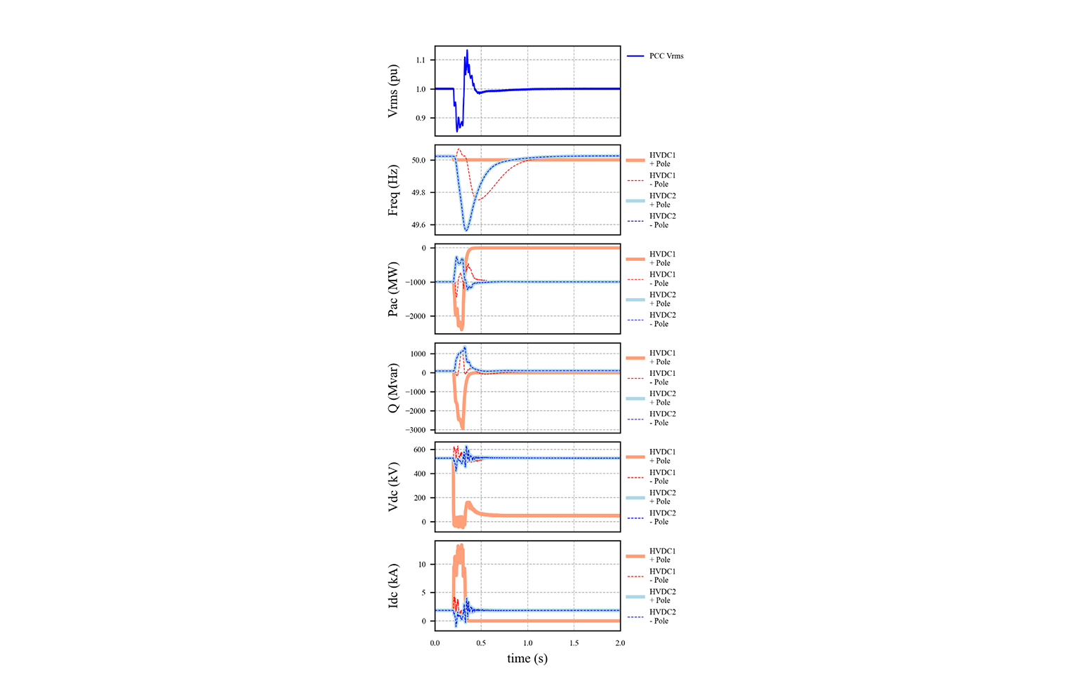
Figure 8 - Offshore HVDC response to a pole to ground fault on HVDC system 1 positive pole and trip of 1 GW of wind generation
6. Conclusion
This paper presents the need for further investigation into the stability of SGF converters when considering the unique dynamics characteristics of offshore wind collector systems. Characteristics of offshore grids are discussed, including the lack of inertia, constant PQ power generation by wind plants, and lack of conventional loads which limit the flexibility of VSC HVDC grid forming controllers to regulate offshore frequency. The challenges encountered when operating two tightly coupled VSC HVDC bipoles in parallel are also discussed, including circulation of power between positive and negative poles of the same bipole, interactions between the two separate bipoles, and considerations regarding converter transient current capability.
A grid forming control concept is introduced which implements a master controller for offshore frequency regulation and pole-level controllers for defining the converter internal voltage and angle. Due to the unique characteristics of offshore grids, traditional SGF based grid forming controls proved inadequate in stabilizing the offshore grid. Special control structures are used to limit power circulation and decouple the internal voltage magnitude and angle controllers.
Finally, EMT simulation results are provided to show the resolution of the interactions in the offshore grid, assess the performance of the offshore frequency regulator, show the fault ride through performance of the grid forming controls, and assess the impact of communication delay between the master controller and pole level controllers. The tests show that the grid forming control concept works well as the offshore system is stable in terms of both small-signal and large-signal stability.
References
- K. Meah and S. Ula, "Comparative Evaluation of HVDC and HVAC Transmission Systems," 2007 IEEE Power Engineering Society General Meeting, 2007, pp. 1-5, doi: 10.1109/PES.2007.385993.
- N. Flourentzou, V. G. Agelidis and G. D. Demetriades, "VSC-Based HVDC Power Transmission Systems: An Overview," in IEEE Transactions on Power Electronics, vol. 24, no. 3, pp. 592-602, March 2009, doi: 10.1109/TPEL.2008.2008441.
- European Network of Transmission System Operators for Electricity, “Offshore Transmission Technology”, November 24, 2011. Available: https://eepublicdownloads.entsoe.eu/clean-documents/pre2015/publications/entsoe/SDC/European_offshore_grid_-_Offshore_Technology_-_FINALversion.pdf
- J. Gleadow, G. Love, H. Saad, T. Rauhaia, C. Barker, A. Canelhas, M. Barnes, G. Denis, S. Bartlett, E. Prieto Arujo, X. Chen, S.M. Iftekharul, V. Pathirana, K. Schonleber, J. Rittinger, K. Koreman, J.N. Paquin, J. Sakamuri, “TF-77 – AC fault response options for VSC HVDC converters”, CIGRE Science & Engineering, vol. 15, pp. 105-110, October 2019.
- F. Milano, F. Dörfler, G. Hug, D. J. Hill and G. Verbič, "Foundations and Challenges of Low-Inertia Systems (Invited Paper)," 2018 Power Systems Computation Conference (PSCC), 2018, pp. 1-25, doi: 10.23919/PSCC.2018.8450880.
- North Sea Wind Power Hub Programme, “Towards the first hub-and-spoke project”, concept paper 2021, Available: https://northseawindpowerhub.eu/sites/northseawindpowerhub.eu/files/media/document/NSWPH_Concept%20Paper_05_2021_v2.pdf
- OSMOSE, “Final Report”, Available: osmose-h2020.eu
- A. J. Roscoe, M. Yu, A. Dyśko, C. Booth, R. Ierna, and J. Zhu, “A VSM (Virtual Synchronous Machine) Convertor Control Model Suitable for RMS Studies for Resolving System Operator / Owner Challenges,” p. 8
- Q.C. Zhong and G. Weiss, “Synchronverters: Inverters That Mimic Synchronous Generators,” IEEE Trans. Ind. Electron., vol. 58, no. 4, pp. 1259–1267, Apr. 2011, doi: 10.1109/TIE.2010.2048839.
- J. Zhu, C. D. Booth, G. P. Adam, A. J. Roscoe, and C. G. Bright, “Inertia Emulation Control Strategy for VSC-HVDC Transmission Systems,” IEEE Trans. Power Syst., vol. 28, no. 2, pp. 1277–1287, May 2013, doi: 10.1109/TPWRS.2012.2213101.
- J. Rocabert, A. Luna, F. Blaabjerg and P. Rodríguez, "Control of Power Converters in AC Microgrids," in IEEE Transactions on Power Electronics, vol. 27, no. 11, pp. 4734-4749, Nov. 2012, doi: 10.1109/TPEL.2012.2199334.
- Y. Chen, R. Hesse, D. Turschner, and H.-P. Beck, “Comparison of methods for implementing virtual synchronous machine on inverters,” Renew. Energy Power Qual. J., pp. 734–739, Apr. 2012, doi: 10.24084/repqj10.453
- H. Bevrani, T. Ise, and Y. Miura, “Virtual synchronous generators: A survey and new perspectives,” Int. J. Electr. Power Energy Syst., vol. 54, pp. 244–254, Jan. 2014, doi: 10.1016/j.ijepes.2013.07.009
- M. Guan, W. Pan, J. Zhang, Q. Hao, J. Cheng, and X. Zheng, “Synchronous Generator Emulation Control Strategy for Voltage Source Converter (VSC) Stations,” IEEE Trans. Power Syst., vol. 30, no. 6, pp. 3093–3101, Nov. 2015, doi: 10.1109/TPWRS.2014.2384498X8 J.
- P. Kundur, “Power System Stability and Control”, McGraw Hill, 1994
- M. Amin and M. Molinas, "Understanding the Origin of Oscillatory Phenomena Observed Between Wind Farms and HVdc Systems," in IEEE Journal of Emerging and Selected Topics in Power Electronics, vol. 5, no. 1, pp. 378-392, March 2017, doi: 10.1109/JESTPE.2016.2620378.
- M. Lehmann, C. Hahn and M. Luther, "A novel approach for energy balanced operation of submodules in multilevel VSC HVDC systems," 2015 50th International Universities Power Engineering Conference (UPEC), 2015, pp. 1-6, doi: 10.1109/UPEC.2015.7339898.
- M. Annakkage, C. Karawita, H. Suriyaarachchi, U.D. Annakkage, “Voltage and frequency support of modular multilevel converters connected to weak grids,” CIGRE Science & Engineering, vol. 15, pp. 94-104, October 2019.
- S. Dennetiere, P. Rault, H. Saad, Y. Fillion, K. Sharifabadi, J.H. Johansson, N. Krajisnik, “Technical solutions to predict and mitigate inadvertent interaction of two parallel connected VSC-HVDC schemes feeding an islanded offshore Oil and Gas grid”, B4-138 presented at the CIGRE Paris session 2020.
- A. Sinkar, A. Gole, V. Pathirana, U. Gnanarathna, “Design Considerations for Parallel HVDC Links Feeding Offshore Platforms”, B4-111 presented at the CIGRE Paris session 2018.