Distribution Feeder and Critical Load Blackstart and Restoration using Inverter Based Resources
Authors
D. RAMASUBRAMANIAN, W. BAKER, V. SINGHVI, S. UPPALAPATI, E. FARANTATOS
Electric Power Research Institute, Knoxville, TN, USA

Summary
Around the world, restoration is treated as a critical aspect of power system operations and planning. The timeline of a restoration process starts when a blackout (or a widespread outage) is recognized and ends when the power system reaches a normal operating state. An increase in percentage of inverter-based resources (IBRs) displacing conventional rotational machines in the bulk power system has prompted planners to reassess restoration plans and strategies. In this paper, use of an IBR to blackstart and energize a transmission path will be discussed. The impact of the IBR control architecture along with the characteristics of the load will be showcased and solutions to bring about successful restoration will be touched upon.
Keywords
Blackstart - grid forming - restoration - single phase induction motor1. Introduction
Power system restoration is the process of returning genera- tors and transmission system elements to service and restoring load following an outage on the electric system [1]. Around the world, restoration is treated as a critical aspect of power system operations and planning. The timeline of a restoration process starts when a blackout (or a widespread outage) is recognized and ends when the power system reaches a normal operating state [2]. The focus during restoration is on reestablishing stable operation of the power system with enough skeleton so that resources and supply to end-use customers can be restored as expeditiously as possible to minimize interruptions to social life and the economy [3].
The granularity of the restoration process and steps varies among system operators (SOs). In general, any restoration process can be summarized as shown below:
Step1: System Status Assessment
An immediate assessment of system conditions, includ- ing the available transmission and generation resources, is an essential first step. The Supervisory Control and Data Acquisition (SCADA) and Inter-Control Center Communication Protocol (ICCP) data can help with the assessment, which is dependent upon the availability of Remote Terminal Units (RTUs), Energy Management System (EMS) equipment and the associated infrastructure. Communicating with member Transmission Operators (TOPs) and neighboring SOs is also essential, which is dependent upon the availability of communication equipment and dedicated personnel. While some data may be missing due to facilities being out of service and/or damage to equipment, it is essential to review all the available data to come up with a reasonable picture of resources available to initiate restoration.
Step 2: Determine and Implement Restoration Strategy
Based on Step 1, the restoration strategy needs to be revisited and revised by the SO to take into consideration the existing system conditions and availability of key transmission and generation facilities. This can help in coming up with a high-level restoration sequence. This revised strategy must be then communicated by the SO to the affected entities such as the TOPs and neighboring SOs.
Step 3: Implement Restoration Procedures
TOPs can start restoring the transmission, generation and load facilities, while maintaining satisfactory voltage and frequency performance. This step also includes synchronizing islands after they have been stabilized. For this implementation step, the TOP can use the guidelines documented in its SO’s restoration plan. During the early stage of restoration, voltage and frequency performance is an extremely critical factor. Accordingly, all SOs provide guidelines on voltage and frequency performance monitoring and adherence. This involves issues such as Ferranti voltage rise [4]–[6], switching shunt devices, balancing generation and load, adding load following a transmission line energization, etc.
Step 4: Interconnection with Other TOPs
When appropriate, using tie lines to connect with neighboring TOPs can expedite the restoration process at the interconnection level. Providing assistance to a neighboring TOP is encouraged as long as it does not cause an adverse impact to the restoration process. It is worth noting that according to some SO guidelines [7], [8], after a TOP has been able to stabilize its subsystem or island, supplying restoration power to a neighboring system is of higher priority than supplying additional load in its own system.
When implementing step-by-step facility energization procedures in real-time following a blackout, the power system behavior is quite different compared to its behavior during normal operation. The system being restored is weak and the first black start resource essentially ‘lights up’ a dark network which can be assumed to have a short circuit strength of 0.0, which can produce large and unacceptable deviations in voltage and frequency, thus causing potential regression. Therefore, the standard operating practices for normal power system are generally not appropriate. With each step in the energization process that causes a change in IBR terminal voltage, the controls of the inverter would try to change the value of their injected current to satisfy their objective, which could either be voltage and frequency control or active power/reactive power control. The root cause of instability at such a time is fast IBR controllers trying to lock onto a system that is itself moving fast in order to maintain rigid current control. From basic control theory, we know that use of high bandwidth fast controllers to control a process in a system that moves fast drastically reduces the stability margin of the controller. Thus, it can follow that conventional phase locked loop (PLL) based IBR controls may be unable to operate in a 100% inverter-based island.
It has been independently shown in both [9] and [10] that to achieve inverter based generation levels greater than 65% of the load served, the presence of PLL based IBR controls may be detrimental to system stability. Instead, controllers that would allow the grid to view an inverter as a voltage source rather than a current source would be required [11], [12]. These controllers essentially allow the magnitude and phase of the injected current to be largely uncontrolled if it is within the current limits of the inverter power electronic components. This allows for fast injection of current into the network.
There are articles available in research literature that have touched upon system restoration with inverter based resources. Among them are references [13]–[17]. However, [13] considers the black start unit to be a synchronous generator with isochronous governor. Additionally it doesn’t consider the impact of induction motor loads. While an optimization scheme has been formulated to take into consideration the dynamic characteristics of load, the operation of such a scheme is dependent only on synchronous machine behavior. The simulation cases presented also do not consider transformer inrush and line charging. The approach in our paper makes use of an assumption that the initial restoration scheme does need to consider transformer energization and line charging while utilizing fast inverter controls.
References [14] and [15] develop an optimization approach to develop the switching sequences during an energization process. However, [14] doesn’t explicitly consider inverter based resources, while both [14] and [15] again do not consider the impacts of transformer energization and line charging on the restoration. Reference [15] also takes into consideration weather based forecast to estimate the available energy from PV units depending on the level of sunshine. In the method outlined in our approach here in this paper, this estimate of available energy is rolled into the algorithm to determine the switching sequences of generators and lines.
Further, many a time, from a practical perspective, it is not possible to include detailed information of inverter controls into a system planner’s strategy for optimizing a restoration sequence as the system planner may not have information related to the black box model of the inverter. Thus, a sequential process would be necessary as detailed in our approach. Additionally, different types of controller interactions that can arise during restoration have to be considered as highlighted in our paper.
A major contribution of the paper is to highlight system restoration while continuing to use a conventional inverter-based resource control structure wherein a PLL is used to both form and follow the grid at the same time. This work builds upon our previous works where such control schemes have been used to continue to operate a 100% inverter-based grid without the use of droop based or virtual synchronous machine-based control. To our knowledge, none of the state of the art approaches the inverter-based resource restoration problem from this perspective. It is always assumed that PLL based resources would be unable to provide suitable blackstart services from a stability scenario. However, with modifications of the PLL to make it more robust, and with appropriate parameterization of the various control loops, there are aspects that may be leveraged. Here in this paper, two additional stabilization loops have been added, (1) a power system stabilizer based control loop in the inverter reactive control loop and (2) and rate feedback based stabilization loop in the phase locked loop. Both these concepts have been derived from existing stabilization techniques that have been historically applied to synchronous machines in weak grids.
Finally, [16] assumes that the inverter within the microgrid behaves as a virtual synchronous machine and thus exhibits properties inherent to synchronous machines, while [17] assumes a droop based control. Also, [16] concludes that motor starting is not an issue due to the fact of an inherent assumption that two or more inverters operate in the virtual synchronous machine mode. However, this may not always be possible in a real world. So in the event that these resources are not available, and only few IBRs are available, motor starting, especially between different types of motors, there can be issues to the system as shown in our paper.
An overview of the tools and process that can allow for efficient restoration studies has been documented previously in [18]. While the reference does look at few high level case studies to support the narrative for various tools and methods, this paper extends the case studies to more detailed topologies and layout, especially from the structure of the load characteristics. Further, the paper also looks at restoration in the presence of more than one inverter resource.
The rest of the paper is structured as follows: Section II provides a brief overview of the state of the art in system restoration while Section III provides a description of the controller used for the IBR blackstart unit. The application of this control setup to numerous scenarios during blackstart and system restoration is discussed in Section IV while Section V provides concluding remarks.
2. State of the art in the process of restoration
To ensure satisfactory voltage and frequency performance, it is essential for a TOP to perform studies of its step-by-step facility energization procedures. Such studies are required as part of compliance to restoration standards/codes [1], [2]. Both steady state and transient stability studies are performed to verify these restoration plans.
The aim of the of steady state analysis at each step of the restoration process is:
- To ensure that all thermal and voltage limits are within the study criteria . The study criteria can vary based on study system, voltage level, etc
- To ensure blackstart units has enough capability to absorb reactive power, especially during early restoration, produced by transmission line charging.
- To ensure load and generation balance at each restoration step.
The aim while conducting a transient stability analysis, using conventional positive sequence stability simulation software, is:
- To verify the dynamic performance of each unit in the power plant by monitoring the real power output, reactive power output, voltage magnitude, and frequency.
- To verified that for each step of the restoration process, no under frequency load shedding (UFLS) relays or generation relays are activated.
- To determine the best frequency control operation mode (either droop or isochronous mode) that is to be adopted by the black start resources.
In addition to steady state and dynamic analysis, every restoration plan should address the performance of protective relaying and control schemes during restoration conditions to ensure there is no undesired tripping of load, generator, transformer or transmission lines.
In a traditional power system restoration plan with synchronous/rotating machines based black start resources, an electromagnetic transient (EMT) study is not usually carried out as the dynamic behavior of rotating machines can be precisely defined within the first few hundred milliseconds of the energization event. While some utilities have begun exploring the use of EMT simulation software in their black start studies to observe the impact of transformer and line energization, the practice is not widespread, especially with rotating machine based black start units. However with an inverter based resource (IBR) being used as the designated black start resource, although the aim and objective of the black start study still remain the same as with rotating machines, carrying out an EMT study is critical to ensure that the control system of the IBR is able to successfully energize the lines, transformers, and loads while maintaining voltage and frequency. With IBRs, due to the nature of their different control loops, some of which have a response time that is within the transient time frame of line dynamics, it becomes important to identify whether the IBR will be stable and will be able to provide the required energization currents. Further, if saturation of the transformer core occurs, then its impact on the controller of the IBR and power quality during restoration is also to be ascertained. Additionally, EMT studies can also provide insight into the interaction between induction motor starting schemes and IBR control schemes, not to mentioned visibility into fault ride through behavior during restoration.
3. Structure of controller used in IBR black start unit
An inference may be made from state of art weak grid research literature that an operation of the power system with 100% inverters would not be possible if a PLL exists, but it has previously been shown in [19], [20] that with careful design and tuning of the PLL based IBR controls, the viability of operating a 100% inverter based system with only PLL based control architectures is indeed possible. This operation is made possible by,
- introducing robust design in the structure of the phase locked loop,
- appropriate tuning of the controller gains, and
- introduction of an outer loop angle, frequency, and voltage control.
Here in this study, this previously developed IBR control for a zero inertia system is used to demonstrate the black start capability of an IBR. The diagram of the control topology used is shown in Fig. 1.
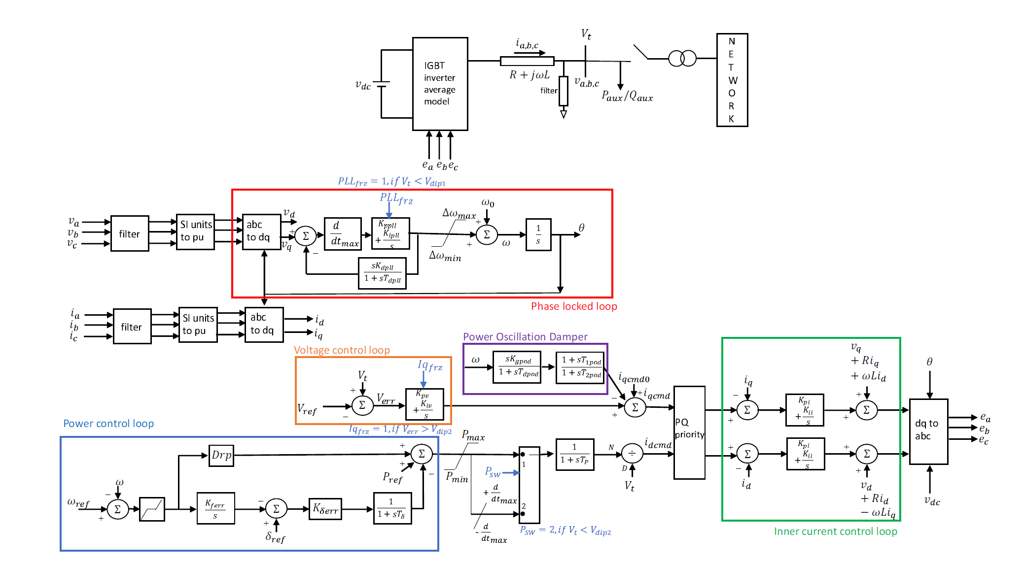
Figure 1 - Block diagram of inverter based resource control used in this study
There are five main control loops in this structure are:
- Phase locked loop: A conventional synchronous reference frame PLL has been modified with addition of
- an input rate of change limiter that slows down the PLL and makes it reject fast changes in input voltage,
- a rate feedback element that improves the synchronization capability of the PLL by adapting to fast changes in angle output, and
- logic to freeze the integral state based on the magnitude of input voltage to allow for more robust fault ride through behavior.
These modifications enable a more robust PLL behavior under low short circuit conditions.
- Power control loop: Based upon a value of frequency obtained from the phase locked loop, the active power command (and subsequently active current command) of the IBR is modified on a frequency droop law (based upon the recommendations in FERC Order No. 842 [21]) and an additional angle droop law previously proposed by EPRI [19], [22]
- Voltage control loop: Using the measured terminal voltage magnitude, the reactive current command is modified to meet a specified fixed reference terminal voltage (based upon the recommendations in FERC Order No. 827 [23]). Here, a lack of reactive power droop is not critical as droop on voltage primarily comes into effect when two or more resources try to control voltage at the same point in the system (for example parallel connection at a bus). If needed, a reactive power droop could easily be added to the controller and this could in-effect modify the value of Vref . However, during restoration, the use of reactive power droop will have to be carefully monitored as when induction motors are started, a large amount of reactive power is drawn. This could then result in the lowering of the effective value of Vref (if reactive power droop is used). A lowering of the value of Vref could subsequently cause a motor to stall due to lower voltage.
- Power oscillation damper: A varying amount of phase lag is applied with each step in the restoration process. This can cause the voltage control loop and the phase locked loop to become unstable. To mitigate oscillatory instability to the greatest extent, a power oscillation damper based control loop is present in the voltage control loop.
- Inner current control loop: The final voltage developed by the inverter on its ac side is governed by the inner current control loop that tries to ensure that the current injected by the IBR into the network is approximately the same as the reference current.
The expectation is that the IBR would be able to serve its own auxiliary load (which could include balance of plant cooling system load) before being connected to the transmission network. Here is it is assumed that the energy source behind the IBR is either a battery energy storage system (BESS) or a photovoltaic (PV) plant with sunshine available. Thus, here, an uninterruptible power supply is not assumed to be present as the dc side power from the BESS or PV plant can be used to supply the power to the circuit elements of the IBR. Although Type 4 wind can also be used, the model did not represent dynamics of the turbine and hence the source is assumed to be either a stationary source like BESS or PV. If Type - 4 or Type - 3 wind units are used during restoration, representation of the dynamics of the turbine is important as there can be mechanical stress on the blades and shaft of the turbine that can limit the capability of the wind unit to provide required services. Once connected to the network, the controls of the IBR would then be able to handle the transient involved with energization and load pick up. The following section will discuss EMT simulation studies that showcase the application of the control structure for use in system restoration.
4. Simulation and results
The initial restoration path studied is shown in Fig. 2. At the time the system goes black, all breakers in the network are open. The MVA rating of the IBR and its local 0.575/21.6kV transformer is considered to be 25 MVA. The 21.6kV/500kV transmission transformer is however rated at 250 MVA while the 500kV/230kV transformer is rated at 500 MVA. All transformers have a leakage reactance of 8% on their self MVA base and draw a magnetization current of 0.3% with an inrush decay time constant of 1.0s.
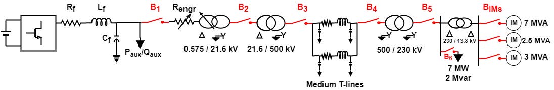
Figure 2 - Restoration path to be energized by a single inverter based resource
A. Start up of IBR
According to the developed restoration plan, the IBR should start with self-energizing its local auxiliary load. For this 25 MVA IBR, the auxiliary load is assumed to be 1.8 MW and 0.06 Mvar. At t=0.0s the IBR is started with a fixed constant value of idcmd and iqcmd. Initially for the first 1.5s the power control loop and the voltage control loop (including the power oscillation damper) are disabled to allow the phase locked loop and the inner current control loop to stabilize. Since the magnitude of auxiliary load of the IBR is known (as it is assumed to be within the plant), the initial current command values can be ascertained beforehand such that a voltage close to 1pu (or any other voltage magnitude) is obtained at the IBR side of breaker B1. The auxiliary load in this scenario was represented by a constant current static model for active power and a constant impedance static model for reactive power. The reference point of control for the IBR is on the IBR side of its auxiliary load. To achieve this operation mode, the value of idcmd and iqcmd are kept constant. In the reactive control path this manifests as Kpv = Kiv = Kgpod = 0.0 while in the active control path it manifests as constant Pref at a voltage of constant 1.0pu with Kδerr = Drp = 0.0.
The rms voltage and current magnitude along with the real and reactive power output during start-up of the IBR from t=0.0s to t=1.0s is shown in Fig. 3.
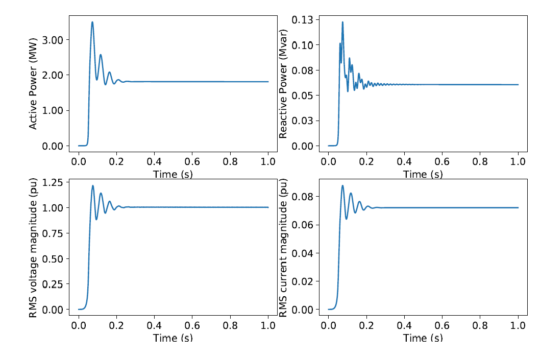
Figure 3 - Active power, reactive power, rms voltage magnitude, and rms current magnitude of 25 MVA IBR in the first second of start up
The simulation here is run with a solution time step of 50µs. From the figure, the phase locked loop and the inner current controller of the IBR have a stable response and the IBR can serve the auxiliary load while meeting an acceptable voltage magnitude. The frequency output from the PLL is shown to left in Fig. 4.
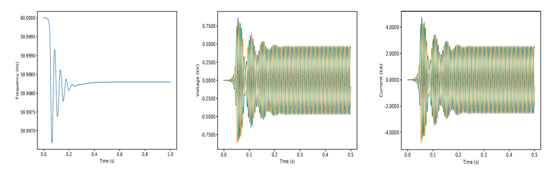
Figure 4 - Frequency from phase locked loop along with three phase voltage and current waveforms at the inverter terminals
Since the PLL is a variant of a synchronous reference frame PLL, it has a fixed starting frequency denoted as ω0 as shown in Fig. 1. This frequency is usually set to be the synchronous frequency of the system. However here, as there is no grid for the PLL to align its frequency against, one can ask a question of whether this PLL will be stable and what would it follow?
Since the entire control structure of the IBR is a closed loop control system, with proper tuning of the control gains, one can get the PLL to both follow itself and form the grid at the same time. Evidence of this behavior is further obtained from the central and right plots shown in Fig. 4 which show the instantaneous values of voltage and current at the IBR terminals is shown for the first half a second. The result here shows that even with a current source grid following control structure, if the proper current commands are provided, and if the controllers are adequately tuned, one can obtain a stable response.
Here, the inner current control loops are tuned using the principle of internal model control to obtain a value of proportional-integral gains (Kpi and Kii) as 0.25 and 70.0 respectively. Initially, when no load has been picked up and only lines and transformers are energized, the PLL gains (Kppll and Kipll) are kept as 2.0 and 0.01 respectively for the proportional-integral gains. However once the load is picked up, the gains are increased. The droop gain in the active power control loop is kept as 0.0 until the load is picked up at which point the gain is changed to 10.0, while the voltage control proportional-integral gains are kept as 0.01 and 2.0 respectively. To observe the impact of starting up the IBR with voltage and power control enabled right at t = 0.0s, Fig. 5 compares the rms voltage magnitude and the PLL electrical frequency of the IBRs. When starting at t = 0.0s, initially the voltage at the terminal is 0.0. As a result, there can be a tendency for the voltage control integrator to saturate as the voltage builds up to 1.0 and due to this saturation, continued operation of the controls can result in saturation of the modulation index of the converters.
B. Transformer energization
At t = 6.0s the breaker B1 is closed to energize the IBR’s step-up transformer. To prevent excessive inrush current, the transformer is energized using a soft energization mechanism by using a series variable resistance (Rengr). Temporarily inserting a large value of resistance (20pu on the MVA base of the IBR) in series results in a voltage drop across the resistor thereby reducing the voltage observed at the low voltage terminal of the transformer. Due to the low voltage, the inrush current drawn is greatly reduced. Following energization, the value of the resistance is reduced to increase the voltage on the low and high voltage side. The instantaneous current observed at the IBR terminals and at the low voltage side of the 0.575kV/21.6 transformer is shown in Fig. 6.
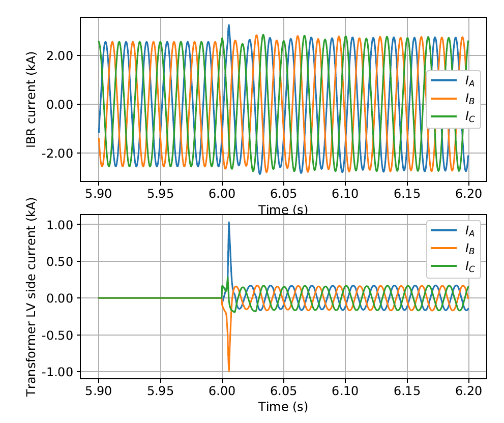
Figure 6 - Instantaneous current observed at IBR terminals and low voltage terminals of the 0.575/21.6 kV transformer upon its energization
Due to the soft energization mechanism, only a marginal inrush current is observed at the IBR terminals while a much larger inrush current is observed at the transformer. The subsequent reduction of the value of the resistor (Rengr) to an intermediate value leads to the increase in voltage at the open circuit high voltage side of the transformer. Although here the resistance is represented by a resistance element, in practice it could also be a power electronic device that presents an apparent resistance in the network.
C. Energization of entire path
After conducting the subsequent steps in the restoration process until energization of the load bus, the rms voltage at the IBR terminal, at the 21.6 kV bus and the 500 kV bus of the IBR plant is shown in Fig. 7 along with the frequency from the PLL within the IBR controls.
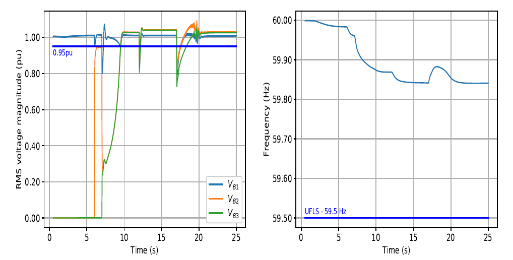
Figure 7 - RMS voltage magnitudes and PLL frequency for the entire duration of system restoration up to the load bus
The 500kV line is represented using a Bergeron model with positive sequence R = 0.0026pu, positive sequence Xl = 0.046pu and positive sequence B = 0.02pu. Although there are a bit of harmonics and oscillatory behavior upon energizing the 500 MVA transformer at t = 17.0s, it can be seen that the IBR control system is still stable and able to meet the necessary reliability metrics of meeting voltage and frequency tolerances.
Ordinarily, this form of restoration would be carried out over tens of minutes (or more) to ensure complete stable operation. However, for the ease of simulation, the time instances between each energization event has been shortened in this study.The explicit instants of energization of each piece of equipment are, (i) close breaker B1 at t = 6.0s, (ii) close breaker B2 at t = 7.0s, (iii) close breaker B3 at t = 12.0s, (iv) close breaker B4 at t = 17.0s, and (v) close breaker B5 at t = 25.0s.
D. Industrial load pickup
It can be assumed that the critical load to be energized is located near the substation and is an industrial facility consisting of induction motor loads. Here in this case, the industrial facility is assumed to have three induction motor loads connected in parallel at the 13.8kV load bus that are essential and crucial for the process being met by the industry. The motors vary in size as 2.5 MVA, 3 MVA, and 7 MVA motors with a speed dependent mechanical load torque. Initially it is assumed that no control over these induction motors is available and thus the motors do not have a soft start scheme.
Now while starting an induction motor, it can be expected that a large amount of current will be drawn which could sometimes be as high as 6 times the rated current. With all three motors starting at the same time, a total of 12.5 MVA induction motor load, the reactive power burden on the IBR could result in being greater than its rating of 25 MVA which could potentially result in a voltage collapse.
In this scenario, even before picking up any load, the IBR is already 30% loaded, thus only 70% of the remaining IBR rating i.e. 17.5 MVA is available to start induction motors. Using this as a base line, rather than starting all three induction motors at the same time, the motors can be started in a staggered fashion with the 2.5 MVA motor being the first motor to be directly connected at t = 26.0s, followed by the 3.0 MVA motors ten seconds later at t = 36.0s, and finally the 7.0 MVA motor yet another ten seconds later at t = 46.0s. The rms voltage and current magnitude along with the real and reactive power output of the IBR until t = 45.0s is shown in Fig. 8.
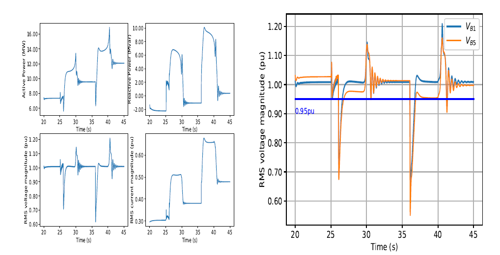
Figure 8 - IBR output and network rms voltage magnitudes during pick up of two induction motors
The 2.5 MVA motor draws around 6 Mvar of reactive power to start while the 3.0 MVA motor draws around 10 Mvar of reactive power. Further, although the motors start on no-load, since the mechanical load torque is proportional to the speed of the motor, the loading on the motor increases as the motor starts. This results in an increase in active power drawn from the IBR which further depresses the voltage at the load bus as shown in the figure. Here, although undervoltage is not an issue, there could be a cause for concern due to the voltage spike of around 1.2pu that occur at the instant the motors start.
The frequency derived by the PLL in the IBR control is shown in Fig. 9.
Here, the trajectory of frequency doesn’t seem to adhere to the same norm of frequency trends that appears in a system governed by rotating synchronous machines. Here, it appears that as the motors start, the frequency increases. Although at the moment there is no conclusive answer as to the reason for this behavior, few factors could be involved because this system is purely governed by IBRs. The first factor here is the method used by the PLL to track the angle of the grid, especially the orientation of the dq axis used for controlling the IBR. Secondly, when the motors start, they draw a tremendous amount of reactive power which could result in a slight advancement of the voltage angle due to the reduction in active power output. Third, the dynamics associated between induction motor behavior and IBR controls in a pure IBR system are yet to be fully characterized as there is no natural synchronous characteristic present in the system.
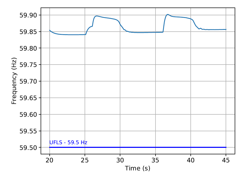
Figure 9 - Frequency derived by the PLL in the IBR control while first starting the 2.5 MVA induction motor followed by starting the 3.0 MVA induction motor
Investigation of this behavior is a topic for the future research. Although both the 2.5 MVA motor and the 3.0 MVA motor were successfully started, upon starting the 7.0 MVA motor, a voltage collapse was encountered. Thus, while picking up load in a system restoration study with IBRs, the characteristics of the motor loads that are present along with the time of their energization has to be considered. Often, control of loads to this granular extent may not be available and thus the rating of the IBRs have to be appropriately designed.
E. System restoration with two blackstart inverter based resources
As it was not possible to start all three induction motors using a single 25 MVA IBR (due to the reactive power demand from the motors), in this scenario, two 25 MVA IBRs are started up at the same time in different regions of the transmission network as shown in Fig. 10.
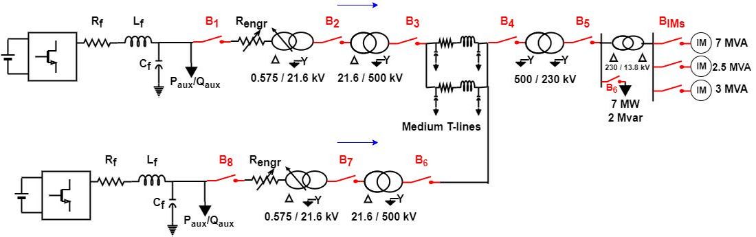
Figure 10 - Modified restoration path with two transmission connected inverter based resources participating in system restoration (blue arrows indicate direction of positive flow of power)
Both IBR facilities are considered to be identical in ratings and control mode. Further, the transformer connections of the second IBR facility is also considered to be the same as the first IBR facility. Both IBRs are started at t = 0.0s in constant current mode to serve their auxiliary loads. Then at t = 1.5s, their respective voltage and power control loops are enabled. From this point forward, the time instances of closing the breakers are different for both IBR facilities.
As before, breakers B1, B2, and B3 close at t = 6.0s, t = 7.0s, and t = 12.0s respectively. Now, at t = 15.0s, breaker B7 is closed to energize the 21.6kV/500 kV transformer of the second IBR while at t = 22.0s, breaker B8 closes to connect the second IBR to the energized transmission network and at t = 25.0s breaker B5 is closed. Here, ideally a synchro-check relay would be required in order to ensure minimal difference in voltage before closing the breaker B8. In this scenario, due to the low power output and the controller tuning, the relay was not required. The rms voltage observed at two ends of the transmission line (i.e. at breakers B3 and B7) and the active and reactive power contribution from each IBR facility to the system are shown in Fig. 11.
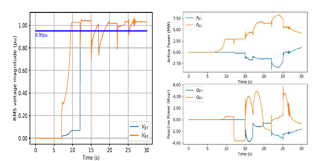
Figure 11 - RMS voltage magnitudes and active/reactive power at both ends of the transmission line when energized by two inverter based resources
Between t = 15.0s and t = 22.0s the active power through breaker B7 is negative as the first IBR facility serves the losses in the transformer between breakers B7 and B8. With both IBRs now energized to the network, the available rating is 50 MVA to start up the induction motors. However, again when all three induction motors were directly connected on-line at the same time, the two IBRs were still unable to start the motors and the voltage collapsed.
In some industrial facilities, three-phase induction motors could have controllable soft start schemes [24]. Here, by making use of a power electronic converter, the voltage at the terminal of the motor is controlled to bring about a gradual start. By utilizing this approach, the impact of motor starting on the power system can be minimized. To observe the impact of such a soft start scheme, all three induction motors are enabled with a soft start mechanism [24] and further, all three motors were started at the same time. The soft start mechanism is activated at t = 25.0s and it takes a couple of seconds to begin ramping the motor speed. The active and reactive power output from both IBRs, the active and reactive power drawn by the loads at the load bus, and the rms voltage observed at both ends of the transmission line along with the rms voltage observed at the load bus are shown in Fig. 12.
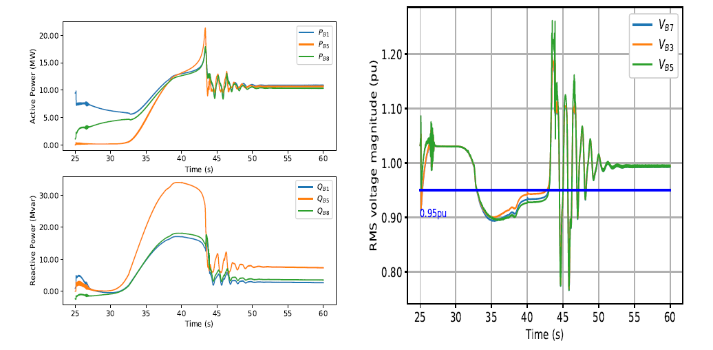
Figure 12 - Active/reactive power of both IBRs and load along with rms voltage when induction motors are energized by two inverter based resources
The total reactive power drawn by the loads is close to 35 Mvar to start up all induction motors. Further, once the motors are started, the loading level on the system is 10 MW, but each IBR also generates 10 MW to account for the auxiliary load and losses along the network. However, in this scenario, the voltage magnitude during the starting of the motors could also be a cause for concern which needs to be investigated further.
F. Combined industrial and distributed feeder load pickup
An additional scenario to consider is wherein both an industrial facility with three, three phase induction motors and a short distribution feeder (shown in Fig. 13) are connected at the same load bus.
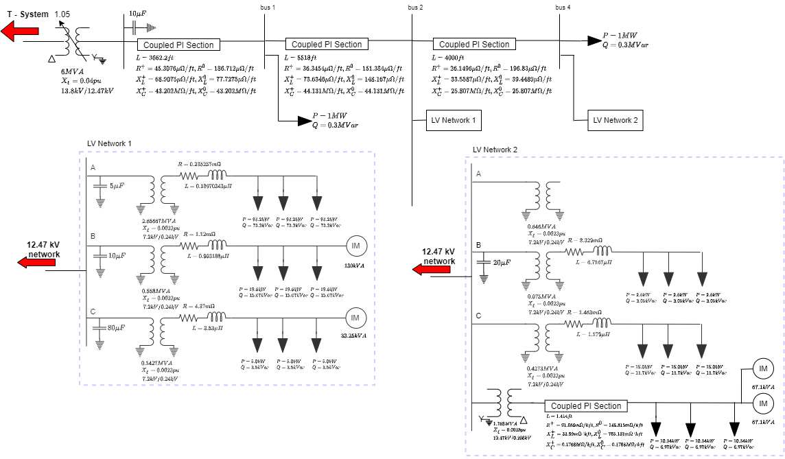
Figure 13 - One line diagram of distribution feeder
Such a scenario could be considered to be a case where an industrial facility (or critical load) has its main process run by the three phase induction motors, but there are balance of plant loads within the same facility which is represented by single phase induction motors and three phase induction motors of smaller rating. In this scenario, the distribution feeder would be picked up as cold-load but if there is insufficient isolation between the main three phase induction motors and the rest of the load within the plant, then there could be unstable interactions between the load elements.
An example of such unstable interactions is shown in Fig. 14 wherein the short distribution feeder load is picked up as soon as breaker B5 closes at t=25.0s while at t=26.0s, a soft start scheme of three large three phase induction motors is activated. Without the short distribution feeder, it is possible to successfully start up all three three phase induction motors with a soft start scheme. However here, the power electronic components of the soft start scheme of the three phase induction motors interact with the single phase induction motors to give rise to such an oscillatory behavior. In such an instance, more detailed studies and system planning is required to ensure that various dynamic components within the industrial facility do not interact with each other during the restoration phase.
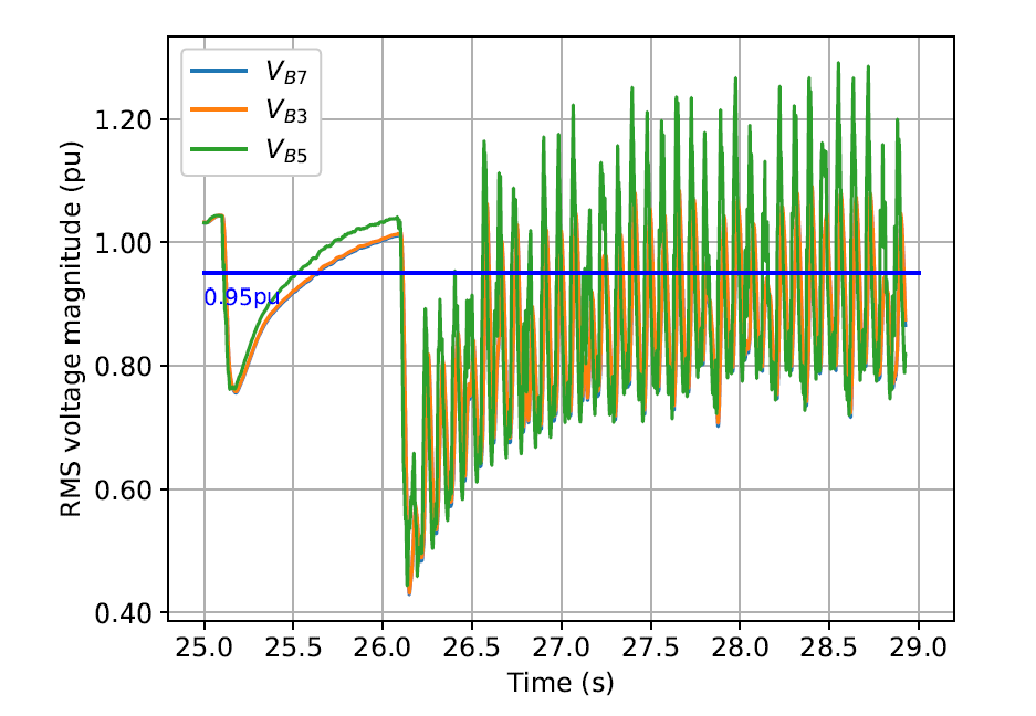
Figure 14 - Unstable interaction between the soft start mechanism of three phase induction motors and the single phase induction motors on the short distribution feeder
As the power electronic soft start scheme interacts with the single phase induction motors, the three phase induction motors can instead be started directly on-line, but in a staggered fashion. The 2.5 MVA three phase induction motor is energized first at t=26.0s while the 3.0 MVA three phase induction motor is subsequently energized at t=36.0s. The rms voltage observed at breakers B3, B5, and B7 is shown to the left in Fig. 15 while the active and reactive power output from both IBRs, and the active and reactive power drawn by the entire load measured at breaker B5 is shown to the right of Fig. 15.
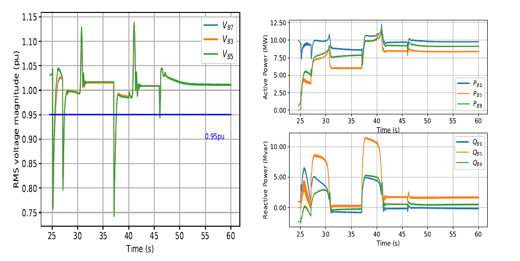
Figure 15 - RMS voltage magnitude and active and reactive power with short distribution feeder energized at t=25.0s, 2.5 MVA three phase induction motor direct-on-line start at t=26.0s, and 3.0 MVA three phase induction motor direct-on-line start at t=36.0s
From these scenarios, one can conclude that the characteristics of the load, and their method of control and operation can play a significant role in the stability of the system restoration process. Since traditionally distribution system restoration assumes that the transmission system is stiff and robust, such issues due to interaction between elements may not have been a cause of concern. Further, although the aim is serving critical facilities, additional load may need to be picked up either at the transmission system level or within the distribution feeder in order to increase the stability of the control loops.
5. Conclusion
It has been shown in this paper that a single IBR can be used in a black start sequence to energize transformers that have a rating 10 times the IBR rating. Furthermore, IBR controls that have a phase locked loop can be suitably designed and tuned to both form the grid and follow the grid at the same time. Energization of transmission lines and picking up of induction motor load has been addressed. The intricacies that surround the dynamic behavior of large three phase induction motors with the presence of smaller single phase induction motors has also been discussed. While designing a restoration plan, care must be taken to consider the dynamic characteristics of the load along with the control design of the IBR.
The merits of the proposed approach is to inform power system utilities that they may be able to leverage existing IBR resources for blackstart (if appropriate energy headroom is available) and may not have to wait for original equipment manufacturers (OEMs) to develop new control strategies. This is however not to be misunderstood as a generic conclusion but rather it is to be understood as a potential opportunity to make use of IBR flexibility and controllability.
However, this inference is not meant to be an all-encompassing statement but is rather meant to be illustrative of an entire realm of research work that can be delved into. In order to make such a control scheme work, it is important to completely understand the operation of the various control loops within the inverter and a system planner that receives a black box model may not have the ability to obtain such visibility. At the same time, a system planner should remain impartial to the exact form of control algorithm used within an inverter. Thus, while the controller of one OEM might work in standalone studies, more studies will be required to completely understand the restoration process.
Future work includes design of IBR control to accommodate suitable reaction to unbalanced faults along with exploration of the interaction between protection equipment and IBR controllers. Further, the application of the controller tuning rules and methods to IBRs of different ratings and various restoration paths will be explored. Additionally, as more substations are to be energized, there could be a requirement to carry out co-simulation studies between the distribution and transmission systems.
References
- “FERC-NERC-Regional Entity Joint Review of Restoration and Recovery Plans,” Federal Energy Regulatory Commission, Tech. Rep., Jan. 2016.
- North American Electric Reliability Corporation, “Reliability Standards for the Bulk Electric Systems of North America,” Jul. 2018.
- “System Restoration Procedure and Practices” CIGRE, Tech. Rep., Dec. 2017.
- M. Adibi et al., “Power system restoration - a task force report,” IEEE Transactions on Power Systems, vol. 2, no. 2, pp. 271–277, 1987.
- “EPRI Power System Dynamics Tutorial,” EPRI, Palo Alto, CA, Tech. Rep. 1016042, 2009.
- J. W. Feltes et al., “Some considerations in the development of restoration plans for electric utilities serving large metropolitan areas,” IEEE Transactions on Power Systems, vol. 21, no. 2, pp. 909–915, 2006.
- PJM, “Manual 36 : System Restoration ,” [Online]: https://www.pjm.com/-/media/documents/manuals/m36.ashx, June 2022.
- NYISO, “System Restoration Manual (Manual 20),” [Online]: https://www.nyiso.com/documents/20142/2923301/srp_mnl.pdf/4a4cb29a-f935-0714-b8be-5d7718bdcbc2, November 2019.
- G. Denis and T. Prevost, “MIGRATE WP3: Operating a System with 100% Power Electronics,” February 2019.
- R. Ierna, J. Zhu, A. Roscoe, M. Yu, A. Dys´ko, C. Booth, and H. Urdal, “Effects of vsm convertor control on penetration limits of non-synchronous generation in the gb power system,” in 15th Wind Integration Workshop on Large-Scale Integration of Wind Power into Power Systems as well as on Transmission Networks for Offshore Wind Power Plants, Nov. 2016.
- M.-S. Debry, G. Denis, and T. Prevost, “Characterization of the grid-forming function of a power source based on its external frequency smoothing capability,”[Online]: https://www.researchgate.net/publication/331714844 Characterization of the Grid-forming function of a power source based on its external frequency smoothing capability, pp. 1–6, March 2019.
- D. Ramasubramanian, Z. Yu, R. Ayyanar, V. Vittal, and J. Undrill, “Converter model for representing converter interfaced generation in large scale grid simulations,” IEEE Transactions on Power Systems, vol. 32, no. 1, pp. 765–773, Jan 2017.
- O. Bassey, K. L. Butler-Purry, and B. Chen, “Dynamic modeling of sequential service restoration in islanded single master microgrids,” IEEE Transactions on Power Systems, vol. 35, no. 1, pp. 202–214, 2020.
- Y. Zhao, Z. Lin, Y. Ding, Y. Liu, L. Sun, and Y. Yan, “A model predictive control based generator start-up optimization strategy for restoration with microgrids as black-start resources,” IEEE Transactions on Power Systems, vol. 33, no. 6, pp. 7189–7203, 2018.
- J. Li, H. You, J. Qi, M. Kong, S. Zhang, and H. Zhang, “Stratified optimization strategy used for restoration with photovoltaic-battery energy storage systems as black-start resources,” IEEE Access, vol. 7, pp. 127 339–127 352, 2019.
- C. L. Moreira, F. O. Resende, and J. A. P. Lopes, “Using low voltage microgrids for service restoration,” IEEE Transactions on Power Systems, vol. 22, no. 1, pp. 395–403, 2007.
- H. Jain, G.-S. Seo, E. Lockhart, V. Gevorgian, and B. Kroposki, “Blackstart of power grids with inverter-based resources,” in 2020 IEEE Power Energy Society General Meeting (PESGM), 2020, pp. 1–5.
- B. Badrzadeh and S. A. De Graff and P. Hinkel and L. Kothalawala and R. Liu and S. McGuinness and C. Noronha and D. Ramasubramanian and V. Singhvi, “Tools and techniques for system restoration,” CIGRE Science & Engineering, vol. 20, pp. 75–90, 2021.
- D. Ramasubramanian and W. Baker and E. Farantatos, “Operation of an all inverter bulk power system with conventional grid following controls,” CIGRE Science & Engineering, vol. 18, pp. 62–76, 2020.
- D. Ramasubramanian and E. Farantatos, “Viability of synchronous reference frame phase locked loop inverter control in an all inverter grid,” in 2020 IEEE Power Energy Society General Meeting (PESGM), 2020, pp. 1–5.
- Federal Energy Regulatory Commission, “Essential Reliability Services and the Evolving Bulk-Power System – Primary Frequency Response, Docket No. RM16-6-000, Order No. 842,” [Online]: https://www.ferc.gov/whats-new/comm-meet/2018/021518/E-2.pdf, Feb. 2018.
- D. Ramasubramanian, E. Farantatos, S. Ziaeinejad, and A. Mehrizi-Sani, “Operation paradigm of an all converter interfaced generation bulk power system,” IET Generation, Transmission Distribution, vol. 12, no. 19, pp. 4240–4248, 2018.
- Federal Energy Regulatory Commission, “Reactive Power Requirements for Non-Synchronous Generation, Docket No. RM16-1-000, Order No. 827,” [Online]: https://www.ferc.gov/whats-new/comm-meet/2016/ 061616/E-1.pdf,, Jun. 2016.
- Manitoba Hydro International Ltd. (MHI),PSCAD®, “Induction Motor Soft-Starter,” [Online]: https://www.pscad.com/knowledge-base/article/558, September 2019.