Electrical Power-transmission Grids: Future of High-voltage Power Line Carrier
Authors
A. G. MERKULOV - Siemens, Kazakhstan

Summary
This work focuses on the traditional type of telecommunications for electrical power-transmission grids. This corresponds to the high voltage (HV) power line carrier (PLC) communication along phase conductors of high, extra-high and ultra-high voltage electrical power-transmission lines (PTLs) of 35–765 kV. Twenty to twenty-five years ago, HV PLCs were used for most power transmission electrical lines in the electrical grid for the transmission of voice, telecontrol data and teleprotection signals. Despite the modernization of electrical equipment over the past 15–20 years, a large number of HV PLC channels (from a few hundred to tens of thousands) are still in operation, particularly in countries spread over a large area and possessing developed electrical grids.
The telecommunication networks of power-transmission companies are commonly based on the implementation of several technologies. The trends in the development of networks of power-transmission companies are currently oriented toward OPGW or wireless communications. Hence, the HV PLC technique has reached a milestone where the next stage of its lifecycle should be defined. This work analyses place of HV PLC technologies in the modern electric power industry in the next decades and aims to establish a strategy for future HV PLC application depending on the directions of telecommunication network development in power transmission companies.
This paper presents a time diagram showing the stages of introducing a new hardware and technology into PLC equipment and HV PLC technique, problems faced when extending existing HV PLC networks, such as spectrum overload and transition to packet switched IP networks, and the use of edge technologies such as discrete multi-tone modulation and the application of wideband digital power line carrier with packet switching to overcome these problems. As well, it discusses new areas of HV PLC technology application for long-term condition monitoring (CM) of power lines. Several strategies to facilitate and/or revive the application of HV PLC systems in the electrical grids of power-transmission companies are presented.
Based on the provided information, we can say that in the next decades, HV PLC, most likely, will not yield their positions in the industry. But HV PLC technologies can find their niche in the electric power industry of the future, even in the event of complete rejection of HV PLC channels for voice, data, and as technology for teleprotection and condition monitoring of HV electrical power lines.
Keywords
High Voltage - Power Line Carrier - Frequency Resource – Modem - Condition Monitoring1. Introduction
The telecommunication networks of power-transmission companies are commonly based on the implementation of several technologies. The current trends focus on the installation of optical ground wires (OPGWs) and different multiplexing equipment. Moreover, an active transition from the synchronous digital hierarchy technology to packet-switched networks based on the multiprotocol label switching transport profile (MPLS-TP) and internet protocol MPLS (IP-MPLS) technologies that offer high-speeds from tens to hundreds of gigabits per second is currently underway.
This paper focuses on the traditional type of telecommunications for high-voltage (HV) electrical power-transmission grids. This corresponds to the HV power line carrier (PLC) communication along phase conductors of electrical power-transmission lines (PTLs) of 35– 765 kV. HV PLCs are used in power-transmission companies for dispatching voice communication, telecontrol and metering data transmission, and transmission of relay protection signals (teleprotection) between HV substations (SSs), as an HV PTL is generally the shortest path between two SSs. The term PLC is also applied to modems used in medium-voltage (MV; 10–20 kV) and low-voltage (LV; 0.4 kV) electrical networks. This often causes confusion because these are different technologies with few commonalities.
HV PLCs were used for most PTLs in the electrical grid 20–25 years ago. Despite the modernization of electrical equipment over the past 15–20 years, a large number of HV PLC systems (from a few hundred to tens of thousands) are still in operation, particularly in countries spread over a large area and possessing developed electrical grids.
The information pertaining to applied technologies, modern HV PLC equipment architecture, high-frequency (HF) path parameter calculations, and the design of HV PLC channels has been reported in [1]. Additionally, an investigation into the role of HV PLC in packet-switching networks is reported in [2]. However, future strategies concerning HV PLC application in modern power-transmission grids are not reported in available literature. This topic has been discussed from time to time at closed colloquiums of the International Council on Large Electric Systems (CIGRE). However, there is no common opinion in academia or in the industry regarding this issue. The number of specialists familiar with these technologies has been gradually decreasing. The author’s view on the discussed problem is based on 15 years of practical experience and theoretical research in HV PLCs.
Given all the factors mentioned above, it will be interesting to see what the future holds for HV PLC technologies. The trends in the development of networks of power-transmission companies are currently oriented toward OPGW or wireless communications. Hence, the HV PLC technique has reached a milestone where the next stage of its lifecycle should be defined.
This paper analyzes the current state of the HV PLC technique, the problems faced when extending existing HV PLC networks, and the use of edge technologies to overcome these problems. This work aims to establish a strategy for future HV PLC applications. Will HV PLC have a place in the modern electric power industry in the next few decades, or will this century-old technology disappear?
2. The history of HV PLC development and its current state
The main features of HV PLC are detailed here to establish a basis for further discussion. The theory of electromagnetic wave propagation along multiconductor power lines was proposed by J. Carson in 1926 [3]. Most studies that have attempted to calculate HF-path parameters such as frequency response, group time delay, and input impedance and develop the theory of HF-signal propagation have been conducted in 1930–1970 by J. Fallout, G.E. Adams, F.C. Krings, L.M. Wedephol, C.H. Garry, Y.P. Shkarin, M.V. Kostenko, etc. [4-9]. Contemporary authors are S. Cristina, M. Zajc, N.Suljanovic, A. Mujcic, R. Piggy, R. Raheli, E. Fortunato, A. Raviola, etc. [10-15].
In most countries, the frequency range of HV PLC is 40–500 kHz, with frequency multiplexing for all channels. In some countries, the spectrum is expanded to 1000 kHz. Typically, in each transmission direction, each channel has its own operating band of n × 4 kHz. For example, the value of n equals 2 and 3 for the 100–108 kHz and 140–148 kHz bands, as well as the 200–212 kHz and 240–252 kHz bands, respectively. Single purpose teleprotection HV PLC channels operate in 2 kHz bandwidth as well. The peak envelope power of a transmitter is limited to 100 W. PLC channels operate on HV lines with lengths ranging from tens to hundreds of kilometers. HV PLC channels follow a point-to-point topology.
The advantages of HV PLC over other types of communication are the high mechanical durability of the power line as a transmission medium, the low cost of construction, simple installation, and low capital cost for maintenance. HV PLC equipment can transmit information (in the HF-signal form) over hundreds of kilometers without repeaters. The longest overhead lines equipped with an HV PLC channel had a length of more than 1000 km. Owing to its multimodal nature, the HF-signal propagates along all the phase conductors of PTL and earth wave, and the HV PLC channel can stay in operation even when the phase conductors or towers of PTL break down. The main disadvantage of this technology is its sensitivity to weather conditions, particularly in the event of icing of the PTL phase conductors. For coupling to phase conductors of PTL, capacitive voltage transformers (or line capacitors) and line matching units are used. To avoid the loss of HF signals on electrical SS bars, line traps are used. There are two main coupling schemes – phase to ground and phase to phase.
Attenuation and noise levels of the HF path are strongly dependent on the weather conditions and can vary in a range of tens of decibels. It causes a change in the signal-to-noise ratio (SNR). The influence of various parameters of overhead line construction, tapping lines, HF bridges, underground cable junctions, and ice coating on the attenuation of the HF path has been described in detail in [1,16]. The main source of noise in the HF path is the phenomenon of corona–air discharges near the surface of phase conductors. Corona noise differs from additive white Gaussian noise (AWGN). To achieve the same bit rate in the presence of corona noise, a higher signal-to-noise ratio is required as compared to AWGN, and a special corona factor should be considered in the HF path calculation. The corona factor equals 0, 2, 6, and 9 dB for 35-, 110-, 220-, and more than 220-kV transmission lines, respectively [1]. Figure 1 illustrates the structure diagram of the HV PLC channel and an example of SNR change during periods of good and foul weather conditions.
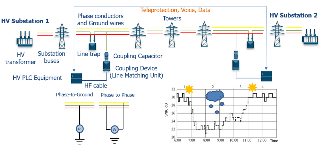
Figure 1 - Structure diagram of HV PLC channel
Figure 2 presents a time diagram showing the stages of introducing new hardware and technologies into PLC equipment. The existing HV PLCs date back to the 1930s. Subsequent systems were based on valve technology. In the late 1960s and early 1970s, there was a transition to transistors. Since the mid-1990s, digital signal processors (DSPs) have been widely used in PLC equipment. The use of valve and transistor technologies allowed the transmission of information signals using analog modulation methods, such as single-sideband (SSB) amplitude modulation and frequency shift keying. In the HV PLC terminology, such channels are called analog PLC (APLC) channels, which are based on the frequency division of information signals. With the advent of the DSPs, it became possible to use digital modulation in PLC equipment, such as quadrature amplitude modulation (QAM), trellis coded modulation (TCM), and orthogonal frequency division multiplexing (OFDM). This technological transition has effectively taken the PLC communication to a new stage of evolution. The HV PLC equipment uses time-division multiplexing and digital-modulation methods called digital PLC (DPLC). The architecture of modern HV PLC systems complies with IEC 62488-1, IEC 62488-2, and IEC 62488-3 standards. In the last few years, a new generation of HV PLC technologies were introduced – digital PLC systems based on discrete multi-tone modems and power line condition monitoring. These topics will be discussed in the next chapter.
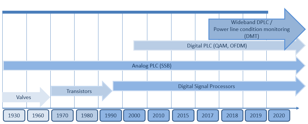
Figure 2 - The stages of HV PLC equipment development
The HV PLC channels, which are exclusively used in communication and/or teleprotection applications, are called single-purpose channels. However, the teleprotection signals are typically transmitted in the same band as voice or data service with interruption of this service during the trip-signal transmission time (few tens of milliseconds). Teleprotection signals are transmitted using a single frequency or dual frequency code at the peak envelope power of the transmitter.
The main characteristics of traditional HV PLC equipment are symmetric n × 4 kHz operating bands, use of multiplexers for frequency (FDM) and time division (TDM) of signals, use of analog 2- and 4-wire voice interfaces, connection to various remote terminal units via RS-232 and external multiplexers via X.21 interfaces, and a built-in Ethernet bridge. Channels with a bandwidth of up to 12 kHz are the most common. DPLC equipment modems are based on QAM, TCM, and OFDM modulation. The typical spectral density of modems in real channels is 4 and 8 bit/s/Hz in adverse and good weather conditions, respectively. Therefore, the speed of DPLC channels is not more than 100 kbps depending on the modem bandwidth and line parameters. Information regarding HV PLC networking can be found in [17–19].
In general, there are two problems that cause difficulties in operating existing HV PLC channels and creating new ones. The first is the transition from legacy networks with analog voice transmission and low-speed data interfaces to IP-based networks. HV PLC equipment should comply with new industrial requirements. However, it is difficult to provide all services based on IP with the same operating band owing to the large overhead volume of IP packets [19]. Although one might reckon that extension of the operating band could resolve the above problem, realization of the same is not straightforward. Let us see why.
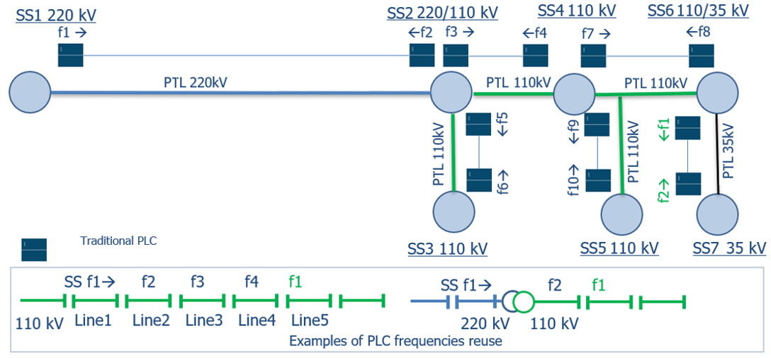
Figure 3 - HV PLC frequency reuse principles
The HF-signal wavelengths range from 0.5 to 10 km. Therefore, HF signals spread far beyond the borders of the line on which the HV PLC channel is set up. This happens due to the connection between the PTLs and the SS buses, as well as in cases of parallel routing. The HV PLC frequencies can be reused after a certain number of PTLs as well as changes in their voltage class. This is regulated by IEC 62488-1 and IEEE 643 standards. Figure 3 shows an example of HV PLC frequency reuse. At SS1, the farther the SS location, the lower the HV PLC HF-signal level on this line. The HF-signal levels of frequencies f1 and f2 on the line joining SS1 and SS2 are negligibly low compared to the line joining SS6 and SS7. Therefore, they can be reused.
3. The newest trends in HV PLC technologies and development
Let us discuss the new achievements in HV PLC technique, which help overcome the problems of the transition to IP-based networks and HV PLC frequency selection. The best solution is the implementation of discrete multi-tone modulation (DMT) [20] in digital PLC equipment and the development of a new subclass of wideband DPLC systems (W-DPLC) with packet switching [21]. This facilitates the creation of channels with operating frequencies of hundreds of kilohertz, notching of unwanted frequency bands, composition of the necessary bandwidth from several frequency bands, creation of asymmetric transmission bands, and frequency-resource redistribution between W-DPLC [22]. The W-DPLC system processes IP traffic to provide packet prioritization and reduce the volume of overhead information. Function of header compression is mandatory. Application of such header compression techniques as robust header compression (ROHC), robust header compression TCP-profile (ROHC-TCP) and additional compression of Layer 2 header allows to reduce frame headers size from tens bytes to few bytes and provide high efficiency of information transmission close to traditional TDM multiplexors. Figure 4 shows the concept of the W-DPLC system with DMT modems when it supersedes a few traditional HV PLC.
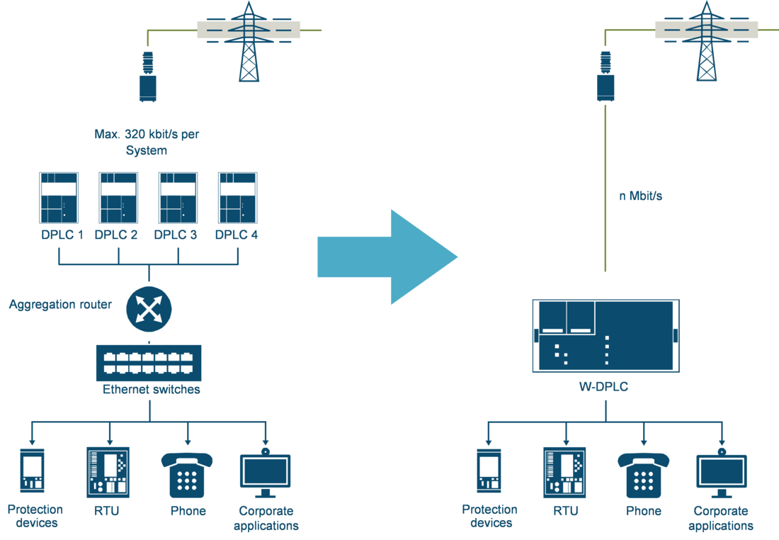
Figure 4 - Consolidation of a few traditional HV PLC capacities into one W-DPLC system
The results of field trials, as reported in [23], reveal the high performance of W-DPLC systems. These experiments were performed considering a 110-kV overhead power line with two HF bridges and a tap line. Figures 5, 6 present HV PLC spectrum diagrams for different operating bands of W-DPLC systems without notching and with notching, respectively. Attenuation of overhead PTL differs from 27 to 42 dB depending on frequency – 27 dB in the range near 200 kHz and more than 42 dB in range near 500 kHz. The transmission rate of modems is shown in the right part of the diagrams. A bit rate of more than 0,8 Mbps was achieved during the tests, which is impossible when using a traditional DPLC.
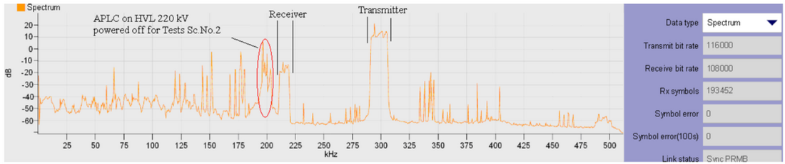
Figure 5 - Spectrum diagram of a W-DPLC system without notching (Test 1)

Figure 6 - Spectrum diagram of a W-DPLC system with notching (Test 2)
Asymmetric transmission bands are useful for the transmission of IP traffic because mainly data is from the SS to the dispatch center. Hence, a large bandwidth is required in this direction. In addition to efficient use of spectrum, it provides low latency, header compression of an IP packet and packet prioritization. All these are key features for the resolution of the two problems in HV PLC communications described previously.
Notching of specified frequencies and bands occupied by radio stations or other HV PLC channels allows for the creation of composed operating bands and effective spectrum utilization. Figure 7 presents the already known scheme from Figure 2 but with a new substation connected to SS1 and a new HV PLC channel based on W-DPLC systems with DMT modems. As it can be seen, the transmission band from SS1 to the new substation is composed of 3 parts located in different ranges of the HV PLC spectrum.
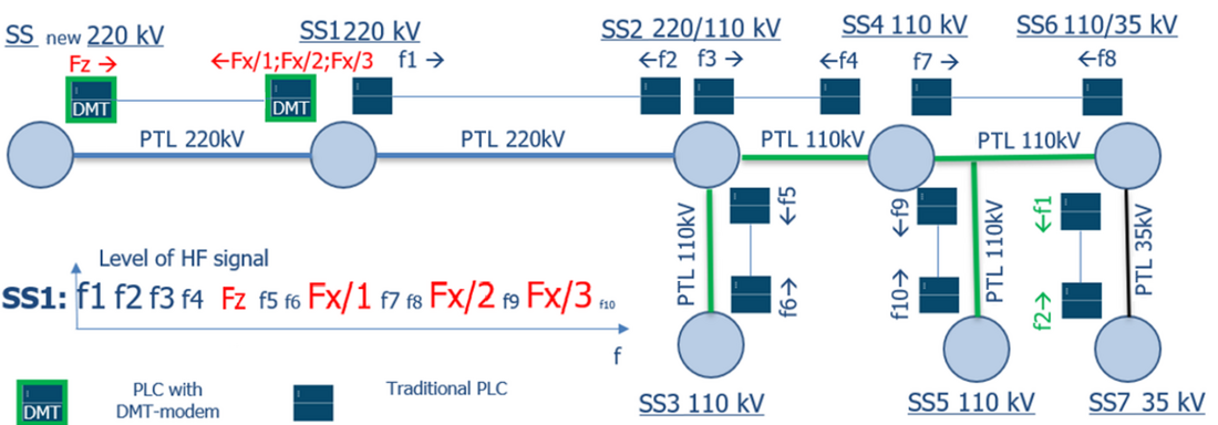
Figure 7 - Princeples of application of composed frequecny bands for W-DPLC systems with DMT modems
Other innovations concerning the HV PLC technique are also based on the use of multi-tone signals. These include reflectometric monitoring or long-term condition monitoring (CM) of power lines. The use of such systems identifies the location of mechanical damage to the line in advance, preventing accidents. Information about the use and features of CM can be found in [24]. PLC technology is the only one that allows you to define the location of the mechanical fault in the power line. Figure 8 the presents concept of a CM application. The big benefit of CM systems is that they can be coupled to an HV line with the same coupling devices as HV PLC equipment.
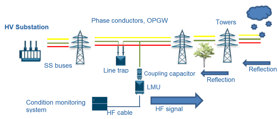
Figure 8 - Concept of condition monitoring system application
The principle of PTL monitoring is based on a comparative analysis of the characteristics of discontinuities in it over a long period of time. When a predetermined deviation in the wave characteristics of the PTL is detected, CM generates a warning signal to the telecontrol system of SS. Figure 9 presents the reflection diagram of the HV PTL from the long term condition monitoring system. The grey graph corresponds to the normal condition of PTL: the peak at 190 km corresponds to the end of the line. The orange graph corresponds to a faulty condition of the PTL with grounding of the phase conductor at 116,6 km of PTL.
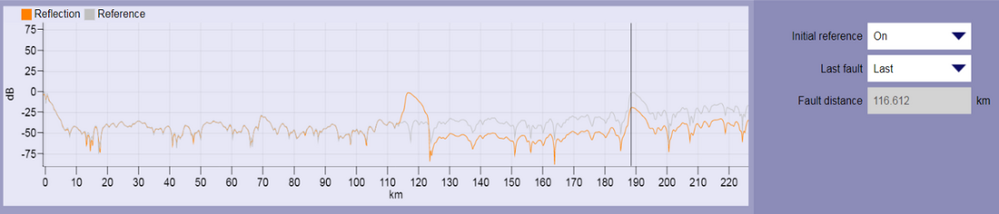
Figure 9 - Reflection diagram of PTL with indication of place of fault.
The main problem with the deployment of CM channels is the need for a large frequency band in which the multi-tone signal is transmitted. The wider the frequency band, the higher the accuracy of locating the fault. The systems of reflectometric CM of power lines make it possible to identify issues such as poor-quality installation at the junctions of phase conductors, wire breaks, and areas of icing. The theoretical operating range of the monitoring system is several hundred kilometers and is dependent on the frequency range used. The monitoring device is installed on each phase of the PTL, while for coupling to the line, the same coupling equipment—line capacitors, line traps, and line-matching units—is used as for other HV PLC channels.
4. The place of HV PLC technologies in future power-transmission electrical grids
Let us consider three means (or options) to facilitate the continuous use of HV PLC equipment and technologies in modern power-transmission applications.
Option No. 1: Complete transition to the use of fiber-optic lines and OPGW. In this case, the old HV PLC channels are either completely decommissioned or replaced. This approach has been followed in Saudi Arabia, Japan, and most of Western Europe.
Option No. 2: PLC channels are used along with the fiber-optic lines in the same communication network as a backup for mission critical signals—dispatching voice, telecontrol, and teleprotection. This is a good option for electrical systems with a historically large number of HV PLC channels, large territory, and branched topology. PLC channels are used mainly for teleprotection purposes on high voltage lines of 220 kV or higher. In 35 and 110 kV electrical grids, PLC channels remain in wide demand for voice communications and data transmission.
Option No. 3: Only the main transmission lines are equipped with OPGW, and the remaining communication network is based on HV PLC systems. This is a typical scenario for electrical grids in countries with underdeveloped electrical grids or those with large territories and small numbers of SSs and PTL.
Furthermore, all these options are analyzed to see what benefits the use of HV PLC can bring.
At first glance, HV PLC technologies corresponding to option No. 1 have been completely exhausted, and no further development or application of these systems can be foreseen. However, if all HV PLC channels became obsolete and replaced by other communication types, all HV PLC frequency resources would become available for use. Therefore, such electrical grids are the most suitable for deploying CM channels for PTL monitoring. The application of CM systems can improve the reliability of electric grids by preventing the occurrence of faults due to different factors, as well as reducing the time and cost of fault localization.
Figure 10 illustrates an electrical grid wherein the communication network comprises OPGW and multiplexers, and the main transmission lines are equipped with HV PLC CM systems.
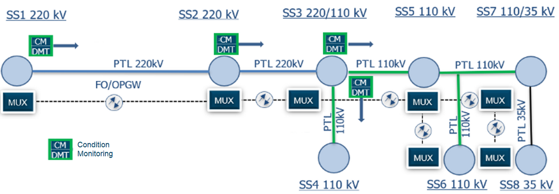
Figure 10 - Application of CM systems to the electrical grid with communications based on OPGW and MUXs
Although most modern electrical grids are equipped with OPGWs and multiplexers, there are some remote SS locations where OPGW construction and/or wireless communication are not feasible due to cost and/or architectural difficulty An appropriate example of this corresponds to the installation of OPGW on the existing transmission lines through forests and mountains. In such networks, HV PLC systems can be used as a last-mile solution for voice- and data transmission via creation of HV PLC “islands.” When SSs are separated from each other by many PTL, absence of mutual interference between HV PLC channels is guaranteed. Figure 11 depicts an electrical network diagram comprising an HV PLC “island.”
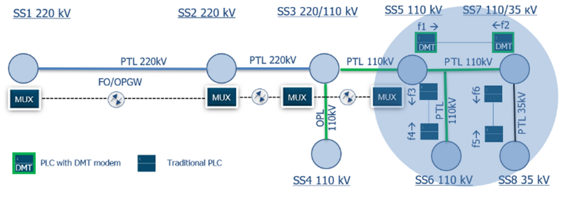
Figure 11 - Electrical network diagram comprising an HV PLC “island”
The HV PLC systems facilitate the transmission of different types of information from remote SSs located tens or hundreds of kilometers away from the “main” electrical grid, and moreover it can be used as redundant path for teleprotection commands transmission if voice and data services have being done via other type of communications.
Option 2 is the most complicated because it requires the creation of new HV PLC channels and the modernization of existing ones in networks comprising hundreds or thousands of HV PLC channels. This is done to ensure that the HV PLC frequency resources can be utilized effectively. This situation is generally true of grids, all of whose frequency resources have been nearly consumed owing to their large HV PLC channel count.
For example, HV PLC systems based on DMT modems are the most suitable for use in networks faced with the problem of efficient use of frequency resources. As mentioned before, using DMT modems, the required frequency band can be put together from separate free narrow bands, and hence, the operating bands can be asymmetrical. Figure 12 shows a part of a HV PLC spectrum, where the operating band in one direction is WTX1= 16 kHz, and it is a set of three parts: WTX1.1 = 8 kHz and two 4 kHz bands WTX1.2 and WTX1.3. In the reverse direction, it is a single band (WTX2, = 8 kHz). The peaks in the spectrum correspond to the carrier frequencies of the neighboring HV PLC channels.
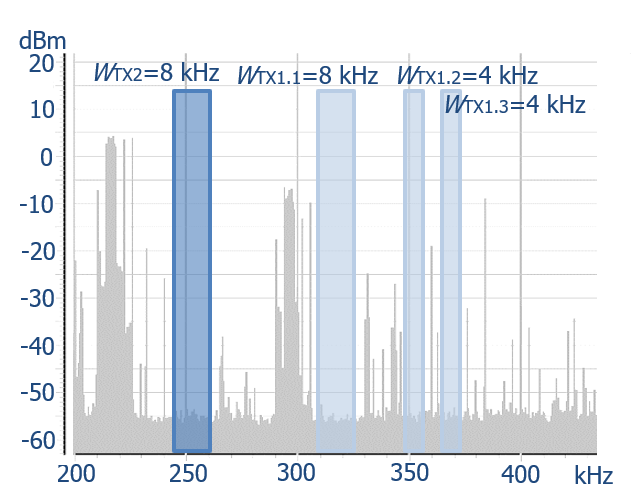
Figure 12 - Principle of using the composite operating band of HV PLC with DMT modems
The HV PLC technology is an inherent part of such networks, and therefore, it holds significance in their design and development. This state is not expected to change over the next decade. However, the problem of the deficit of the frequency resources, which in some cases makes it impossible to design new channels, will have an increasing bias toward option No. 1 of the communication network. Because the process to change all HV PLC links to other technologies is slow and costly, the use of CM systems for PTLs in such networks seems almost impossible in the next decade due to the lack of free frequency bands.
In option No. 3, there are a fewer number of PTL, and most of them are equipped with HV PLC channels. Only the main lines with a relatively short length (around a few tens of kilometers) have OPGW installed and multiplexers as the core network. Because of the high cost of OPGW construction, an HV PLC network will be used as the main communication path for all lines, excluding the main lines.
In this case, sufficient HV PLC frequency resources are available for creating new channels. The basic strategy for the application of HV PLC systems is the creation of new channels in parallel with existing channels and using the existing channels as a back-up. It means, if we have old HV PLC channel and want to create new one, we should not stop operation of existing systems. We will use old one as back-up and new one as main route for redundancy, especially for teleprotection. This increases network reliability. A good example of the implementation of this strategy is the project undertaken to modernize the HV PLC channels in Mongolia.
Let us consider a special variant of the HV PLC application showed in Figure 13. The following scenario can be called extraordinary, but it is still possible. In the event of the crash of towers owing to the occurrence of a disaster, that causes the breakage of fiber-optic communication lines, the electrical grid would operate without communication channels. Naturally, the power supply to critical facilities must be restored first. The restoration of the transmission line itself is a difficult task, but it can be solved by simple technical means. Repairing OPGW requires specialized equipment, such as optical cables and muffs, and the involvement of highly qualified specialists. In contrast, in the presence of a ready SS infrastructure, HV PLC channels can be deployed in a short time to transmit the required minimum critical information and teleprotection signals. This strategy requires retaining previously installed HV PLC equipment at SSs or creating a separate HV PLC network, which can be frozen before it is needed.
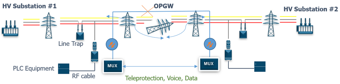
Figure 13 - HV PLC application as “Emergency communications”
5. Conclusion
This paper presents several strategies to facilitate and/or revive the application of HV PLC systems in the electrical grids of power-transmission companies. The HV PLC technology can be used in condition-monitoring systems installed on electrical grids along with other communications systems. The modern DMT-modem-based HV PLC systems can resolve the problems associated with the HV PLC frequency-resource deficit in networks containing a large number of HV PLC channels. This can be accomplished by applying the strategy of composite operating bands. The application of HV PLC communication channels in electrical grids with communications based on HV PLC can be realized by operating new channels alongside existing ones, thereby improving network reliability. The HV PLC channels can be used as emergency communication equipment and maintain the safety of the electrical grid in the event of disasters or catastrophes. In the next few decades, HV PLC, most likely, will not yield their positions. But HV PLC technologies can find their niche in the communications of the power-transmission industry of the future, even in hypothetical complete rejection of HV PLC channels for voice, data, and teleprotection as technology for condition monitoring of HV electrical power lines.
References
- A. G. Merkulov, Y. P. Shkarin, S. E. Romanov, V. A. Kharlamov, Y. V. Nazarov, "High Voltage Digital Power Line Carrier Channels", Switzerland: Springer Nature AG, 2021.
- A. Mujĉiĉ, N. Suljanoviĉ, M. Zajc, J. F. Tasiĉ, "High-voltage PLC roles in packet-switching networks of power utilities," 2007 IEEE International Symposium on Power Line Communications and Its Applications, 2007, pp. 204-209.
- J. R. Carson, "Wave propagation in overhead wires with ground return," in The Bell System Technical Journal, vol. 5, no. 4, Oct. 1926, pp. 539-554.
- J. Fallou, "Propagation des courants de haute frequency poplyphases le long les lines aếrienne de transport l’ếnergie". Bulletin de la Sosiete Francaise des Electriciens, Aout, 1932, pp. 332-348.
- L.M. Wedepohl, "Application of matrix methods to the solution of travelling-wave phenomena in polyphase systems" Proc. IEE, vol. 110, Dec. 1963, pp. 2200-2212.
- L.M. Wedepohl, Wave Propagation in nonhomogeneous multiconductor systems using the concept of natural modes. Proc. IEE, vol. 113, 622-626, Apr. 1966
- L.M. Wedepohl, R.G. Wasley, "Propagation of carrier signals in homogeneous, nonhomogeneous and mixed multiconductor systems". Proc. IEE., vol. 115, 179-186, Jan. 1968.
- M.V. Kostenko, Y.P. Shkarin, "Calculation of HF path parameters along power transmission lines". Newsteller of USSR Academia of Sciences, Power and Transport, Moscow, №1, 1967, pp. 71-78.
- M.V. Kostenko, L.S. Perelman, Y.P. Shkarin, "Wave processes and electrical disturbances in multi conductor high voltage electrical power transmission lines" (in Russian), Moscow: Energy, 1973.
- P. Burrascano, S. Cristina, and M. D'Amore, "Performance evaluation of digital signal transmission channels on coronating power lines," in ISCAS'88, 1988, pp. 365-368.
- A. Mujčić, N. Suljanović, M. Zajc, J. F, Tasič, J.F, "Corona noise on a 400 kV overhead power line: Measurements and computer modeling", Electrical Engineering vol 86(2), Jul. 2004, pp. 61-67
- A Mujčić, N.Suljanović, M Zajc and J. F. Tasič, "Detection of nonlinearities in communication channel phase characteristics", 11 International Electrotechnical and Computer Science Conference ERK, Portorož, Slovenia, 2002, pp 175-178.
- N.Suljanović, A Mujčić, M Zajc and J. F. Tasič, "Power line tap modeling at power-line carrier frequencies with radial-basis function network". Engineering Intelligent Systems vol.11, No. 1, pp 9-17, 2003.
- R. Pighi and R. Raheli, "Linear Predictive Detection for Power Line Communications Impaired by Colored Noise," 2006 IEEE International Symposium on Power Line Communications and Its Applications, Orlando, FL, USA, 2006, pp. 337-342
- Pighi, M. Franceschini, G. Ferrari and R. Raheli, "Fundamental Performance Limits for PLC Systems Impaired by Impulse Noise," 2006 IEEE International Symposium on Power Line Communications and Its Applications, Orlando, FL, USA, 2006, pp. 277-282.
- REA Bulletin 66-5. "Power system communications: power line carrier and insulated static wire systems," Energy Management and Utilization Division Rural Electrification Administration, U.S., Government Publications, 1978, pp. 78-22742.
- E. Fortunato, A. Garibbo, L. Petrolino, "An experimental system for digital power line communications over high voltage electric power lines – field trials and obtained results," 7th ISPLC Symposium, Kyoto, Japan, 2003, pp. 26-31.
- A. Raviola, G. Garoti, "Reliable architecture for power system operational communications integration of digital PLC & ATM," CIGRE D2 Colloquim B03, Brasil, Rio de Janeiro, 2003, pp. 71-80.
- A. G. Merkulov and V. P. Shuvalov, "Analytical study of principles organization of convergent packet DPLC networks with transition from Frame Relay to IP technology on the examples of projects implemented in Kazakhstan," 2015 International Siberian Conference on Control and Communications (SIBCON), Omsk, Russia, 2015, pp. 1-10.
- R. Pighi and R. Raheli, "On multicarrier signal transmission for high-voltage power lines," International Symposium on Power Line Communications and Its Applications, Vancouver, BC, Canada, 2005, pp. 32-36, doi: 10.1109/ISPLC.2005.1430460.
- A. G. Merkulov, R. Adelseck and J. Buerger, "Wideband digital power line carrier with packet switching for high voltage digital substations," 2018 IEEE International Symposium on Power Line Communications and its Applications (ISPLC), Manchester, UK, 2018, pp. 1-5.
- J. Kussyk and R. Adelseck, "Cooperative reuse of fragmented spectrum in high-voltage power-line carrier systems - a new approach of PowerLink IP," 2019 1st Global Power, Energy and Communication Conference (GPECOM), Nevsehir, Turkey, 2019, pp. 41-45.
- A. G. Merkulov, R. Frankenberg and J. Kussyk, "Distinctive features, characteristics and field tests of the W-DPLC systems," 2019 1st Global Power, Energy and Communication Conference (GPECOM), Nevsehir, Turkey, 2019, pp. 80-85.
- Condition Monitoring for High Voltage Transmission Lines or Cables. White paper. Siemens AG, Smart Infrastructure, 2020.
Biography
Anton G. Merkulov, PhD, Member CIGRE WG D2.44, Senior Member IEEE. He studied Telecommunication Technologies in Almaty University of Power Engineering and Telecommunications, graduated with Dipl.-Ing. Degree in 2007. In 2015 he completed his PhD in Telecommunications in Ufa State Aviation Technical University. He began his carrier in Siemens Kazakhstan branch office since 2007 as a commissioning engineer of high voltage power line carrier communications. Since 2017 he is head of Smart Communications business unit and technical expert in telecommunications. He has more than 15 years of work experience in telecommunications for power transmission companies with focus to high voltage PLC, and is the author of two books and more than 30 papers about high voltage PLC.