Improving the Utilization of Distribution Transformers Supplying Public Electric Vehicle Charging Installations: A New Zealand Case Study
Authors
D. MARTIN - ETEL Transformers Ltd, NZ.A2 convener, Auckland, New Zealand
R. WATSON - Northpower Ltd, NZ.A2 member, Whangārei, New Zealand

Summary
In New Zealand there is a broad strategy by the government to decarbonize. Already, around 80% of the electricity generated is from renewable sources [1]. Next, the electrification of transport is seen as a priority by the energy sector [2]. One way to promote uptake is to install more public EV (electric vehicle) chargers to resolve ‘range anxiety’ concerns. These chargers differ from the home-type in that they are designed to be quick, and therefore they have a substantial power rating e.g. several 100 kW. For the distribution network operator, this power requirement is substantial compared to a distribution transformer having a rating of a few 100 kVA.
A utility being able to improve the utilization of assets is highly desirable to maintain network affordability. Currently, a utility may reserve transformer kVA capacity for the EV charger. However, at present the proportion of EVs on NZ roads is around one percent [2]. Reserving capacity before there is a lot of charging is inefficient as it could drive unnecessary transformer upgrades, or cap the placement of EV charger installations. A better option could be to monitor online an existing transformer and safely allow it to momentarily operate higher than its rated load for short periods of the day, until community charging behaviour is better understood and planned for. IEC loading guide 60076/7 already permits cyclic loading past nameplate rating.
This article presents proof of concept using load data from a local public EV charger, which will show how different charging patterns will impact the life of two existing distribution transformers. LV monitoring was attached to measure load online. Thermal modelling was performed to track long-term ageing of insulation, and use this to indicate when the transformers should be replaced. The thermal simulations were also used to model the N-1 capability of the distribution substation if one transformer were offline.
Keywords
Transformer – Thermal response – IEC 60076-7 – EV Charging1. Introduction
Many utilities and organisations are looking to install EV chargers into distribution networks. Usually, the network owner will require that the existing transformer has enough current carrying capacity to supply both the existing load and the new charger at full output. Unfortunately, this acts as a barrier to charger uptake if the utility does not see business value in upgrade investment, such as a higher capacity transformer and associated electrical work. However, while the number of EVs in New Zealand is relatively low compared to petrol or diesel driven vehicles, it is unlikely that a charger will be used at full power continuously. A solution could be to safely operate the transformer higher than its rated load during peak-charger usage, where the transformer is given sufficient time to cool down between uses and over night when there is minimal load. Some advantages of this approach are:
- Transformer capacity upgrade is driven by actual EV charging patterns. While the number of charge cycles is low, the asset can be better utilized which is preferable to the customer and utility in the long run.
- Lowers entry barriers to EV charger installation if substation capacity upgrades are not required.
- Helps utilities manage the uncertainty of EV uptake by the community, the utility keeps their existing assets in service for as long as possible until upgrades are driven by need.
It is recognised that once EV usage becomes mainstream the transformers may not be given sufficient time to cool. This loading strategy is intended to be an interim measure to reduce entry barriers by increasing the utilization of the existing network as much as possible.
A transformer is given operational temperature limits. The volume of oil results in a large thermal inertia, so it takes many hours to heat up and reach a stable temperature. A typical EV fast-charge cycle is complete in an hour, where the transformer temperature will not rise significantly due to the thermal inertia. Relying on this heating and cooling cycle while the daily number of EV charges is low deserves further investigation, and then a substation upgrade undertaken in the future once the charging load has reached a certain threshold.
A case study about operating transformers at higher loads is given in this article, by simulating the behaviour of two 500 kVA transformers supplying a four-EV charging station in Whangārei. This charging station is shown in Figure 1 along with the distribution substation housing these two transformers in the background.
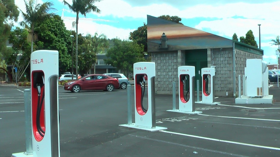
Figure 1 - EV charging stations with distribution substation housing two 500 kVA transformers in background
2. Transformer loading
Various loading limits are described in the IEC 60076 series of transformer standards: nameplate rating, normal cycling rating, long-time emergency rating and short-time emergency rating (given in Table 1). A transformer designed in accordance with IEC 60076/2 [3] will, at rated load, have an ultimate maximum top-oil and winding temperature rises of 60 K and 65 K above ambient.
| Current limit (p.u.) | Winding hot-spot (°C) | Top-oil temperature (°C) |
|---|---|---|---|
Normal cyclic loading | 1.5 | 120 | 105 |
Long-time emergency loading | 1.8 | 140 | 115 |
Short-time emergency loading | 2.0 | None | None |
Normal Kraft paper insulation will take one year to degrade when heated continuously to 98 °C in air, and having 2% water content [4]. The winding temperature rise limit is set based on this 98 °C one-year lifetime, using a 25°C ambient temperature, a 65 K rise, and a few degrees extra rise allowed for possible hot-spots.
The rate of ageing of Kraft paper doubles for every increase in 6 °C around the operating temperature range of a transformer. A normalised rate of ageing can be calculated benchmarked to the one year of life (i.e. heated continuously to 98 °C). An update in IEC 60076 version 2018 was to calculate in years the life remaining of paper insulation. While this is advantageous to knowing the ageing rate, the condition of the paper must be evaluated for instance using furans or methanol [5], and the water content of the paper must be evaluated as this affects life remaining [6]. An example of such an analysis is given in [7]. For distribution transformers these tests may be considered as usually uneconomical to perform. However, if the rate of insulation ageing is significant then there may be the justification for the necessary tests.
Standard IEC 60076/1 gives guidance on loading transformers beyond their rated power. While subcomponents are “selected as to not restrict the loading capability of the transformer” [8], any specific requirements “shall be specified by the purchaser”. Thus, when applying this analysis to a transformer any such restrictions must be noted. If there is no requirement for running a transformer past its rated power, a manufacturer may fit bushings which are rated at 120%, e.g. in accordance with IEC 60137 [9].
With regard to the insulating paper, a transformer can be operated at a higher-than-rated load current if it is given time to cool so that its average ageing rate of paper is not excessive. Within the context of modelling paper ageing during a cyclic load, a weighted-average temperature is calculated [10] and [11]. In IEC 60076/7 guidance is given to limit the maximum load to 150% of nameplate rating (as well as the relative thermal ageing rate of paper being equivalent to when at rated load). The long and short time emergency loading scenarios are intended for an outage or unusually heavy transient loading.
The transient heating and cooling of a transformer is modelled using thermal time constants. The winding thermal constant is usually in the order of a few minutes, and so heats relative quickly. However, the volume of oil has a thermal time constant of two to three hours. Thus, even if there is a high load for an hour or so the overall temperature of the transformer will not change considerably, which suits usage with EV chargers.
Standard IEC 60076/7 does not address any limits brought about by allowable touch-temperature, ratings for cables, busbars, fuses, bushings, circuit breakers etc which are not related to the insulation paper. These must be considered before operating a transformer past its nameplate rating.
A simulation was set up to model the changes in transformer temperature based on different load profiles, shown in Figure 2. For instance, the performance of one transformer if the other failed, or if the EV charging load doubled. This simulation used the IEC 60076/7 thermal model for its base, with coefficients set to be conservatively representative of the transformer under study. The temperatures reached were evaluated for impact on the transformer.
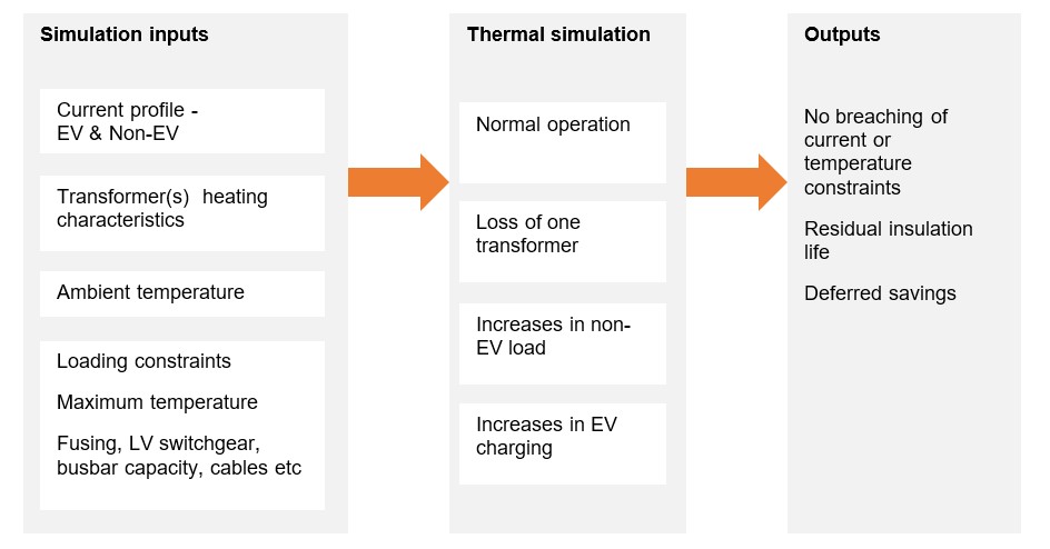
Figure 2 - Model developed for study
3. Whangārei distribution substation
This site supplies commercial and office space in the CBD, and had an EV charger bank connected in December 2020. The daily peak non-EV load is usually between 200 and 300 kVA, shown in Figure 3. Like the rest of New Zealand, Whangārei was in COVID-related lockdown and work-from-home from August onward, explaining the fall in load. Consequently, for this period the load is lower than its normal level, which must be taken into account in any evaluation because it should not be presumed that future spring loads will be similar. Annual peak load occurs in the winter months, where the low ambient temperature will cool the transformers more than during hot days.
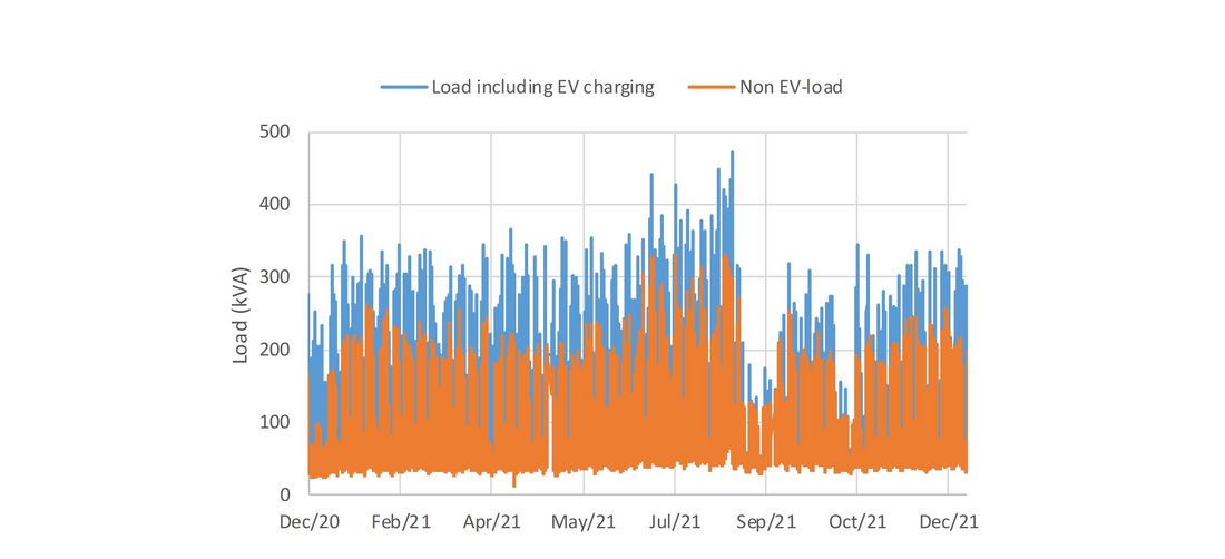
Figure 3 - Load supplied by substation
Two 500 kVA transformers supply the load using a common bus. When a bank of four 120 kW chargers is connected, then there is the potential for an extra 480 kVA of load (assuming unity power factor). With both transformers in operation, the 700 to 800 kVA required by the existing load plus all four charger bays in use will be comfortably met. However, what would happen if one transformer was offline or repurposed? The 700 to 800 kVA is around the normal cyclic rating of a transformer in accordance with IEC 60076/7 guide of 150% rated loading (as long as the transformer is given sufficient time to cool). Thus, thermal modelling was performed on only one transformer being loaded.
Analysing the thermal performance of these transformers will help ascertain whether using a normal cyclic rating, or long-time emergency overload, is a suitable strategy to follow during an N-1 contingency event. This is beneficial if the utility can be assured that there is little impact on the remaining transformer.
Figure 4 below shows the load drawn by the charger bank on one day. As can be seen, the load is very peaked, and a charging cycle is complete within the hour. Given that the thermal time constant of the transformer oil volume is usually around 2 ½ to 3 hours, the temperature of the transformer is not expected to reach a high steady level during this load profile. This will be analysed in the next section using a thermal model.
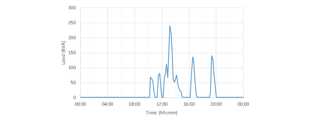
Figure 4 - EV-charging load during a high-use day, 14th August. Peaks are relatively short in comparison with transformer oil thermal coefficient of hours
4. Thermal modelling of transformer
To emphasis the normal cyclic rating of a transformer, thermal modelling was performed with only one transformer connected. Even then, the total load shown in Figure 3 has not exceeded the nameplate rating of one transformer. With a view to the future, for this modelling the EV load was also doubled. Ambient temperature data, essential for the thermal modelling, was downloaded from the local weather station operated by the National Institute of Water and Atmospheric Research.
Figure 5 shows the modelling of transformer winding temperature during a high-use week, which includes the charging load shown in Figure 4. As can be seen, even with the high EV-charging peaks, the transformer temperature only increases slightly because of the high thermal constants. The winding will heat up in accordance with the four-minute thermal constant. However, once the EV charging load falls the winding will be cooled quickly by the surrounding oil. As the thermal constant of the oil is three hours in this study, the oil heats slowly and so will cool the winding effectively. The winding temperature did not exceed 70 °C despite the high load. This is significant because the paper is still ageing slowly, compared to unity ageing at 98 °C where the life of standard Kraft paper is one year [4]. The temperature rise was slowed by the thermal inertia of the insulation.
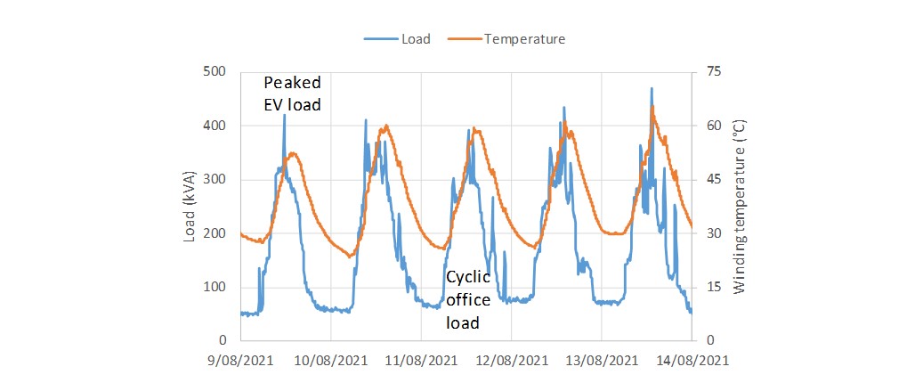
Figure 5 - Thermal modelling of a high-usage week, which data shown in Figure 4 is part of
The EV load was doubled in the simulation and was capped at four charging bays being in use simultaneously. This represents a highest-use scenario for the transformer because its temperature rise is a function of the square of the current, i.e. the power loss will be higher with four bays charging simultaneously rather than one single bay supplying four charges in series.
Even on one transformer, the load is usually under the 150% normal cyclic rating. There was only one 10-minute period when the load was (slightly) higher than this. The high-use week in August is shown in Figure 6 where it can be seen that since the time above 150% load is so short, the temperature does not increase significantly. The winding and oil temperatures are within limits (Figure 7). The importance of the oil temperature is that the radiator bank and top of the transformer will trend towards this.
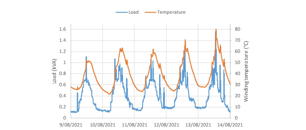
Figure 6 - Winding temperature of high-use week, with doubled EV load
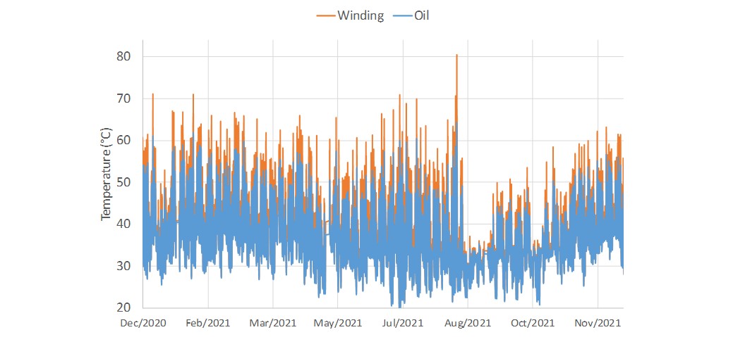
Figure 7 - Oil temperature with doubled EV load. Radiator bank and lid of transformer will rise to this temperature. Winding temperature also shown
The remaining life of the paper insulation was evaluated by the relative ageing rate. As mentioned previously, the life expectancy of normal Kraft insulation paper is one year when heated continuously to 98 °C, in air and 2% water [4]. Thus, a relative ageing rate of 1 indicates a life expectancy of one year (at 98 °C), or a rate of 0.1 showing a life expectancy of ten years. Figure 8 shows the relative ageing rate for the transformer. As can be seen, it has remained low, so the remaining life of the transformer insulation has not been notably affected, and the insulation will still last decades.
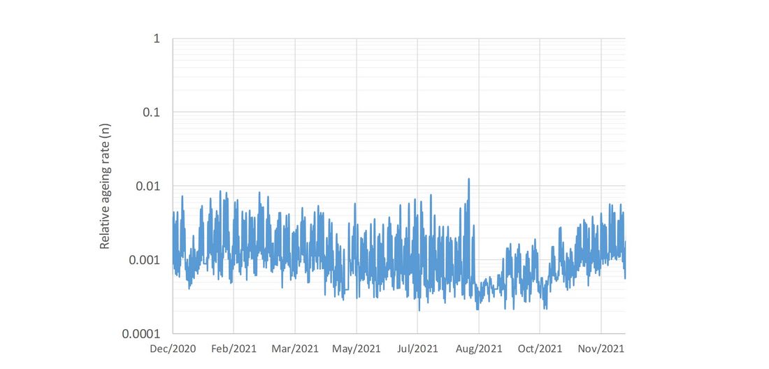
Figure 8 - Relative ageing rate of Kraft insulation paper with EV load doubled
5. Discussion
This analysis has shown that these transformers can be momentarily loaded higher than their nameplate rating. The relatively short duration of an EV charging cycle did not lead to a significant increase in transformer temperature, even when this load was doubled. Thus, it is concluded that a transformer can be better utilized if the LV current is monitored, which benefits the customer and utility in the long run. However, a limitation is that not all transformers are designed to operate at 150% (IEC 60076/7) because of subcomponent ratings. Often, only 120% is provided by a manufacturer to meet design standards. Cooling fans can be considered as an upgrade. However, the transformer may still be limited to 120% overload because of its subcomponents. The suitability of the airflow within the substation must also be verified, and any safety aspects such as public being able to access the fan considered.
Measuring the surface temperature of the tank should also be considered. Although there will be a temperature gradient between both sides of the tank wall, this measurement can be used to ensure that the transformer does not become too hot and check the accuracy of the thermal model.
An options analysis table is shown (Table 2) comparing potential strategies. In general, expenditure into monitoring is likely to be seen as preferable to the immediate upgrade of substation. Collecting data on community charging behaviour will also help the industry understand how to plan networks better.
| Analysis of different strategy | ||
|---|---|---|---|
Strategy | Include EV charger within rated transformer load. | Defer transformer upgrade by using its normal cyclic rating, which permits it to be loaded higher than its nameplate rating. | Upgrade distribution substation for charger connection. |
Methodology | Determine existing load, and then check how much excess capacity is available. May need LV monitoring. Connect a charger if there is spare capacity. | Install monitoring and track the loading profile and temperature of transformer. Use this data to improve utilization. | Decide which charger to install, and then upgrade distribution substation nameplate rating to match charger. |
Pros | Minimal asset upgrade costs. | Defers transformer upgrade, increase in charging is tracked and then a substation upgrade planned once EV numbers increase enough. | Site is ready for mass-usage of EVs.
|
Cons | Limits charger installation only to transformers with sufficient spare capacity available. Limits number of chargers to be connected to a substation. Conservative as does not utilise thermal inertia or ability of transformer to ride through high load. Negative customer perception if there are not enough chargers available. | Other possible electrical or temperature constraints around the site. The rate of EV uptake is uncertain, a utility could be unprepared if there is a fast take-up of EVs. | Inefficient use of capital if the charger is unlikely to be in constant use for possibly several years until EV volumes increase. A larger transformer can require changes to substation to maintain compliance with fire, safety & environmental policies. |
Example costs | ≈NZ$5k for monitoring, installation and data evaluation. | ≈NZ$10-20k for monitoring, installation, data analysis, thermal modelling and interpretation time. | NZ$100-300k for substation upgrade. |
6. Conclusions
The short, peaked, load of an EV charging cycle results in the transformer not heating significantly due its large thermal inertia. However, if the transformer is not given sufficient time to cool between charging cycles then it will continue to heat up.
Consumer charging behaviour around most networks is still fairly unknown. Using monitoring helps a utility build a picture where consumers are likely to charge.
Electronic devices to monitor load are concluded to be effective compared to the traditional planning paradigm of making networks so robust no monitoring is needed.
Acknowledgment
The authors thank Doug Ray, CIGRE NZ Chair, for reviewing this article.
References
- Transpower, Whakamana i Te Mauri Hiko Empowering our Energy Future, New Zealand, 2020.
- Transpower, A Roadmap for Electrification – Decarbonising transport and process heat, New Zealand, 2021.
- IEC 60076-2, “Power transformers - Part 2: Temperature rise for liquid-immersed transformers”, Switzerland, 2011.
- IEC 60076-7, “Power transformers - Part 7: Loading guide for oil-immersed power transformers”, Switzerland, 2018.
- Task Force D1.01.10 , “Ageing of cellulose in mineral-oil insulated transformers,” 2007, CIGRE Brochure No. 323.
- Working Group A2.20, “Moisture equilibrium and moisture migration within transformer insulation systems”, CIGRE, 2008.
- D. Martin, F. Zare, G. Caldwell, and L. McPherson, “Calculating the Residual Life of Insulation in Transformers Connected to Solar Farms and Operated at High Load”, IEEE Electrical Insulation Magazine, Vol. 36, Iss. 6, pp. 10-20, 2020.
- IEC 60076-1, “Power transformers – Part 1: General”, Switzerland, 2011.
- IEC 60137, “Insulated Bushings for Alternating Voltages above 1 kV”, Switzerland, 2008.
- D. Susa, K. B. Liland, L. Lundgaard, and G. Vårdal, “Generator step-up transformer post mortem assessment,” Eur. Trans. Elect. Power, vol. 21, no. 5, pp. 1802–1822, Jul. 2011.
- D. Martin, Y. Cui, C. Ekanayake, H. Ma, and T. Saha, “An Updated Model to Determine the Life Remaining of Transformer Insulation”, IEEE Transactions on Power Delivery, Vol. 30, Iss. 1, pp. 395 – 402, 2015.