Advanced Condition Monitoring of New and Upgraded Turbine Generators for Highly Flexible Grid Demands Using Special Fibre Optic Sensors
Authors
T. BOSSELMANN, S. STRACK - Siemens AG, Germany
J. R. WEIDNER - GenAdvice Consulting, Germany

Summary
The fast-rising amount of renewable energy with volatile electrical power generation results in a need of grid stabilization demands. New highly flexible power stations in combination with upgrading projects of existing units request for improved generator design solutions tailored to these new grid requirements. In parallel the decreasing prizes of electrical energy at the liberalized market leads to cost pressure on the power plant assets of the utilities. This forces manufacturers to develop a new generator portfolio with higher efficiency, excellent reliability at all kind of operation regime, adequate maintenance intervals and much lower lifetime operation costs.
Advanced condition monitoring of the generator main components like stator winding and stator core enable early indication of operational wear or accelerated aging effects due to harsh peak load operation regime. Special designed fibre optic sensers (FOS) can be used at many locations inside the generator, that are not accessible for conventional sensors due to high electric and magnetic field strength. This paper describes the application of different type of FOS used for design validation during prototype tests and applied for permanent online monitoring of the unit at peak load operation on grid demands.
The following fibre optic sensors are examined, most of them use Fibre Brag Grating (FBG) technology:
- Distributed temperature sensor arrays directly applied to the copper conductor of stator winding bars,
- Acceleration (vibration) sensors installed at front-end position of stator winding baskets,
- Strain sensors applied at selected stator bar involutes of highly stressed phase separations,
- Magnetic flux sensors for verification of calculated magnetic field distribution at slot exits and at axial overhang locations.
An example of end-winding vibration monitoring using FOS depicts the usefulness of permanent assessment of generator overhang components to avoid transient overstressing and early defects of winding coils or structure elements. Permanent monitoring of vibration modes and displacement amplitudes ensure good and safe operation condition with well predictable long-term wear.
In a second example the need of stator winding copper temperature monitoring with fibre brag arrays is pointed out, to avoid undiscovered thermal hot spots at the high voltage winding insulation system resulting in sudden defects with high economic impact.
This essential information gathered from sets of FOSs applied at pre-calculated winding locations ensures a reliable long-term operation of the end-windings even under harsh operation conditions. Service experience with fibre optic online monitoring obtained at several machines of new or improved design demonstrate the advantageous use of FOS for condition assessment at highly stressed generators of nowadays.
Keywords
Fibre optic sensors - fibre brag grating technology - online monitoring of operational stress - grid demand - fast load fluctuation - on-site field validation - stator end-winding vibration - operational temperature distribution of copper conductor, high voltage stator winding1. Introduction
The fast-rising amount of renewable energy with volatile electrical power generation results in a reorientation of the electric energy market [1] and a need of grid stabilization demands [2]. New highly flexible power stations in combination with upgrading of existing units with lifetime extension request for improved generator design solutions tailored to these new grid requirements [3]. In parallel the decreasing prizes of electrical energy at the liberalized market leads to cost pressure on the power plant assets of the utilities. This forces manufacturers to develop a new generator portfolio with higher efficiency, excellent reliability at all kind of operation regime, adequate maintenance intervals and much lower lifetime operation costs. For grid stabilization with reactive power demands it includes optimized design for new state-ot-the-art synchronized rotating condensers [4].
A new pressurized air-cooled turbine generator with a direct water-cooled stator winding meets all these requirements. It represents an innovative generator series, which combines proven technologies with new design concepts like load-dependent pressurized air-cooling. This machine type is an excellent solution for flexible high-power applications as well as synchronous condensing applications where additional grid stability is needed. Its key features are presented in separate papers [3], [4].
Advanced condition monitoring of generator main components like stator winding and stator core enable early indication of operational wear or accelerated aging effects due to peak load operation regime. Special designed fibre optic sensers (FOS) can be used at many locations inside the generator, that are not accessible for conventional sensors with copper leads due to high electric and magnetic field strength [5], [6].
2. Types of fiber optic sensors applied AT generator
For design validation during prototype Factory Running Tests (FRT) a large bunch of all kind of sensors was installed at the generator. Table 1 lists all 1230 sensors placed at many specific locations within all parts of the generator to get a maximum of information during each step of prototype running tests. Most of them will stay in the machine for online monitoring at peak load operation in the power plant later on to get first information about real service stress running at the grid.
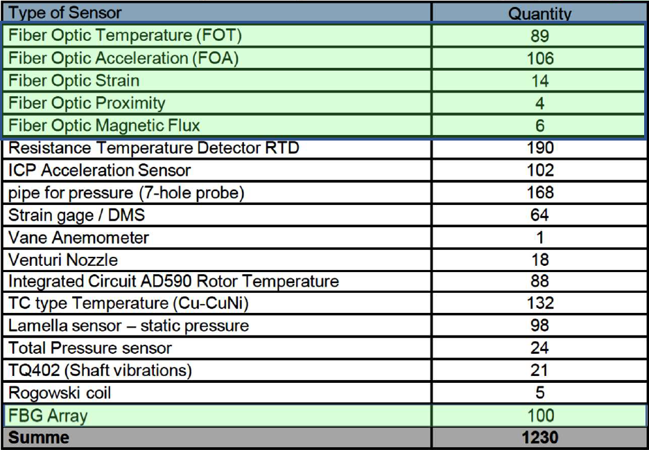
Table 1 - List of different type of sensors installed during prototype running procedure in the generator test field of the factory; Fibre Optic Sensors (FOS) highlighted in green
As can be seen, for FRT more than 300 FOS of different kind had been installed at the generator and remotely online monitored from the test field control room. This includes the following type of fibre optic sensors, most of them use Fibre Brag Grating (FBG) technology.
- Temperature Sensor: -60 … +250°C
- Acceleration (Vibration) Sensors: Resolution ±0,1 m/s², range ±0,5 … 400 m/s²
- Strain Sensors: Sensitivity ±1 μm/m
- Proximity (Displacement) Sensors: Sensitivity ±10 μm/m, dynamic range ±10 mm/m
- Magnetic Flux Sensor: H-field sensitivity 0,1 mT, dynamic range 1 Tesla
- Distributed Temperature Sensor Arrays (FBG) at stator winding bars: -60 … +200°C
To give an overview of the physical mode of operation and technically realisation of the mainly used sensor types, a short description with an application example at a turbine generator is presented in the next chapters.
2.1. FBG temperature sensor arrays
Fibre Optic Temperature (FOT) sensors used at stator windings of large generators are based on FBG principle with up to 12 sensors in series on one fibre only (temperature sensor array), that is placed near the copper conductor to measure the distributed warming-up of the winding direct at the source [7]. In Fig. 1 the application of FOT sensors during stator bar manufacturing process is shown. It can be seen, that the FBG sensors are placed directly at the narrow side of the pressed copper conductor bar before starting the taping process for applying the HV main insulation.
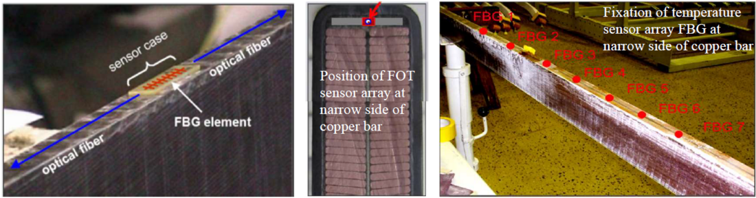
Figure 1 - Array of fibre optic temperature sensors applied at narrow side of copper conductor Roebel
bar before starting of HV insulation taping
Application details together with temperature measuring results gained at a complete generator stator winding are described in chapter 4, see below.
2.2. Accelerator sensor
In order to be able to measure end-winding vibration behaviour of high voltage stator end-windings at high potential and high magnetic flux levels a novel fibre optic accelerometer has been developed. The working principle is based on intensity modulation of light using a simple configuration of a bare multimode fibre that is placed towards a tilted mirror [8]. A defined length of the fibre sticks out at the end of the ferrule like a cantilever bar, as shown in Fig. 2. When the sensor head is accelerated the fibre is bended due to its own inertial force. This changes the distance of the fibre end to the mirror and therefore the amount of light back reflected into the fibre. The design avoids relatively moving parts and therefore leads to a very tough and small sensor housings. Because of a passive operating sensor concept using a low power LED, the accelerometer can be used in an explosion protected area without further precautions like hydrogen cooled generators or HV motors at chemical industry and off-shore platforms.
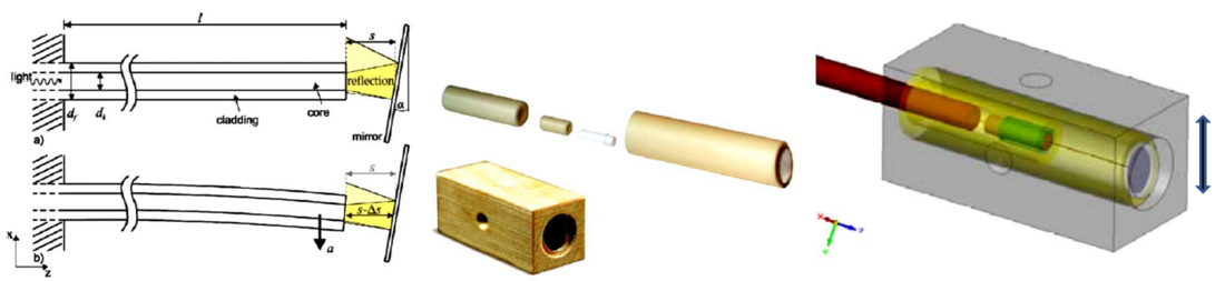
Figure 2 - Working principle of cantilever type fibre optical accelerometer based on intensity modulation of light reflected at a mirror and vibration sensor produced with non-metallic elements made of insulation material
Some typical examples for a design dependent installation of Fibre Optic Acceleration (FOA) sensors at front-end stator overhang locations are presented in Fig. 3.
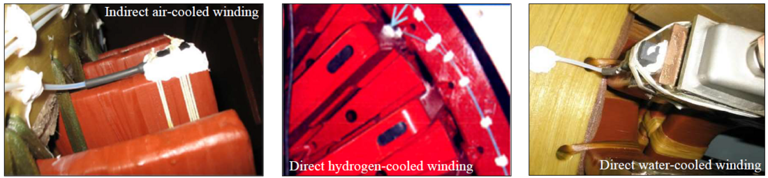
Figure 3 - Examples of FOA sensor locations at different type of stator end-winding design depending on generator power and cooling category
2.3. FBG strain sensor
The fibre optic strain sensor is suitable for monitoring dynamic strain at stator winding bars and endwinding structure elements inside large hydro or turbine generators. The sensor – an example is shown in Fig. 4 – consists of insulating materials only and it is completely passive. This makes it ideal for areas where conventional electrical strain gauges are not useable. Therefore, it is preferably used at locations, that are exposed to electrically high potential, high magnetic fields, severe electromagnetic interferences and explosive gas atmospheres. It can be placed on top of a high voltage stator winding bar as presented in Fig. 4. It is also applied at highly dynamic-mechanical stressed support elements of end-windings.
Since dynamic strain measurements do not need to be compensated for slow ambient temperature drifts, the sensor consists of a single FBG only. Light from a broadband light source is reflected at the FBG structures. Depending on dynamic strain variation and quasi-static temperature behaviour, the spectral signal changes that can be measured with a spectrometer. The sensor signals are composed of a slowly varying direct part (coming from static strain and temperature) and a fast-alternating dynamic part (coming from dynamic strain) that can be easily distinguished.
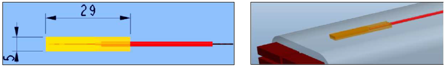
Figure 4 - Fibre optic dynamic strain sensor with application examples at top of a stator winding bar
The mechanical overstressing of a stator bar high voltage insulation system, that is mainly caused by high dynamic-mechanical transients or thermo-mechanical stresses due to overload conditions could lead to accelerated fatigue. Therefore, it is recommended for specific applications of hydro or turbine generators that the strain should be measured in addition to the vibration behaviour of the winding overhang.
Permanent installation of strain sensors had been performed at two top layer winding bars of different electrical phase in the slot exit region of an indirect cooled generator, see Fig. 5. Four FBG strain sensors were applied at each bar at different axial locations (blue arrows in Fig. 5 ) to measure the dynamic mechanical tension of the insulation in this highly stressed part of the overhang.
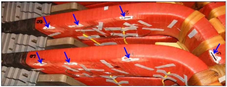
Figure 5 - Tiny FBG strain sensors (small black strips marked with blue arrows) fixed with white glue and adhesive tape strips on the surface of stator winding insulation at end-winding involute – two top bars at phase separation
2.4. Magnetic flux sensor
During prototype tests of new designed and more efficient generator components like stator bars or advanced core end shape the measurement of local magnetic field distribution is essential for verification of used calculation programs. Magnetic flux sensors that could be applied at locations with high electric potential and electromagnetic interference would be the best option for these test field runs. Magnetic field sensors basing on the Faraday effect had been developed. The realized design for practical application is presented in Fig. 6. Linear polarized light is guided through the Faraday crystal while it rotates the polarization vector. The modified light is then converted into an intensity modulation by a second polarizer which is oriented an angle of typically 45° to the input polarization. Light intensity modulation correlates to magnetic flux variation and can easily be measured with optical equipment.
As shown in Fig. 6 (b) and (c) the sensor body is made of ceramic, glass prisms, Faraday crystal, optical polarizers of glass and high temperature resistant plastics, which makes it completely dielectric.
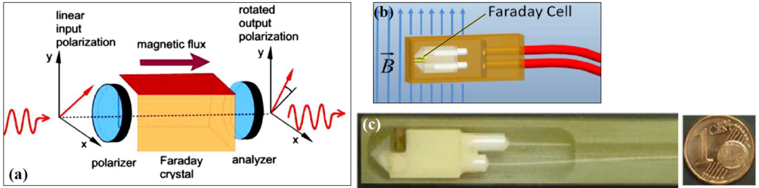
Figure 6 - Principle of magnetic flux sensor with a Faraday crystal (a) and practically realized fibre optic sensor (c) as small as a 1cent coin
The new fibre optic magnetic flux sensors were implemented at stator winding overhang of turbine and hydro generators [9] to measure the magnetic field distribution at axial locations between stepped core and front-end bar connections as shown in Fig. 7. Because these flux sensors are made of non-metallic material, the applied sensor and connection line could easily be positioned all over the end-winding construction without taking into consideration any obstruction of high electric or magnetic field distribution as demonstrated in given image sections of Fig. 7.
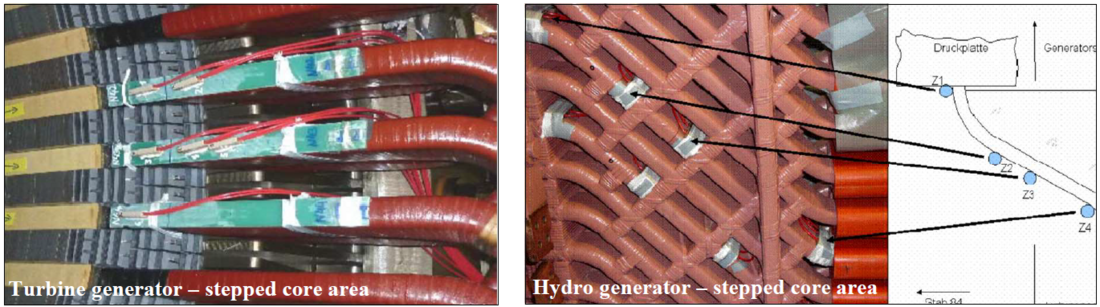
Figure 7 - Application of magnetic flux sensors at stator winding exit in stepped core area of an indirect cooled generator
3. Example 1 - Stator endwinding vibration monitoring with fiber optic acceleration sensors
During load operation the generator stator windings will be excited by the following three major sources of force:
- Bearing and shaft vibration acting at the 1st grid harmonic (e.g. 50 Hz) for 2-pole generators,
- Magnetic forces of rotating flux field in stator core also called “core ovalization” forces acting at the 2nd grid harmonic (e.g. 100 Hz) and
- Electromagnetic forces generated by stator current in the winding with grid frequency. The stator current generates forces with double grid frequency (e.g. 50 Hz) resulting in a vibration frequency of the 2nd grid harmonic (e.g. 100 Hz) and higher harmonics.
Fibre optic accelerometers can easily measure the vibrational behaviour and dynamic-mechanical stress of stator end-windings operating at high potential well above 10 kV and even higher. Different type of sensors are commercially available on the market and several application papers are presented so far [10], [11]. With this important information it is expected to get better knowledge on stress dependent changes in the end winding structure and to ensures a reliable long-term operation even in harsh peakload condition. The following example gives an impression of online end-winding vibration monitoring
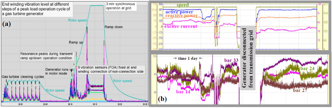
Figure 8 - Monitoring of stator end-winding behavior during different generator load conditions at volatile grids (a) End-winding vibration level at start-up and shut-down process of a gas turbine generator in peak load cycle (b) Displacement of four selected stator bar front-end locations (top to bottom bar connections) in correlation to generator power condition
Permanent online monitoring of end-winding vibration behaviour as depicted in Fig. 8(a) ensures avoiding overstressing of overhang structure during extreme peak-load demand at volatile grids due to high content of renewable energy feed-in. The influence of peak-load cycle on end-winding vibration level as given in Fig. 8(a) can be pointed out as follows:
- Different rotor speed dependent low level vibration resonance peaks at rotor speed of ~ 700 rpm during typical gas turbine leaning cycles before starting the ramp up of a gas turbine with the generator running in motor mode,
- Some normal end winding resonance peaks during transient ramp up of the rotor to full speed before synchronization to grid,
- Low vibration level of end-windings at synchronous load operation of the generator as expected by design requirements,
- During fast ramp down only one load rejection resonance peak because of transient winding current at the moment of disconnection from grid,
- No thermal equilibrium of stator end-winding reached and therefore no thermo-mechanical influences on winding basket resonance behavior measurable.
The second example of online vibration monitoring at field condition is presented in Fig 8(b). It demonstrates the distinctive influence of active and reactive power variation on the end-winding displacement amplitudes (0-pk) at the stator bar front-end connections, see trend diagram of a few days as shown in Fig 8(b). As there is not a strong and direct correlation between power and bar displacement the delaying influence of temperature and thermo-mechanical stresses has to be taken into consideration.
This example clearly illustrates the sophisticated dynamic-mechanical behaviour of the overhang structure of a high voltage stator winding. Fibre optic vibration sensors together with other non-metallic sensors are indispensable measuring tools for design validation tests at stator end-windings to produce a reliable and robust overhang basket. For more details about end-winding vibration measurement with FBG sensors and for interpretation of test results the following literature could give further and deeper information [8], [12] - [14].
4. Example 2 - Stator winding temperature monitoring
To get information about the thermal behaviour of generator stator windings and possible design warm spots at stator bars in the overhang or slot section FBG sensor arrays could be implemented for direct temperature measurement of copper conductors that operate at high voltage [15]. At an indirect aircooled generator many FBG temperature sensors have been installed at selected locations along the slot and involute part of a stator winding bar is shown by the green marker points in Figure 9.
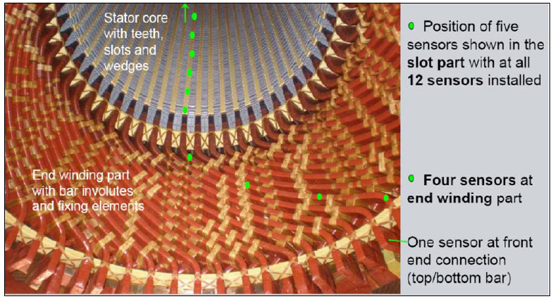
Figure 9 - Bottom half of an indirect cooled generator stator with marked positions of FBG sensors measuring axial distribution of copper conductor temperature
4.1. Stator end-winding area
During the prototype Factory Running Tests (FRT) of a new generator the copper temperature distribution of a stator end-winding area has been monitored. Therefore, five FBG sensors were applied at selected top and bottom bars each, to measure the axial distribution of the copper conductor temperature between the lead end and the core end at the winding overhang. In Figure 10 the axial temperature distribution of three top bars and two bottom bars is displayed.
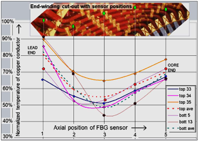
Figure 10 - Copper temperature distribution of selected top and bottom bars at stator end-winding area between lead end and core end during test field run – indirect air-cooled generator
The following valuable information can be collected from the given temperature readings:
- The highest copper temperature is measured at the top-to-bottom bar brazing connection at the lead ends because of eddy currents warming up at copper pieces. Nevertheless temperature is far below thermal class temperature of the insulation system.
- The lowest temperature is – as expected from design calculation – in the radially well cooled middlepart of the end-winding area.
- The temperature increase towards core end accrues due to higher magnetic fields close to stepped stator core end.
- The average temperature of bottom bars is lower than the one of top bars because of cold air flow direction.
- The measured copper temperature distribution at stator bar envolutes enables an excellent crosscheck with obtained results of sophisticated generator calculation programs.
4.2. Stator winding slot part
The temperature distribution within the stator winding slot part, measured during the test field run of an indirect air-cooled generator is given in Figure 11. The sensitive temperature readings of FBG arrays at the different cooling zones (radial cold and warm air flow) give excellent data for validating the used thermal calculation program [16]. Due to the symmetric cooling zone design of the stator core with axial blower at drive and non-drive end, the temperature distribution is only measured at one side up to the center of the stator core, see Fig. 11.
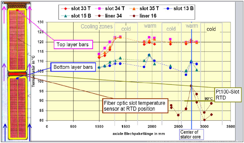
Figure 11 - Axially measured copper conductor temperature distribution at top and bottom layer bars compared with conventional slot RTD reading during test field run
The following conclusions can be drawn from the temperature distribution at winding copper conductors presented in Fig. 11:
- The copper conductor temperature at top layer bars is significantly higher than at bottom layer bars because of higher eddy current losses at top bars generated by greater magnetic flux density at upper part of the core slots.
- The influence of radial cooling zones between warm and cold air sections is only significant at bottom layer bars. At top layer bars the cooling air flow is too much influenced by mixed air gap flow.
- The fibre optic slot temperature sensors (brown dots in Fig. 11) located near conventional RTD sensor position reproduce the difference between warm and cold cooling air zones in an excellent way. But because these temperature sensors are placed on top of insulated copper bars the measured temperature is about 7 K lower than the warm spot temperature measured with FBG arrays directly at copper conductor surface without high voltage insulation in between.
- The temperature reading of conventional slot RTD sensor installed according to IEC Specification is about 30 K lower than the measured copper conductor hot spot temperature of the stator winding. Nevertheless, the thermal class temperature of the insulation system of 155°C is far away to be touched. Also, the utilization temperature of the stator winding insulation of 130°C is not reached.
Summarized results:
The FBG temperature arrays installed directly at the copper conductor surface produce an excellent thermal image of the local temperature distribution inside the stator winding during generator operation. After some years of in field operation at different type of generators no sensor defects due to broken fibre or even sensor related temperature drift has been observed on any installed FBG sensor. During a planned maintenance stand still the sensor readings were checked. After waiting some time for cooling down, the reading from the FBG sensor were compared with the conventional slot RTD and the cooling air thermometer. All values of comparable locations within the cooled down generator stator do agree within a margin of ±1°C, which is accurate enough for monitoring purposes.
5. Conclusions
A severe peak load operation regime of rotating machines due to volatile grid demands results in accelerated wear of components and enhanced aging of the stator winding insulation with increasing risk of unexpected sudden break-down. Therefore, the exact knowledge of stator winding behaviour as one of the most stressed parts of the generator is essential for long-term prediction of a new designed machine. Extensive prototype Factory Running Tests (FRT) need to be performed [17].
It has been shown in the paper, that the use of different kind of fibre optic sensors can essentially help to achieve a realistic picture of stator winding stressing. The advantage of fibre optic sensors (FOS) is that they can be placed at all critical winding locations because they do not have any metallic and magnetic parts and therefore do not influence the high electrical and magnetic fields at generator stator.
A short description of different type of FOS including a sample application has been given for the following Fibre Bragg Grating (FBG) sensors:
- Distributed temperature sensor arrays directly applied to the copper conductor of stator winding bars,
- Acceleration (vibration) sensors installed at front-end position of stator winding baskets,
- Strain sensors applied at selected stator bar involutes of phase separation,
- Magnetic flux sensor for verification of calculated magnetic field distribution at slot exits and axial overhang locations.
A more detailed example of end-winding vibration monitoring using FOS demonstrates the usefulness of permanent assessment of generator overhang components to avoid transient overstressing and early defects of winding coils or structure elements. Field operation experience shows, that permanent monitoring of vibration modes and displacement amplitudes ensure a good and safe operation condition and predictable long-term wear.
In a second example the need of stator winding copper temperature monitoring with fibre bragg arrays is demonstrated, to avoid undiscovered thermal hot spots in the high voltage winding insulation system resulting in sudden defects with high economic impact. This essential information gathered from sets of FOSs applied at calculated winding locations ensures a reliable long-term operation of the end-windings even in harsh operation condition.
The service experience with fibre optic online monitoring obtained at several machines of new design demonstrate the advantageous use of FOS for condition assessment at highly stressed generators of nowadays.
References
- Hans-Werner Sinn: Buffering volatility: A study on the limits of Germany’s energy revolution, European Economic Review, Volume 99, October 2017, pp. 130 – 150
- ENTSO-E Completing the map – Power system needs in 2030 and 2040 – Status November 2020 · Version for public consultation, ENTSO-E, Rue de Spa 8, 1000 Brussels, Belgium
- Hendrik Steins: Design validation, operational data assessment and new maintenance concepts - using the example of the new air pressurized SGen-2000P technology, 14. Essener Tagung - Generatoren in konventionellen Kraftwerken, Windparks und Wasserkraftwerken, HdT, February 2020, Essen, Germany
- M. Baca, K. Walli, A. Joswig: Proper design and configuration of synchronous grid stabilizers to cover the wide variety of requirements, IEEE PES General Meeting, August 2018, Portland, Oregon, USA
- T. Bosselmann, M. Willsch: Optical Sensors for Harsh Environments – Product Portfolio – Sensors for Power Generators & Gas Turbines, Corporate Technology - Siemens AG, 2017
- Thomas Bosselmann: Innovative applications of fibre-optic sensors in energy and transportation, 17th Optical Fibre Sensor Conference OFS, Bruges, 23. – 27.05.2005
- J. R. Weidner: Direct Measurement of Copper Conductor Temperature at Generator Windings with Fibre Bragg Grating Sensors, SC A1 Rotating Machines, Contribution PS1/Q1.6, Cigre 2012, Paris, France
- L. Hübner, T. Bosselmann, A. Jungiewicz, G. B. Gabrielsen, E. Feilkas, K. Dybvik, H. Daum, M. Villnow: Monitoring of winding overhang vibrations on large synchronous motors, Petroleum and Chemical Industry Conference Europe, Amsterdam, 6.6.2014
- M. Villnow, M. Willsch, T. Bosselmann, B. Schmauss, T.Hildinger, T. Hess: Distributed magnetic field measurement on stator winding heads of a 300 MVA water turbine motor-generator using fiber-optical magnetic field sensors, Proc. IEEE Sensors, Nueremberg, 2010
- Tetreault, A.: On-line End Winding Vibration Measurement Using Fiber Optic Sensor Technology, EPRI Major Component Reliability (MCR) European Workshop, Barcelona, April 12th – 14th, 2011
- P. Kung, L. Wang, M. I. Comanici: Stator End Winding Vibration and Temperature Rise Monitoring, 2011 Electrical Insulation Conference, Annapolis, Maryland, 5 - 8 June 2011
- C. Kreischer, H. Steins, S. Strack, J. R. Weidner: New Diagnostic Procedure for Monitoring of Stator End Winding Vibration at Generators with Rapid Load Demand Fluctuation, Cigre SC A1 Meeting and Colloquium, Madrid 2015, Spain
- André Tétreault: On-line End Winding Vibration Measurement Using Fiber Optic Sensor Technology, EPRI Conference, Barcelona 2011, Spain
- J. Letal, B. Satmoko, N. Manik, G. Stone: Stator end-winding vibration in two-pole Machines, Petroleum and Chemical Industry Conference, Cincinnati 2018, USA
- T. Tanaka, H. Murayama, K. Hattori, K. Takahashi, “Direct measurement of strand temperature of turbogenerator with FBG sensors” Paper A1-109, Cigre 2012, Paris, France
- N. M. Theune, M. Kaufmann, J. Kaiser, M. Willsch, T. Bosselmann, P. Krämmer: Fiber Bragg Gratings for the Measurement of Direct Copper Temperature of Stator Coil and Bushing Inside Large Electrical Generators, International Conference on Optical Fiber Sensors 14th OFS, Venice, 11. - 13. Oct. 2000, Italy
- T. Bosselmann, E. Abromitis, V. Chernogorski, S. Lindholm, R. Roeding, U. Schwanengel, S. Strack, M. Villnow, J. R. Weidner, M. Willsch: Design validation of an air-cooled turbo generator by using fibre optic sensors in a shop test, SPIE Defense, Security, and Sensing, Fiber Optic Sensors and Applications IX, Baltimore, 26.04.2012, USA