Case study of dc-MMC interconnecting two HVDC lines with different grid topologies
Authors
D. GOMEZ A. - SuperGrid Institute & Universitat Politècnica de Catalunya
K. SHINODA, J.D. PAEZ, F. MOREL, P. DWORAKOWSKI - SuperGrid Institute
M. CHEAH-MANE, O. GOMIS-BELLMUNT - Universitat Politècnica de Catalunya

Summary
Dc-dc converters for high voltage direct current (HVDC) applications are interesting devices for the development of multi-terminal and dc grid schemes. They can adapt the differences between the dc systems (voltage level, technology and/or line topology) and provide additional protection, controllability and redundancy services. This paper presents a case study of a non-isolated dc-dc converter interconnecting the NordLink and Cobra cable projects. This interconnection requires a dc-dc converter to adapt the dc voltage and the line topology (the first project being a ±525 kV rigid bipole while the second is a ±320 kV symmetric monopole). The case study has been modelled in Matlab/Simulink and several scenarios are simulated. A first set of 8 simulations change the power flow directions verifying the adequate behavior of the dc-dc converter and HVDC links. Based on the previous simulations, additional 16 cases are simulated to verify the system behavior during faults. Two faults are proposed: a pole-to-ground on the positive pole of the rigid bipole line and another on the positive pole of the monopole. It is shown that the dc-dc converter can interconnect two existing lines without changing their initial control strategy. For the normal operation simulations, a fast power variation through the dc-dc converter is tested proving that the line protections are not triggered. The power perturbations created by the dc-dc converter are small enough to keep the system under normal operation conditions. During the fault simulations, the dc-dc converter is able to isolate the healthy side from the fault disturbance (firewall capability). The healthy dc side observes a power disturbance (loss of power flow through the dc-dc converter) without triggering the protections, allowing the continuous power transmission and regaining steady state conditions. The dc-dc converter employs full bridge submodules to be able to block the fault currents, without the presence of dc circuit breakers.
Keywords
dc-dc HVDC converters - dc-MMC - grid topologies - multi-terminal dc grid - modular multilevel converters1. Introduction
High voltage direct current (HVDC) transmission lines are currently used to transmit high power over long distances. The interest in interconnecting two or more HVDC lines has risen in the latest years inspiring multiple publications and a CIGRE working group (B4.76) dedicated to the study of dc-dc converters for HVDC applications.
HVDC transmission system does not have an established standard yet, hence, the installation features vary from one project to another, such as the operation voltage, the technology (line commutated converter or voltage source converter), the line topology (e.g. bipole, monopole), the grounding strategy (e.g. start point reactor), the protection scheme or the conductor type used (cable or overhead lines). Dc-dc converters are important devices for the development of future dc grids [1] as they provide the interface needed to interconnect HVDC systems with different characteristics. Several HVDC dc-dc converters have been proposed in the literature to interconnect two dc systems [2], but the literature focuses mainly on the interconnections between two dc systems with different voltage levels [3], while the impact of their grid topology is not often considered.
There are four different grid topologies for HVDC transmission systems: asymmetric monopole (Fig. 1a), symmetric monopole (Fig. 1b), bipole (Fig. 1c) and rigid bipole (Fig. 1d) [4]. Each topology behaves differently in case of a fault. There are different possible faults: faults pole-to-ground, pole-to-pole, or internal faults in a converter. Both monopoles and the rigid bipole must stop the power transmission during any fault and they remain inoperative until the fault is cleared. Compared to the monopoles, the rigid bipole can be reconfigured to isolate a fault on a converter. Then it can use the healthy conductors and converters to exchange, up to, half of the rated power. However, the rigid bipole loses the complete power exchange capacity in case of a fault in a conductor. In case of a pole-to-ground fault, the symmetric monopole and the rigid bipole have a pole displacement leading to an increased voltage (pole-to-ground) on the healthy pole. The symmetric monopole can experience voltages up to 2 p.u., whereas, voltages around 1.4 p.u. have been reported for a given rigid bipole application [5]. The main advantage of the bipole is its inherent redundancy. Contrary to the rigid bipole, the bipole continues the power transmission, without interruption, for any fault except the pole-to-pole fault. The bipole use the healthy pole and the metallic/ground return to exchange up to half the rated power without being subject to voltage or currents disturbances.
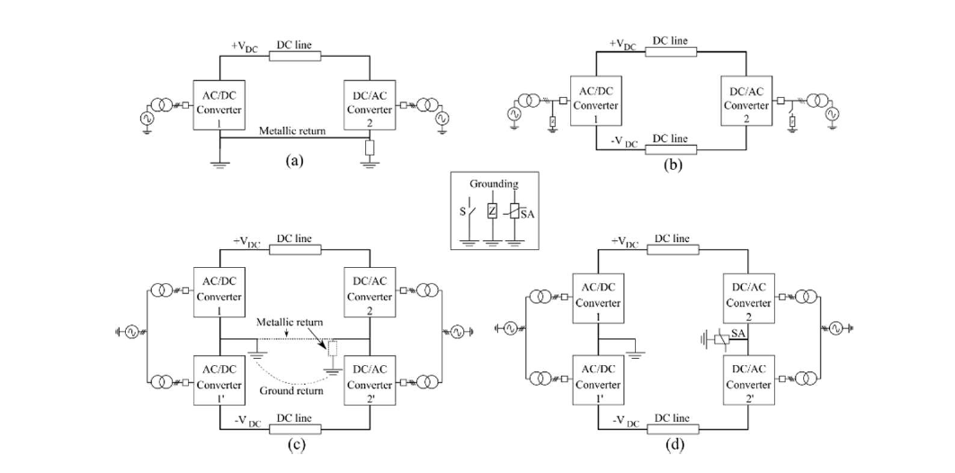
Figure 1 - HVDC grid topologies. (a) asymmetric monopole (b) symmetric monopole (SyM) (c)bipole with metallic or ground return and (d) rigid bipole (RB)
To interconnect two dc systems with different grid topologies, a dc-dc converter is needed. The dc-dc converter must respect the operation limits of each system throughout any operation condition, including faults. These operation limits can vary depending on the installed equipment, the protection strategy and the fault detection algorithm. This paper focuses on the operation limits given by a basic fault detection algorithm. The interconnection of two dc systems with different grid topologies (rigid bipole and symmetric monopole) is considered in this paper. To interconnect the lines, a non-isolated dc-dc converter is considered, here called flexible dc-MMC. The converter is based on the one presented in [6], [7]. It offers lower losses and cost compared to the isolated dc-dc converter front-to-front [8], [9]. The study evaluates the dc-dc converter behavior and its impact on the HVDC systems in normal operation and during faults.
The paper starts by presenting the main characteristics of the HVDC lines to interconnect. Section 3 presents the topology and control of power converters (ac-dc and dc-dc). Section 4 presents the parameters of the simulation model. The simulation results are shown in section 5 and the conclusions are given in section 6.
2. Proposed case study
This paper investigates the use of a dc-dc converter interconnecting two lines with different grid topologies based on a possible case proposed in [4]: the interconnection between the NordLink and Cobra Cable projects. The NordLink project has 54 km of underground cable and 516 km of submarine cable connecting Norway and Germany. This HVDC link is based on a rigid bipole (RB) rated at 1400 MW with ±525 kV [10]. The Cobra Cable project has 325 km of submarine cable interconnecting Denmark and the Netherlands. This HVDC link is based on a symmetric monopole (SyM) rated at 700 MW with ±320 kV [11]. The approximated geographical layout is presented in Fig. 2. The interconnection demands a dc-dc converter able to adjust the dc voltage and the grid topology between the two projects.
The possible benefit of this interconnection is the increased power flow flexibility between all the interconnected countries: Netherlands, Germany, Denmark and Norway. The installation of a dc-dc converter enables the direct power exchange between Norway and Netherlands, not possible in the initial system. The dc-dc converter can also increase the redundancy of the interconnection. After a line or converter fault, the interconnected system can reconfigure itself to isolate the damaged segment allowing the power exchange between the healthy sections. For example, in case of a fault between the dc/dc converter and Denmark (or in the ac/dc converter in Denmark), a power exchange with Netherlands-Norway-Germany could be possible after the fault isolation. In the initial system, the same fault will isolate the Netherlands from the Norway.
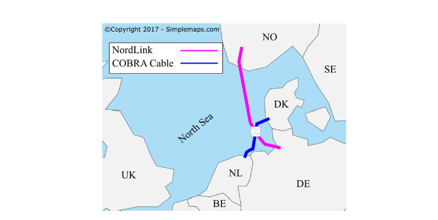
Figure 2 - Map of the North Sea region presenting NordLink and Cobra cable. The dc-dc converter is proposed at the crossing point
3. Converter topologies and control
The proposed case study considers two types of HVDC converters: ac-dc and dc-dc converters. The considered ac-dc converters are modular multilevel converters (MMC). The dc-dc converter is a variation of the dc-MMC presented in [6]. Some details are presented in this section.
3.1. Ac-dc modular multilevel converter
The MMC is shown in Fig. 3, it has two arms per phase (upper and lower). Each arm is composed of a series connection of half bridge submodules (HBSMs) and an inductor. At the connection point between the upper and lower arm, there is an ac output port. The converters used here have 3 legs for a three-phase connection to the ac grid.
The MMC controller is designed in line with [12]. A general control diagram is presented in Fig. 4a. Three energy controllers (total, horizontal and vertical) manage the energy by setting the current references (Iref diff and Iref ac), which are a linear combination of the upper and lower arm currents Iup and Ilow. The control changes the ac current reference depending on the control mode, either voltage control or power control. The voltage controllers were tuned to have a second order response with a time constant of 100 ms and an overshoot of 10%. The converter control adopts a virtual capacitor controller (VCC) as presented in [12], which is a proportional control that helps
to support the dc voltage variations using the energy in the converters: energy stored in the SMs capacitors. The energy in the converter varies proportionally to the dc voltage fluctuation and the virtual capacitor coefficient value, here set to 1. This coefficient is used to calculate the voltage and energy controllers.
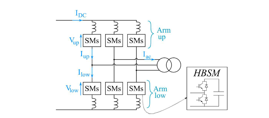
Figure 3 - Circuit diagram of the ac-dc modular multilevel converter: submodule (SM), arm inductor (L) and half bridge submodules (HBSM)
The power control in the rigid bipole is modified (Fig. 4b): both MMCs (positive and negative pole) control the total energy with the ac current and have a common dc terminal voltage ΔVdc to control the dc power [13]. The station controlling the voltage implements the control presented in Fig. 4a including VCC.
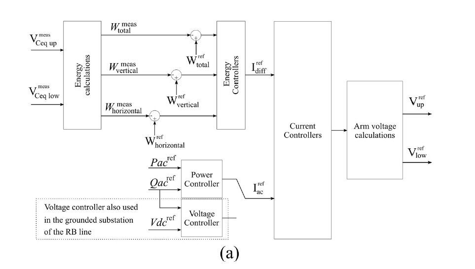
Figure 4 - MMC control diagrams (a) The general control strategy for power or voltage control mode
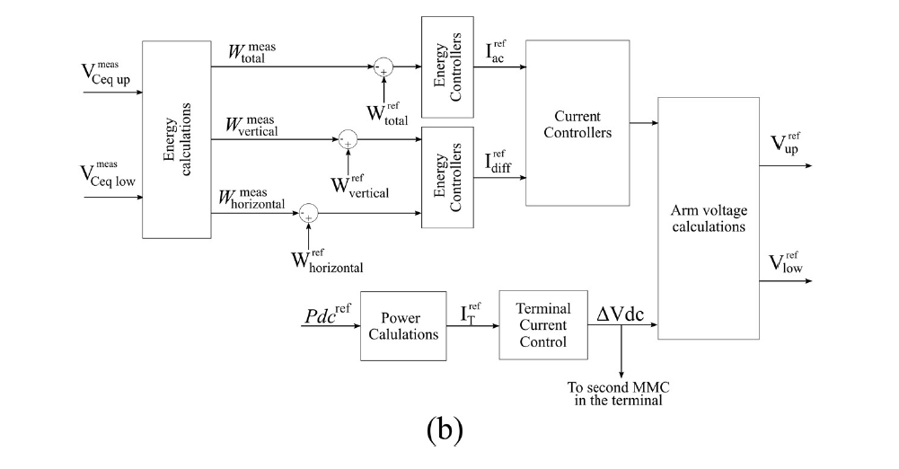
Figure 4 - MMC control diagrams (b) The terminal control for the rigid bipole (ungrounded station)
3.2. Flexible dc-dc modular multilevel converter
The dc-dc converter used for the proposed case study is a modular structure presented in Fig. 5. Each phase of the converter is composed of 3 arms (upper, middle and lower). These arms contain a series connection of submodules (SMs) either half bridge (HBSM) or full bridge (FBSM) and an arm inductor (L). The FBSMs are used to have negative voltage outputs and to block the dc fault currents. The dc-dc converter needs enough FBSMs to block the fault interactions between the two interconnected dc systems. In this study, the upper and lower arms use 400 FBSMs each. The converter has an output passive filter (Lout) allowing the ac power to circulate between phases and other arms. These interactions are needed to keep the internal energy balanced [7], [14]. Although Lout works as an ac filter, the control strategy keeps the phase currents balanced to avoid ac components on the dc side. The high voltage side (left side in Fig. 5) is connected to the rigid bipole while the low voltage side (right side in Fig. 5) is connected to the symmetric monopole line. The number of phases can change depending on the converter rated power and the semiconductors current rating. A dc-dc converter with three phases is considered in this paper.
The converter is controlled to keep the internal energy constant, while a power is transferred between dc systems. The control strategy is a cascaded structure with the high level control following the energy references and the low level controlling the currents. There are three energy controllers per converter phase: total energy (Σ), total difference (ΔT) and the difference between the upper and lower arm (Δu-l). The internal currents are controlled to follow the references given by the energy controllers, the pole imbalance (on the monopole side) and the power reference, as shown in Fig. 6. In this work, a power control mode is implemented, but additional controllers can be added to control the voltage on the dc sides.
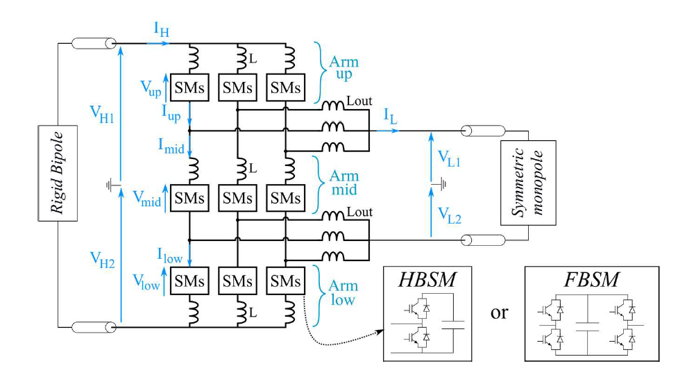
Figure 5 - Flexible dc-MMC for interconnections between different grid topologies
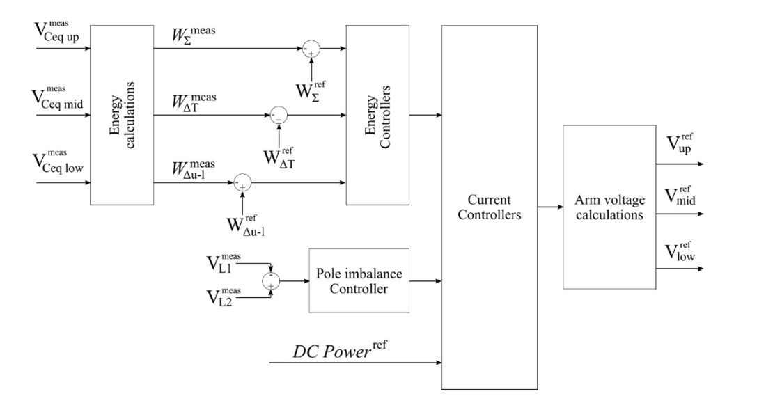
Figure 6 - Control strategy used for the dc-dc converter
4. Simulation model
Figure 7 shows the schematic of the simulation model implemented in Matlab/Simulink. The 7 converters were implemented using the parameters presented in Table 1. The converters use average arm models, including the blocked state, depending if they are composed by HBSM [15] or FBSM [16]. The cables are modelled using the wideband model from the Best Paths project [17]. The model considers two reference points: the first on the dc side of the RB, which is grounded through a resistance (RG) of 0.7 Ω as presented in [5]; the second, on the ac side of the SyM line through a star point reactor as shown in Fig. 7 [18, p. 291].
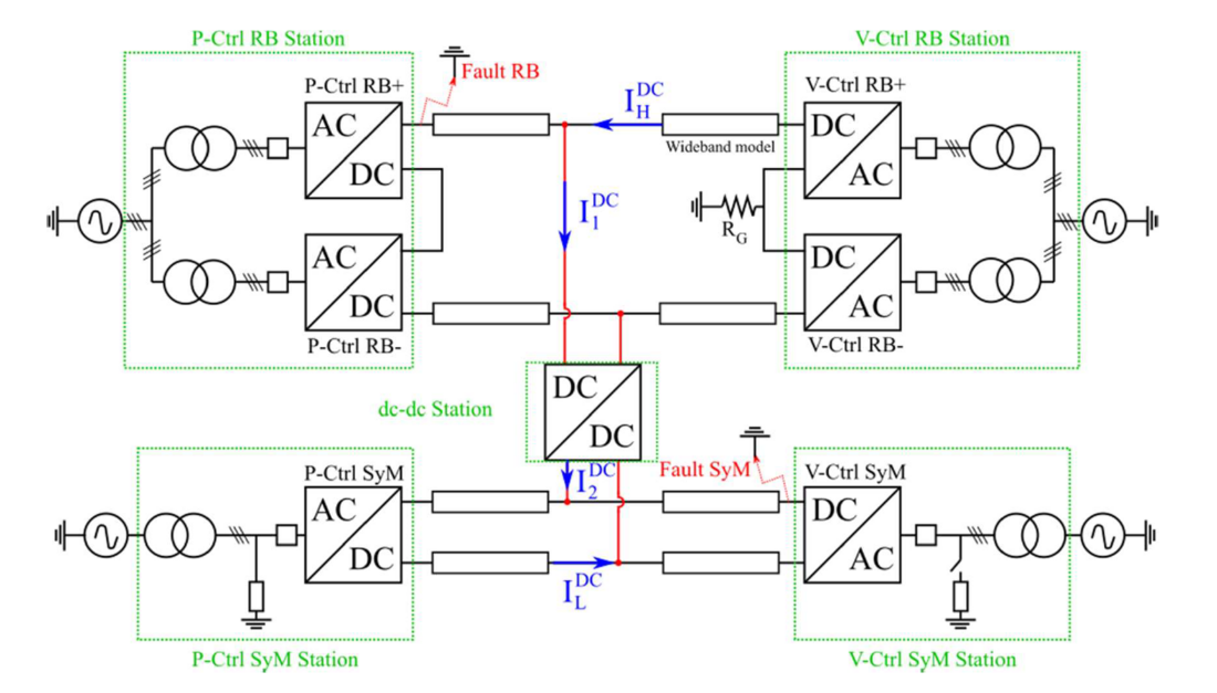
Figure 7- Proposed case study interconnecting a rigid bipole (upper side) with a symmetric monopole (lower side). The currents present the positive power flow direction in the lines and through the dc-dc converter. The squares adjacent to each ac-dc converter represent the ac circuit breakers
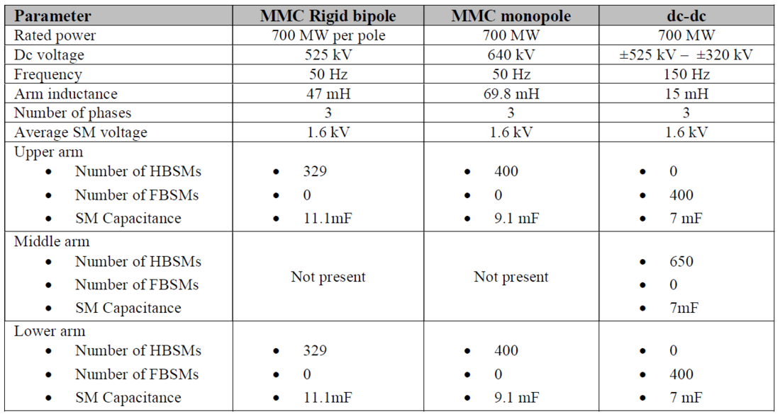
Table 1 - Converters parameters
The five converter stations implement a fault detection algorithm, which uses local voltage and current measurements to detect a fault. The fault detection algorithm blocks the converter before the arm current reaches 3 kA, as the complete case study was designed using IGBT valves rated at 1.5 kA and 3 kV. After blocking the converter, it is assumed that the fault current circulates through the by-pass thyristors integrated within the SMs [18]. In addition, the algorithm trips the station ac circuit breakers (ACCB) to stop the fault current contribution from the ac side. The fault detection algorithm has a 300μs delay [19] to emulate the detection, communication and tripping time inside a converter station. An additional 100ms delay is added to the ACCB opening signal. With regard to the voltage measurements, the algorithm triggers the block signal if the measurements deviate 20% from their nominal values. The voltage thresholds in the dc-dc converter are set to 15% of deviation, to block the converter before the tripping of the protections in the lines. This last feature allows the dc-dc converter to act as a firewall i.e. preventing the spreading of fault disturbances from one side to the other.
5. Simulation results
The proposed case study interconnecting two HVDC lines using a dc-dc converter may have multiple power flow distributions around the system. Figure 7 shows the positive convention for the dc currents, which are also used for the power direction. The positive power direction in the lines are from the dc side towards the power controlled stations, whereas the positive convention in the dc-dc converter is from the RB to the SyM line. Eight power flow variations are proposed to test the system during normal operation, i.e. without faults. Based on these eight power flow scenarios, the fault behavior is analyzed considering 2 different fault locations per case, which gives a total of 16 fault simulations. The considered fault locations are: a fault on the positive pole of the rigid bipole (P-Ctrl RB+) and a fault on the positive pole of the V-Ctrl SyM station, as shown in Fig. 7. The details of the power flow directions and fault locations are organized in Table 2.
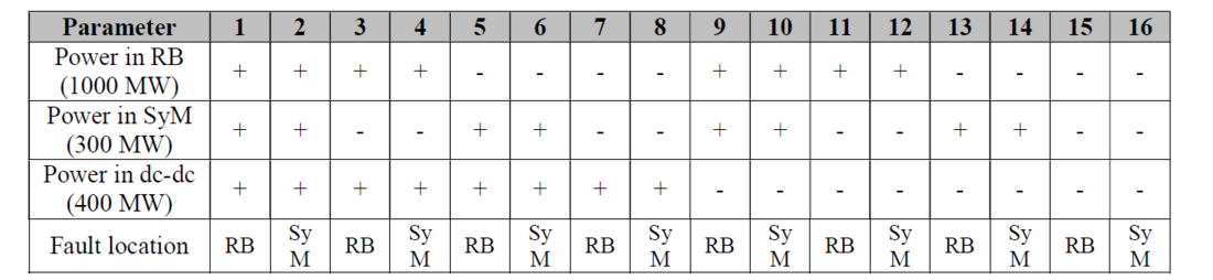
Table 2 - Variations of the case study, where the positive conventions (+) are shown in Fig. 7. In the RB and SyM lines from right to left (towards the P-Ctrl stations) and in the dc-dc converter from the RB to the SyM
The simulation starts with nominal voltage and power reference on the RB and SyM lines, 1000 MW and 300 MW respectively. After reaching the steady state, a power reference is sent to the dc-dc converter to exchange power (400 MW) between dc systems in both directions. The simulation results in normal operation are shown in Fig. 8, for case 1: positive power flow in the lines and bidirectional exchange through the dc-dc converter. The results obtained for the other 7 cases are similar: the fluctuations presented in Fig. 8 are representative for all tested normal operation cases. The power exchange measured at the five converter stations are presented in Fig. 8a. It can be seen that the stations in voltage control mode change their power exchange to compensate the power through the dc-dc converter (magenta line), while the stations in power control keep their power exchange invariant as their references have not been changed (solid lines).
Figure 8b shows the voltage variations pole-to-ground on each converter. These perturbations depend on the voltage control tuning on each line (time response of 100 ms) and the rate of change in dc-dc converter power reference (2.3 GW/s, i.e. 3.3 p.u./s). In this case study, the voltage perturbations do not exceed 6% of the nominal line voltage, but they can be reduced if a decreased slope in the dc-dc converter power references is used.
Figure 8c shows the variations in the average total energy stored in every converter. In this case, the power controlled station in the SyM line has the higher energy variation (11.4%) followed by the voltage control station in the same line. These energy variations are the consequence of the VCC, which helps to keep the dc voltage regulation using the converter internal energy. For the converters in the RB line, the VCC is implemented only in the V-Ctrl station. The P-Ctrl station controls the total converter energy with the ac power (Fig.4b) therefore, P-Ctrl in RB keeps its energy constant. Similar to the voltage variation, these energy disturbances can be attenuated by reducing the slope in the dc-dc converter power reference, but for this paper the slope remains unchanged to test the systems responses to fast power transients.
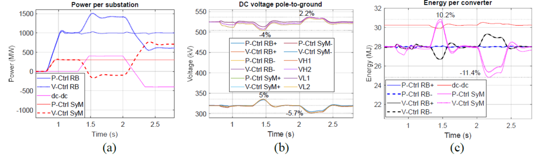
Figure 8 - Simulation results in normal operation for the case 1. (a) Power per station. (b) Pole-to-ground voltage, positive (+) or negative (-) measured at the different converter terminals in the system (the negative poles were inversed to simplify the visualization). (c) Total energy in the converters
Regarding the fault simulations, the starting sequence is the same, but the dc-dc converter only exchanges power in one direction: positive from RB to SyM and negative in the opposite direction. After reaching the steady state, a fault of 1 Ω to ground is simulated (at 2s), at the terminals of the P-Ctrl RB+ or V-Ctrl SyM as shown in Fig. 7. The results presented in Fig. 9 are the worst cases per station found when a fault in the RB line is simulated (odd cases of Table 2). During the fault, the voltage in the faulted pole drops to zero as shown in Fig. 9a. At the fault instant (t=2s), the negative pole in the RB has an increased voltage reaching -880 kV for the 15th case (see Fig. 9b). The steady state voltage for this pole stabilizes at -762 kV, which represents 1.45 p.u., similar to the results found in [5]. On the SyM side (Fig. 9b-c), the voltages do not exceed ±10% of the nominal voltage for any case, which agrees with the initial control design.
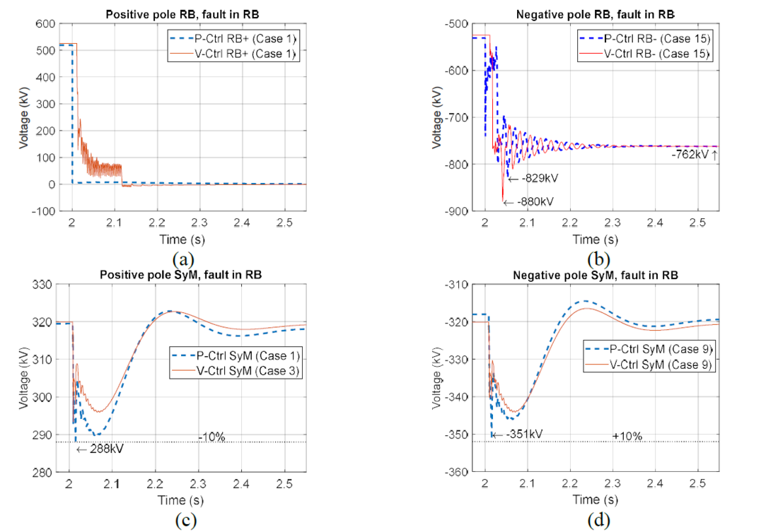
Figure 9 - Dc voltages pole-to-ground during and after the fault on the RB side (worst cases). (a) positive pole in RB. (b) Negative pole RB. (c) Positive pole SyM. (d) Negative pole SyM
Figure 10 presents the higher dc currents measured at the RB (Fig. 10a), the SyM (Fig. 10b) and the dc-dc converter (Fig. 10c) terminals for the cases when the fault is on the RB side. Figure 10a shows a peak of 8 kA for the currents measured in V-Ctrl RB+ converter. It is worth mentioning that the converter protection strategy blocks the MMC under 400μs after the fault. The currents observed in V-Ctrl RB+ continue to rise until the ACCB is opened: after 2.1 s, which illustrates how the ac currents feed the fault in that pole. On the SyM side (Fig. 10b) the currents have a perturbation due to the loss of power from/to the dc-dc converter (t = 2s). After the transient, the currents reach the operation point where the voltage controlled stations exchange the same power as the power controlled stations (behavior expected without the use of dc-dc). Figures 9b-c and 10b illustrate that the dc-dc converter can act as a firewall during a fault in a RB, as the healthy link continues normal operation once the dc-dc converter is blocked, irrespectively of the state of the other link.
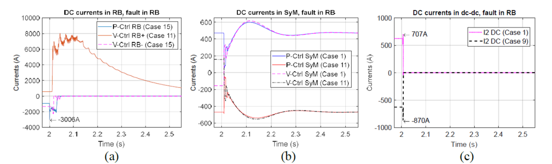
Figure 10 - Dc currents during and after the fault on the RB side (worst cases). (a) currents in all four MMCs in the RB line. (b) Currents measured in the SyM. (c) Currents measured in the dc-dc
Figure 11 shows the worst voltages measured at the stations, for the simulations when the fault is on the SyM line (even cases in Table 2). The voltages on the RB exceed the 10% of variation with respect to the nominal value for the cases 8 (Fig. 11b), 10 and 12 (Fig. 11a). These fluctuations are consequence of the RB control scheme, which is sensitive to the variations in the dc side due to the terminal control in the P-Ctrl station. The voltage fluctuations depend on the rate of change of the power delivered by the dc-dc converter. These variations can be reduced if the dc-dc converter reduce the disturbances during the fault. Reference [14] present a control strategy that allows the converter to control the fault current, decreasing the magnitude of the disturbances. On the SyM side, the positive pole voltage drops to zero (Fig. 11c), while the negative pole presents an overvoltage of 2 p.u. (Fig. 11d). The results were obtained without surge arresters, but the implementation of overvoltage protections can reduce the voltage peak and steady state values.
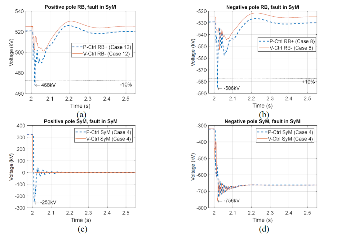
Figure 11 - Dc voltages pole-to-ground during and after the fault on the RB side (worst cases). (a) positive pole in RB. (b) Negative pole RB. (c) Positive pole SyM. (d) Negative pole SyM
Figure 12a shows the currents in the RB and how they recover steady state values after the fault. Similar to the results presented in Fig. 10, the power and voltage controlled stations find the operation point where the dc-dc is absent. Figure 12b presents the dc currents in the SyM and how they are blocked in a short time (less than 50 ms). The currents through the dc-dc converter are presented in Fig. 12c. The dc-dc converter is able to isolate the RB line during a fault in the SyM allowing the first to regain steady state operation without triggering any protection.
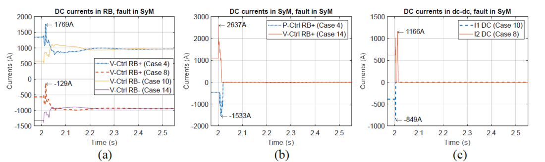
Figure 12 - Dc currents during and after the fault on the RB side (all even cases on Table 2). (a) currents in all four MMCs in the RB line. (b) Currents measured in the SyM. (c) Currents measured in the dc-dc
Figure 13 presents the energy in the dc-dc converter during and after the 16 faults cases of Table 2. Figure 13a presents the cases for a fault on the RB side. In these scenarios the energy variations are near 1% of the nominal value (30.24 MJ). For the cases where the fault is located on the SyM (Fig. 13b), the energy in the converter increases up to 110% as a consequence of the FBSMs charging as they stop the fault current.
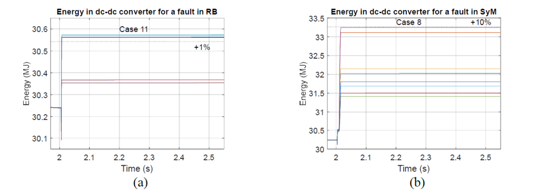
Figure 13 - Energy in the dc-dc converter for (a) a fault in the RB (odd cases of Table 2) and (b) a fault in the SyM (even cases of Table 2)
6. Conclusions
Dc-dc converters are needed for the interconnection between dc systems with different characteristics. The present publication explores the hypothetical interconnection between the NordLink (rigid bipole - RB) and Cobra Cable (symmetric monopole – SyM), using a non-isolated dc-dc converter.
The case study was modelled and simulated in Matlab/Simulink. The power flow in the lines and through the dc-dc converter was changed to simulate 8 possible normal conditions. These initial simulations validated that the exchange of power between the two lines does not trip any protection. After validating the converter behavior in normal operation, a set of 16 fault cases were simulated. Satisfactory results were obtained for the dc-dc converter firewall capability: in case of a fault in a line, the dc-dc converter is able to stop the fault propagation to the healthy system. This firewall capability was validated independently of the power flow direction or the fault location. If enough FBSMs are installed in the dc-dc converter, the firewall capability can be ensured without the presence of dc circuit breakers.
The interconnected lines do not require major adjustments to operate in an interconnected system using a dc-dc converter. The control strategy implemented in the dc-dc converter can be adapted to guarantee the normal operation of the initial lines, and its protection strategy can be design to operate before the line protections. A fast power exchange between dc lines was tested in this paper disturbing the operation of the lines without triggering the fault protections. A slower rate of change can be implemented to reduce the disturbances on the system.
The case study proposed in this paper did not change the grounding strategy and reference points of the initial links. A dc reference is found on the RB and an ac reference on the SyM line. In this particular case, no problems were found, but further studies must be carried to check the impact of multiple reference points on the protection strategy and isolation coordination.
Further studies should evaluate the impact of the ac faults on the dc-dc converter control strategy and fault detection algorithm. Additional fault studies should be done to assess the dc-dc converter behavior under different fault conditions. Different types of faults and locations should be tested. Supplementary studies can be done for the degraded operation, where a fault in the interconnected system leads to the isolation of a portion of a line (e.g. a three-terminal system or the RB reconfiguration into an asymmetric monopole - isolating the faulted converter).
Acknowledgment
This work has been supported by a grant overseen by the French National Research Agency (ANR) as part of the “Investissements d’Avenir” Program (ANE-ITE-002-01).
References
- CIGRE WG. B4.52, “HVDC Grid Feasibility Study.” CIGRE, Apr-2013 [Online]. Available: https://ecigre. org/publication/533-hvdc-grid-feasibility-study
- J. D. Páez, D. Frey, J. Maneiro, S. Bacha, and P. Dworakowski, “Overview of DC–DC Converters Dedicated to HVdc Grids,” IEEE Transactions on Power Delivery, vol. 34, no. 1, pp. 119–128, Feb. 2019.
- D. Jovcic, P. Dworakowski, G. Kish, A. Jamshidi Far, A. Nami Abb, A. Darbandi, and X. Guillaud, “Case Study of Non-Isolated MMC DC-DC Converter in HVDC Grids,” in CIGRE Symposium 2019, 2019.
- D. Gómez, J. D. Páez, M. Cheah-Mane, J. Maneiro, P. Dworakowski, O. Gomis-Bellmunt, and F. Morel, “Requirements for interconnection of HVDC links with DC-DC converters,” in IECON 2019-45th Annual Conference of the IEEE Industrial Electronics Society, 2019, vol. 1, pp. 4854–4860.
- M. Goertz, C. Hirsching, S. Wenig, K. M. Schäfer, S. Beckle, J. Reisbeck, M. Kahl, M. Suriyah, and T. Leibfried, “Analysis of overvoltage levels in the rigid bipolar MMC-HVDC configuration,” in 15th IET International Conference on AC and DC Power Transmission (ACDC 2019), 2019, pp. 1–6.
- G. J. Kish and P. W. Lehn, “Modeling techniques for dynamic and steady-state analysis of modular multilevel DC/DC converters,” IEEE Transactions on Power Delivery, vol. 31, no. 6, pp. 2502–2510, 2015.
- G. J. Kish, M. Ranjram, and P. W. Lehn, “A Modular Multilevel DC/DC Converter With Fault Blocking Capability for HVDC Interconnects,” IEEE Transactions on Power Electronics, vol. 30, no. 1, pp. 148– 162, Jan. 2015.
- T. Lüth, M. M. Merlin, T. C. Green, F. Hassan, and C. D. Barker, “High-frequency operation of a DC/AC/DC system for HVDC applications,” IEEE Transactions on Power Electronics, vol. 29, no. 8, pp. 4107–4115, 2013.
- F. Sasongko, M. Hagiwara, and H. Akagi, “A front-to-front (FTF) system consisting of two modular multilevel cascade converters based on double-star chopper-cells,” in 2013 1st International Future Energy Electronics Conference (IFEEC), 2013, pp. 488–493.
- hitachi ABB Power Grid, “NordLink.” [Online]. Available: https://www.hitachiabbpowergrids. com/references/hvdc/nordlink
- B. Tourgoutian and A. Alefragkis, “Design considerations for the COBRAcable HVDC interconnector,” in IET International Conference on Resilience of Transmission and Distribution Networks (RTDN 2017), 2017, pp. 1–7.
- [12] K. Shinoda, A. Benchaib, J. Dai, and X. Guillaud, “Virtual capacitor control: mitigation of DC voltage fluctuations in MMC-based HVdc systems,” IEEE Transactions on Power Delivery, vol. 33, no. 1, pp. 455– 465, 2017.
- C. Hirsching, M. Goertz, S. Wenig, S. Beckler, M. Suriyah, and T. Leibfried, “On control and balancing of MMC-HVdc links in rigid bipolar configuration,” in 15th IET International Conference on AC and DC Power Transmission (ACDC 2019), 2019, pp. 1–6.
- M. Cheah-Mane, J. Arevalo-Soler, E. P. Araujo, and O. Gomis-Bellmunt, “Energy-based control of a DC Modular Multilevel Converter for HVDC grids,” IEEE Transactions on Power Delivery, 2019.
- H. Zhang, D. Jovcic, W. Lin, and A. J. Far, “Average value MMC model with accurate blocked state and cell charging/discharging dynamics,” in 2016 4th International Symposium on Environmental Friendly Energies and Applications (EFEA), 2016, pp. 1–6.
- F. Xinkai, Z. Baohui, and W. Yanting, “Fast electromagnetic transient simulation models of full-bridge modular multilevel converter,” in 2016 IEEE PES Asia-Pacific Power and Energy Engineering Conference (APPEEC), 2016, pp. 998–1002.
- B. Paths, “Best Paths, Transmission for sustainability.” Best Paths [Online]. Available: http://www.bestpaths-project.eu/
- K. Sharifabadi, L. Harnefors, H.-P. Nee, S. Norrga, and R. Teodorescu, Design, control, and application of modular multilevel converters for HVDC transmission systems. John Wiley & Sons, 2016.
- S. Dennetière, S. Nguefeu, H. Saad, and J. Mahseredjian, “Modeling of modular multilevel converters for the France-Spain link,” Star, vol. 2, no. 3, p. 4, 2013.