Comparison of electrical clearance between Japan and other countries
Authors
T. YAMANAKA - Electric Power Development Co., Ltd., Japan
Y. SHIMOMURA - Kyushu Electric Power Transmission and Distribution Co., Inc., Japan (Former affiliation: The Japan Electric Association)
S. MURAKAMI - J-POWER Transmission Network Co., Ltd., Japan
K. FUJITA - Tohoku Electric Power Network Co., Inc., Japan
Y. KOYAMA - Chubu Electric Power Grid Co., Inc., Japan

Summary
The electrical clearance (D) in Japan is calculated from the sum of Safety distance (Ds) and Minimum air clearance required to prevent a disruptive discharge between phase conductors and objects at earth potential during fast front or slow front overvoltages (Del). Del is ‘clearance increment’ and depends on the system voltage. This is the same idea as in foreign countries. The interpretation of the technical standards (Ministerial Ordinance) for electrical appliances and materials (hereinafter referred to as ‘Interpretation of Technical Standards’) stipulates a clearance value that increases with rising voltage (hereinafter referred to as ‘clearance increment’). The clearance increment varies depending on the safety distance and has been set as 12 cm / 10 kV above 60 kV for other structures and trees, and 15 cm / 10 kV above 35 kV for buildings.
The clearance increments in other countries are generally set to about 6 cm / 10 kV, so as the voltage rises, Japan's clearance is clearly larger than in other countries. When the clearance was established in Japan in 1959, there were no 500 kV overhead transmission lines (hereinafter referred to as ‘OHL’), and the clearance of extra-high voltage OHL had not been sufficiently studied. Since then, the number of OHL of 170 kV class and above has been increasing rapidly. It was thought that if these clearances could be reviewed to be comparable to those in other countries, the height of towers would be reduced and the area of tree trimming that interferes with OHL would be reduced, leading to cost savings in the construction and maintenance of OHL. Based on these circumstances, in order to explore the possibility of reviewing the electrical clearance of EHV OHL in Japan, we conducted overseas survey on the regulations of Germany, France, Canada, and the United States and then not only the electrical clearance values but also basis for their setting were investigated and compared to Japanese one. The overseas survey confirmed that there would be no safety problem with relaxing the electrical clearance of OHL exceeding 170 kV, hence we applied to the regulatory authority to change it. As a result, on February 25, 2020, it was approved to amend the clearance increment (Del) to 6 cm / 10 kV with respect to the electrical clearance between overhead transmission line exceeding 170 kV and building, road, other electric wire, tree.
This amendment of the electrical clearance will reduce the height of 500 kV towers by about 2 m, thereby reducing the cost of materials, transportation, and assembly of the towers. In addition, by reviewing the electrical clearance from the conductor to the tree, the area of trees to be cut down as obstacles can be reduced, especially when the conductor swings sideways in the wind. Therefore, it will reduce not only the compensation cost of new OHL, but also the maintenance cost of existing OHL.
This paper describes the results of the studies and investigations that formed the basis for the first revision of Japan's electrical clearances in 61 years, and the effects of the regulatory changes on the design and cost of OHL.
Keywords
Overhead transmission line - Clearance - Minimum insulation gap - Interpretation of technical standards for electrical facility in Japan - National Electrical Safety Code (NESC) - CSA - EN 50341-1 - EN 50341-2-4 - EN 50341-2-8 - VDE - UTE C111. Introduction
The interpretation of the technical standards (Ministerial Ordinance) for electrical appliances and materials (hereinafter referred to as ‘Interpretation of Technical Standards’) stipulates a clearance value that increases with rising voltage (hereinafter referred to as ‘clearance increment’). The clearance increments vary depending on the type of object approaching the conductor, with ‘other structures*1 and trees’ set at 12 cm / 10 kV and ‘buildings’ at 15 cm / 10 kV. However, in other countries, they are generally set at around 6 cm / 10 kV, and as the voltage class increases, the deviation from the Japanese clearance becomes more pronounced.
This standard value was set in 1959, but at that time, 500 kV overhead lines did not exist and the clearance for EHV lines was not fully considered. Since 1959, the number of EHV OHL above 170 kV has been increasing rapidly. Therefore, if this clearance can be revised, the cost of construction and maintenance of OHL will be reduced.
*1 In Interpretation of Technical Standards, structures other than ’buildings, roads (except those with infrequent vehicular and human traffic), pedestrian bridges, railroads, tracks, cableways, overhead communication lines, low-voltage (600 V or less) or high-voltage (7,000 V or less) overhead electric lines, low-voltage or high-voltage train lines, and other electric lines exceeding 7,000 V’ are defined as ‘other structures’.
2. Comparison of clearance distance in EHV overhead transmission lines
The clearance (D) is calculated from the sum of Safety distance (Ds) and Minimum air clearance required to prevent a disruptive discharge between phase conductors and objects at earth potential during fast front or slow front overvoltages (Del). Del is ‘clearance increment’ and depends on the system voltage. (Table 1).
The safety distance (Ds) was calculated from model cases in each country, and there was no significant difference between Japan and other countries for buildings and other structures. On the other hand, the clearance increment (Del) is 6.4 cm / 10 kV in the United States and Canada, 6.2 cm / 10 kV in Germany (average of 35 kV or more), and 7.5 cm / 10 kV in France, so the clearance increment in Japan is remarkably large. As a result of this, the divergence from Japan's clearance becomes striking as the voltage class grows larger (Figure 1 and 2).
Table 1 - Calculation formula for the clearance (D) and References
| Country | Calculation formula for the clearance (D) | Reference |
|---|---|---|
| United States | D*2 = Ds + Del | - National Electrical Safety Code (NESC) |
| Canada | D*2 = Ds + Del | - CSA standard C22.3 No.1-15 Overhead Systems |
| Germany | D = Ds + Del | - EN 50341-1, EN 50341-2-4 (VDE 0210-1, VDE 0210-2-4) |
| France | D = Ds + Del*3 | - EN 50341-1, EN 50341-2-8 (UTE C11-001, ARRÊTÉ TECHNIQUE) |
| Japan | D = Ds + Del*4 | - Technical standards for electrical facility in Japan |
*2 Phase to ground voltage
*3 Consider the probability of approaching the conductor
*4 This value varies depending on the object that must be kept away from the conductor
3. The clearance increment (DEL)
3.1. Clearance increments in Japan (old standard)
The clearance increment in Japanese old standard was set to increase 15 cm per every 10 kV exceeding 35 kV for buildings, and 12 cm per every 10 kV exceeding 60 kV for other structures and trees [1]. This value was set by the Electric Construction Standards of 1959. According to the description in the standard, the basis of the clearance increment of 12 cm / 10 kV is as follows. It had to have a safety margin slightly greater than the Minimum insulation gap*5 of 6 cm / 10 kV and the Standard insulation gap*6 of 10 cm / 10 kV and also refer the other countries values. Therefore the value was decided to adopt the intermediate value between those up to 1958 (20 cm / cm) and the Minimum insulation gap (Figure 3). Furthermore, since it was considered that the value for buildings needed a safety margin more than other structures, 15 cm / 10 kV was adopted.
*5 ‘The minimum insulation gap’ is defined as the air gap that does not cause flashover for the assumed switching surge and short-time overvoltage.
*6 ‘The standard insulation gap’ is defined as the air gap that allows lightning-induced flashover to occur between the arc horns and not between the wires and the tower.
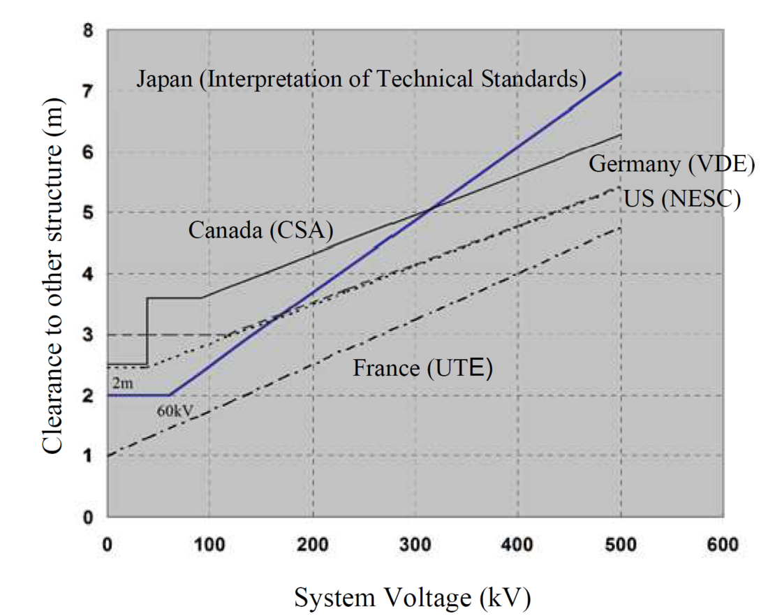
Figure 1*7: Comparison of electrical clearance with other countries (other structures)
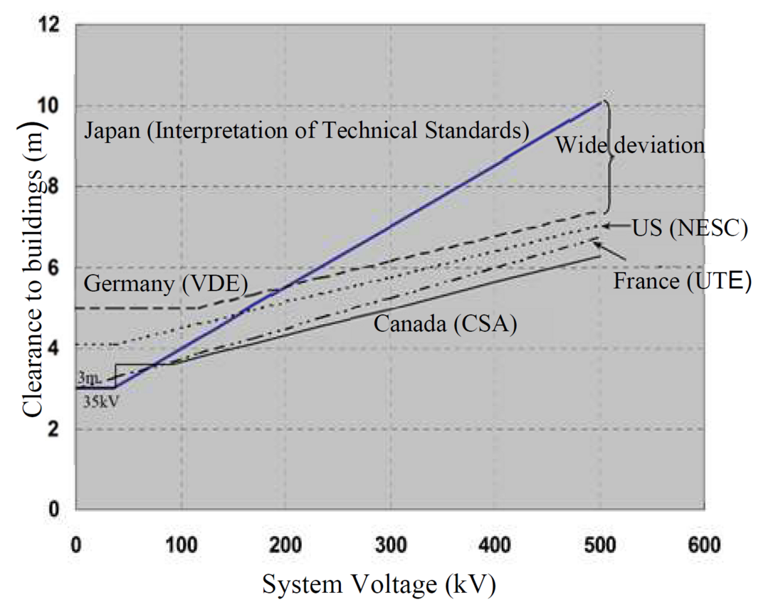
Figure 2*7: Comparison of electrical clearance with other countries (buildings)
*7 Figures 1 and 2 are taken from Figures 3.1 and 3.3 in Electrical clearance for extra high voltage overhead transmission lines exceeding 170 kV, JESC E2012 (2013), (in Japanese) [13]
3.2. Clearance increment in the U.S.
The current U.S. clearance increment is set to 1.0 cm / kV above the ground voltage of 22 kV [2]. In 1949, it was to 0.5 inch (1.27 cm) / kV, but in the 1980s it was amended to a 0.4 inch (1.0 cm) / kV [3]. The 0.5 inch and 0.4 inch per 1 kV of ground voltage can be calculated from the Guard Zone specified in the NESC. Guard Zone means the Minimum insulation gap to the charged section (Figure 4). The Guard Zone has been updated with the advancing research and technology on switching surges since around 1960, and presumably as a result, the clearance increment was amended from 0.5 inch / kV to 0.4 inch / kV. In addition, considering the switching surge factor used in EHV OHL, the clearance increment exceeding 35 kV is 0.64 cm / kV.
3.3. Clearance increment in Canada
The clearance increment in Canada is set at 1.0 cm / kV when the ground voltage exceeds 22 kV, and is equivalent to the United States clearance increment [4]. The CSA standard adopted in Canada cites a number of IEEE standards, and the clearance increment has presumably been set in the same way as the US NESC standard.
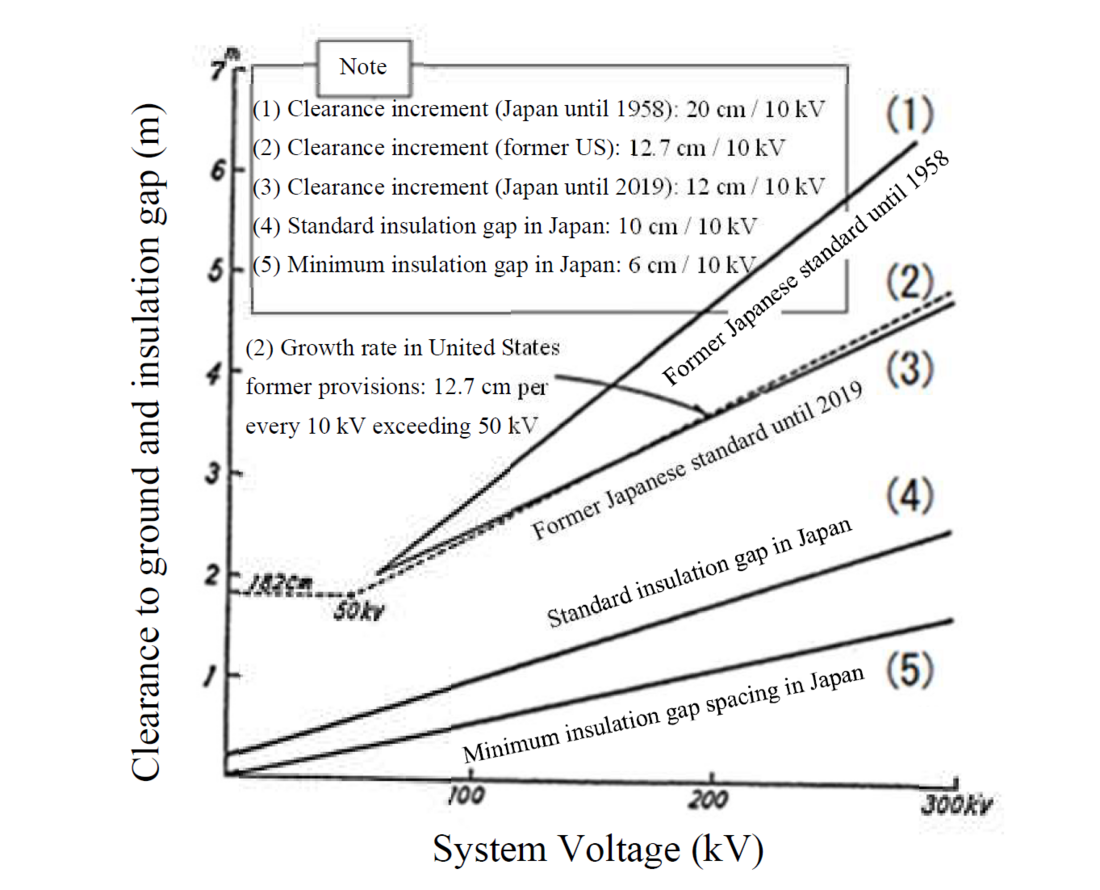
Figure 3 - Clearance increment and insulation gap that change with increasing system voltage
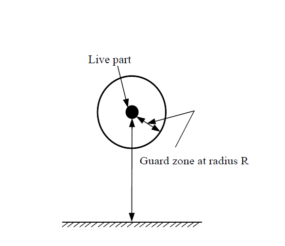
Figure 4 - Clearance from live parts
3.4. Clearance increment in Germany
The German clearance increment is based on the European reference EN standards [5][6][7]. This value is specified as the Minimum insulation gap based on the European empirical method, and was determined by analyzing values from about 30 countries that cooperated in establishing the standard (Table 2).
Table 2 - Minimum air clearance Del
| Highest system voltage Us (kV) | Del (m) |
|---|---|
| 36 | 0.35 |
| 52 | 0.60 |
| 72.5 | 0.70 |
| 100 | 0.90 |
| 123 | 1.00 |
| 145 | 1.20 |
| 170 | 1.30 |
| 245 | 1.70 |
| 300 | 2.10 |
| 420 | 2.80 |
| 525 | 3.50 |
3.5. Clearance increment in France
The clearance increment in France considers the probability of approaching the conductor. The adopted value depends on the circumstances, so if the probability of approaching the conductor is low, there is an increase of 0.25 cm / kV, for medium probability the increase is 0.50 cm / kV, and for high probability the increase is 0.75 cm / kV [8][9].
4. Minimum isolation gap in Japan
In 1958, Japan's first proposed recommendation for the insulation design standard was drafted. This proposed recommendation was drafted with reference to the technical documents and test data of other countries, and the Minimum insulation gap is set as the clearance to withstand switching surges and sustained abnormal voltages [10]. Later, based on advances in research and technology on switching surges, insulation design guidelines were published in 1966 and 1986 [11] [12]. When the clearance increment is calculated from Minimum insulation gap against switching impulse voltage in Japan, it is 5.2 cm / 10 kV (Figure 5). A more conservative value would be 6.0 cm / 10 kV, which is equivalent to the clearance increment in other countries.
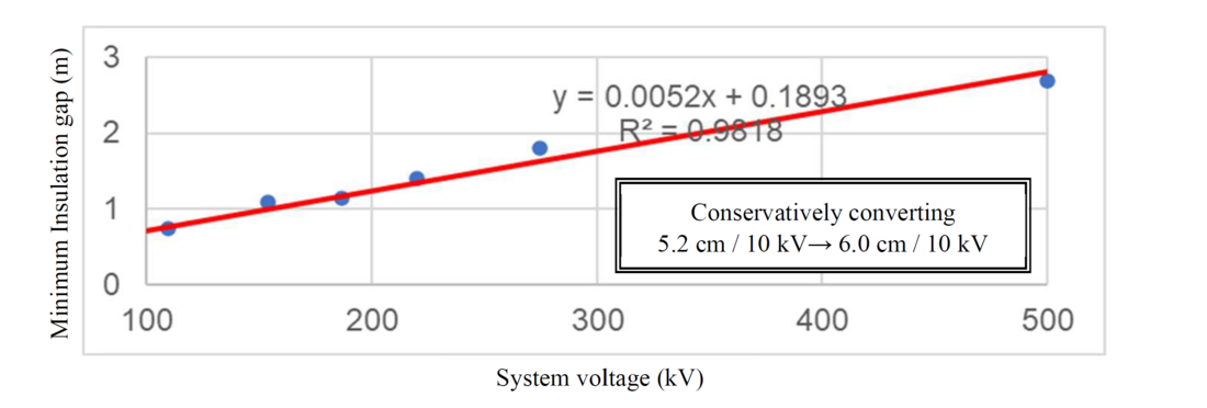
Figure 5 - Calculation the clearance increment from Minimum insulation gap against switching impulse voltage in Japan
5. Comparison of electrical clearance between new and old standards
Comparing the clearance increment before and after the amendment of the interpretation of the Japanese technical standards, the clearances could be reduced by about 2 to 3 m for 500 kV (Figure 6 and 7). As a result, tower height of 500 kV OHL can be reduced by about 2 m.
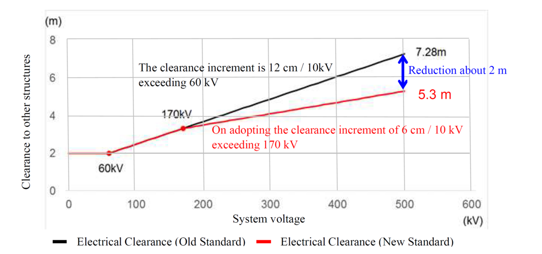
Figure 6 - Clearance distance before and after amendment (other structures)
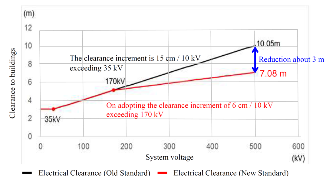
Figure 7 - Clearance distance before and after amendment (buildings)
6. Potential for flashovers resulting from the amendement of the clearance increment
The possibility of flashover from the conductor to other objects after the clearance amendment was examined as follows, in the case of lightning striking the conductor (lower phase). The standard insulation gap is an airgap set to ensure that flashovers caused by lightning occur between arcing horns rather than between conductor and tower, and it is calculated by the following equation [12].
L=1.115 x Z+0.021
Where,
L: Standard insulation gap (m), Z: Arcing horn gap (m)
In the new standard, a clearance exceeding the standard insulation gap has been assured, and there is no potential for flashovers to other objects (Table 3, Figure 8 and 9).
Table 3 - Standard insulation gap and clearance
| System voltage (kV) | Standard insulation gap (m) [10] | Clearance to objects (m) | |||
| New standard | Old standard | ||||
| Other structures 6 cm / 10 kV | Buildings 6 cm / 10 kV | Other structures 12 cm / 10 kV | Buildings 15 cm / 10 kV | ||
| 187 | 1.53 (100%) | 3.44 (225%) | 5.22 (341%) | 3.56 (233%) | 5.40 (353%) |
| 220 | 2.36 (100%) | 3.62 (153%) | 5.40 (229%) | 3.92 (166%) | 5.85 (248%) |
| 275 | 3.03 (100%) | 3.98 (131%) | 5.76 (190%) | 4.64 (153%) | 6.60 (218%) |
| 500 | 4.82 (100%) | 5.30 (110%) | 7.08 (147%) | 7.28 (151%) | 10.05 (209%) |
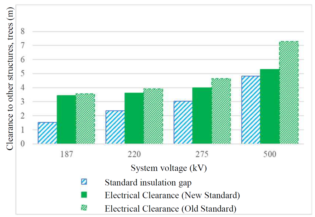
Figure 8 - Comparison of the clearance (between conductor and other structures, trees)
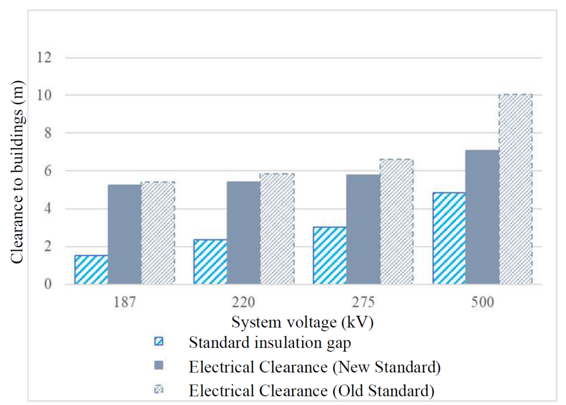
Figure 9 - Comparison of the clearance (between conductor and buildings)
7. The effect of regulatory amendment in electrical clearances on the design and cost of overhead transmission lines
7.1. Estimated construction cost reduction for overhead transmission lines
By amending the electrical clearance between the EHV OHL and the trees, the clearance between the conductor of the 500 kV OHL in the mountainous area and the trees can be reduced by 1.98 m. Therefore, the height of the tower can be reduced by about 2 m (See Figure 10). The reduction of the tower height by 2 m means that approximately 2 tons of steel per tower can be reduced, and the cost of tower materials and erection work can also be reduced. This amendment will contribute to a reduction of about 1 % of the total construction cost of the 500 kV OHL in Japan [13]. Since most of the EHV OHL in Japan pass through mountainous areas, the economic effect of the revised clearance regulation is incredibly significant. The electrical clearance of OHL in urban areas (the minimum height above ground of OHL)is determined by the regulation value of electric field strength at the ground surface. It has been confirmed through actual measurements that the EMF level is not a problem if the OHL satisfies this electric field strength regulation value.
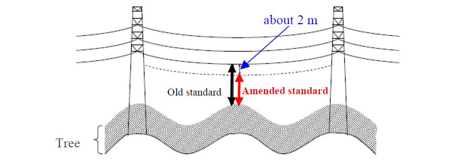
Figure 10 - Reduction effect of EHV overhead transmission line towers passing through mountainous areas
7.2. Effect of reducing the area of trees that are cut down as obstacles to conductor
The expected reduction in the area of tree falling on conductors due to the amendment of electrical clearance is described as follows. The reduction ratio in the area of tree trimming, determined from the required clearance when the conductor swings 60 degrees and sideways in high winds, is 3.8 % for overhead transmission lines of 170 kV and above, which can be reduce the compensation cost (see Figure 11) [13]. This is not a temporary compensation at the time of OHL construction, but lasts as long as the facility exists, so this economic effect is also significant.
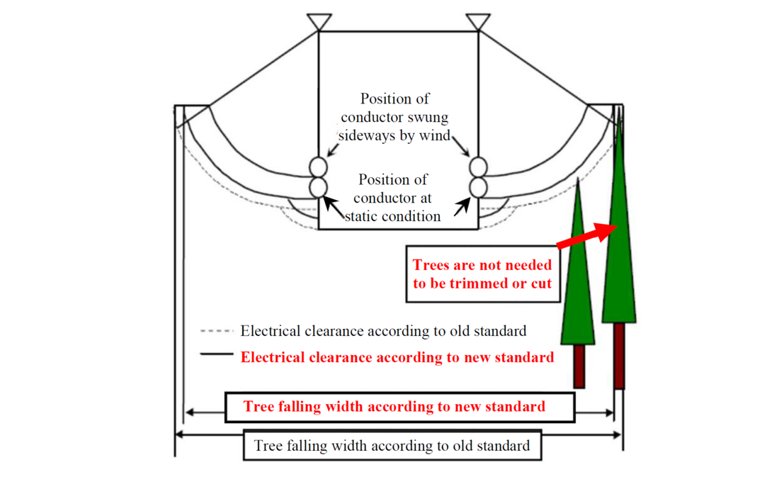
Figure 11 - Comparison of falling width of obstructed trees according to new and old standards
8. Conclusions
As in Japan, the electrical clearance in other countries is calculated based on the standard clearance value plus the clearance increment per 10 kV, but since the Japanese clearance increment used to be larger than in other countries, there was a maximum divergence of about 3 m in 500 kV. The Japanese electrical clearance was amended for the first time in 61 years on February 25, 2020 after many years of study and recent overseas surveys. This will reduce the height of 500 kV towers by about 2 m, which will reduce the material and assembly costs of the towers and reduce the area of trees to be cut down as obstacles. It will not only reduce the cost of constructing new OHL, but also the cost of maintaining the existing one, which will have a significant economic impact.
References
- Technical Standards for Electrical Facility in Japan (in Japanese)
- National Electrical Safety Code (NESC) C2 (2017)
- National Bureau of Standards Handbook H43
- CSA standard C22.3 No.1-15 Overhead Systems (CSA)
- EN 50341-1 Overhead electrical lines exceeding AC 1 kV - Part 1: General requirements - Common specifications
- EN 50341-2-4 Overhead electrical lines exceeding AC 1 kV - Part 2-4: National Normative Aspects (NNA) for GERMANY
- VDE 0210-1 Overhead electrical lines exceeding AC 1 kV Part 1: General requirements – Common specifications
- EN 50341-2-8 Overhead electrical lines exceeding AC 1 kV - Part 2-8: National Normative Aspects (NNA) for France
- UTE C11-001 Conditions techniques auxquelles doivent satisfaire les distributions d'énergie électrique - Arrêté technique
- Insulation Design Standard for Power Transmission Lines, IEEJ Recommendation, 1958 (in Japanese)
- Insulation Design Guidelines for Overhead Transmission Lines (Part I), IEEJ Technical Report, 1966 (in Japanese)
- Insulation Design Guidelines for Overhead Transmission Lines (Part II), IEEJ Technical Report, 1986 (in Japanese)
- Electrical clearance for extra high voltage overhead transmission lines exceeding 170 kV, JESC E2012 (2013), (in Japanese)