Distinctive Downsizing of Cone-Type Insulating Spacer for 245 kV Class GIS by Functional Insulating Materials
Authors
K. OKAMOTO - Fuji Electric Co., Ltd.
N. HAYAKAWA - Nagoya University
M. HIKITA - Kyushu Institute of Technology
H. OKUBO - Aichi Institute of Technology
K. KATO - National Institute of Technology, Niihama College
N. OSAWA - Kanazawa Institute of Technology
K. WATANABE - Nagase ChemteX Co.
K. ADACHI - Central Research Institute of Electric Power Industry

Summary
The downsizing of gas-insulated switchgear (GIS) and gas insulated transmission line (GIL) will lead to a reduction in their cost, installation area, manufacturing energy, and use of SF6, which is an extremely potent greenhouse gas. However, there is a limitation in the insulation techniques by the conventional composite material technology.
To begin with, in order to investigate the possibility of downsizing of a cone-type insulating spacer of GIS, flashover voltage (FOV) characteristics by standard lightning impulse (LI) voltage in the SF6 gas were studied by fabricating a 1/4 size mini-model cone-type spacers applying nano-micro composite (NMC) materials and/or permittivity (ε) functionally graded materials (ε-FGM).
For NMC materials, epoxy resin with SiO2 micro-filler (MC) was filled with 1 vol % of nanofiller (SiO2, TiO2, SrTiO3, Al2O3) to fabricate a 1/4 size cone-type spacer model. In the case of positive LI voltage in 0.5 MPa-abs, the scale parameter (η) of the Weibull distribution of the FOV of the nTiO2-filled and nSrTiO3-filled NMC materials was increased by 12% and 20%, respectively, compared to the MC (without nano-filler).
For ε-FGM, 1/4 size cone type insulating spacer was also produced as well as NMC, and FOV was measured. ε-FGMs with relative permittivities (εr) distributed between 12.7 and 4 were designed and fabricated using SrTiO3 and SiO2 micro-fillers. The FOV at 0.5 MPa-abs under a negative LI voltage of ε-FGM spacer is higher than that of a uniform permittivity sample by approximately 23 %. Thus, it was clarified, both NMC and ε-FGM techniques can improve the insulating properties of the cone-type insulating spacers, and especially, it was drastically for FGM.
Furthermore, by applying ε-FGM technique, an insulation spacer of actual the size reduction by 30% in diameter compared with that used in conventional 245 kV class GIS was achieved, and withstand LI voltage characteristics were verified. The permittivity distribution of the ε-FGM spacer was optimized by an inverse calculation technique with a newly developed electric field analysis method. The maximum electric field stress in SF6 gas of FGM spacer is decreased to 0.74 a.u., compare to the stress (1.0 a.u.) at the same location of Uniform permittivity spacer, and decreased to the same level as 0.77 a.u. on the coaxial HV conductor. Finally, the FGM spacer with distributed permittivity of εr=10-4 using SrTiO3 and SiO2 fillers was fabricated. Under negative standard LI voltage with 0.5 MPa-abs, the FOV of FGM spacer was to be 21-29 % higher than that of Uniform spacer with εr=4. In addition, as a result of withstanding voltage test of LI ±1050 kV 15 times which was a type test of standard LI voltage with 0.6 MPa-abs, of 245 kV class GIS regulated in IEC 606944, there was no flashover, and the standard requirement was satisfied.
Keywords
Insulating Spacer - GIS - nano-micro composite - functionally graded materials - flashover voltage1. Introduction
The downsizing of gas-insulated switchgear (GIS) and gas insulated transmission line (GIL) will lead to a reduction in their cost, installation area, manufacturing energy, and use of SF6, which is an extremely potent greenhouse gas. However, there are limitations to conventional composite materials technology. Therefore, Fuji Electric Co., Ltd has participated in the "Development of Innovative Functional Insulating Materials for Electric Power Apparatus" project subsidized by the New Energy and Industrial Technology Development Organization (NEDO) since 2017, and it has collaborated with several universities and materials manufacturers to use nano-micro composite (NMC) material and permittivity functionally graded material (FGM) to improve the performance of insulating spacers [1]-[7]. Fig. 1 shows an image of an insulating bus comprising a cone-type insulating spacer and tanks. The target value for downsizing this spacer is 30% of its diameter and 50% by volume.
First, in order to clarify whether NMC is applied to the cone type insulating spacer and the insulating property is improved, a 1/4 size cone-type spacer model was fabricated, and FOV in the SF6 gas was measured by standard lightning impulse voltage.
Next, to clarify whether ε-FGM is applied to the cone type insulating spacer and the insulating property is improved, similarly a 1/4 size cone-type spacer model was fabricated, and the FOV was measured. And the inverse analysis system of permittivity distribution was newly developed in order to form the electric field grading by ε-FGM accurately and efficiently.
Finally, an actual size cone-type insulating spacer of 245 kV class GIS applied the ε-FGM, was fabricated, and the FOV in the SF6 gas was measured by standard lightning impulse voltage.
This paper describes the results and discussions of these studies.
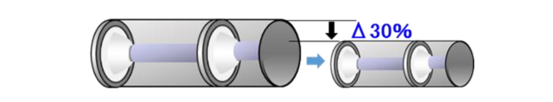
Figure 1 - Concept of downsizing of a cone-type insulating spacer for GIS
2. Study with cone-type insulating spacer made of nanocomposites
2.1. Experimental
Table 1 lists the nano-fillers used in the experiment. Bisphenol A epoxy resin was used as the main agent, alicyclic acid anhydride was used as the curing agent, and dimethylbenzylamine (BDMA) was used as the catalyst. The micro-filler was filled with 47 vol% SiO2 (hereafter referred to as (a) MC). Four kinds of nano-fillers, SiO2, TiO2, SrTiO3, and Al2O3, were selected and filled to 1 vol% of MC. Here, the above samples are referred to as (b) NMC-nSiO2, (c) NMC-nTiO2, (d) NMC-nSrTiO3, and (e) NMC-nAl2O3, respectively.
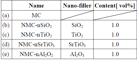
Table 1 - List of nanofillers for each sample
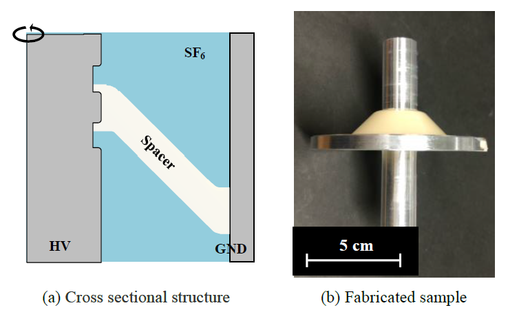
Figure 2 - 1/4 size cone-type insulating spacer
Fig. 2 shows the cross-sectional structure and a fabricated sample of a 1/4 size cone-type insulating spacer. Each resin and catalyst was prepared by dispersing the filler in a planetary centrifugal mixer, casting them in a mold, and heating and curing them in a constant-temperature oven. The structure of the center conductor was designed to suppress the electric field enhancement of the triple junction by providing a shield for electric field relaxation inside and outside the spacer on the center conductor side.
The sample was placed in a pressure vessel, evacuated, and sealed with SF6 gas to 0.5 MPa-abs. The negative and positive standard lightning impulse voltage (1.2/50 μs) was used as the test voltage. The voltage application was carried out by the step by step voltage raising method. A standard lightning impulse voltage was applied in 300 kV to 20 kV steps, and the flashover generated voltage was measured as FOV. The test was stopped when the superposition of the discharge path occurred.
2.2. Results and discussion
Fig. 3 shows the Weibull distribution of the FOV in SF6 gas at positive (black paint) and negative (white blanking) impulse voltages. Table 2 lists the Weibull parameters η and m . The table shows that the η of each NMC spacer was almost the same as that of MC with negative impulse application, while the η of NMC-nTiO2 and NMC-nSrTiO3 was improved by 12% and 20%, respectively, compared to MC with positive impulse application.
It has been reported that the initial electron emission from the insulating spacer contributes to the polarity effect appearing in the impulse FOV of the epoxy spacer in GIS. However, this study shows that the deep electron trap level is formed by nanocomposite from the analysis by quantum chemical calculation, and that this improves the FOV in the model electrode system in SF6 gas. From the above research report, the effect of deep trap level formation by the nanofiller addition on the flashover voltage characteristics of the insulation spacer model obtained in this study is discussed from the viewpoint of creeping discharge generation and progress. That is, the following are assumed: FOV generation by the initial electron supply from the insulating spacer surface and the streamer generation condition of Schumann and the creeping discharge process from the streamer progress at the insulator interface to the dielectric breakdown.
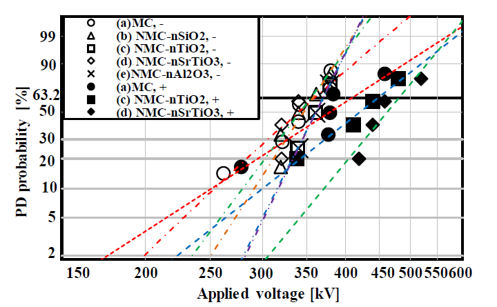
Figure 3 - Weibull plots of FOV by NMC in 1/4 size cone-type spacer model
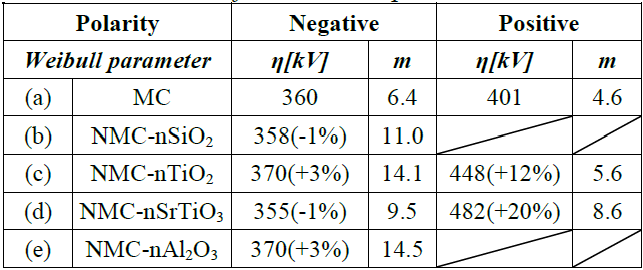
Table 2 - List of Weibull parameters under each test condition for each sample
Fig. 4(a) shows an example of the discharge trace after the flashover test, while Fig. 4(b) and 4(c) show a model diagram of the creeping discharge mechanism at negative and positive impulse voltages for the insulating spacer model. As shown in Fig. 3 and Table 2, the FOV of the nano-filler added spacer sample hardly changed in the negative polarity, while the FOV of NMC-nTiO2 and NMC-nSrTiO3 greatly improved in the positive polarity. That is, when the HV conductor had a negative polarity, the FOV improvement effect was not observed by the addition of nanofiller because the initial electron injection from the HV conductor became the main factor of the FOV determination. However, when the HV conductor had a positive polarity, the initial electron emission from the deep trap formed on the surface of the insulating spacer was suppressed to improve the FOV. The assumption of the initial electron suppression was based on the deep trap level formation by the addition of nanoparticles obtained from quantum chemical calculations [8].
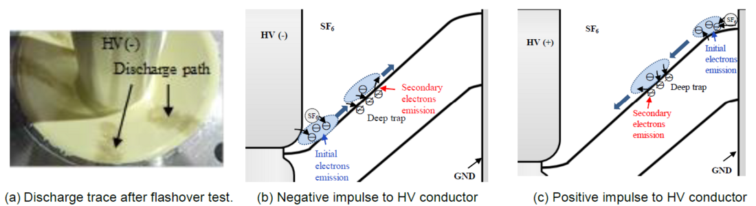
Figure 4 - Example of discharge trace after flashover test and discharge model diagram of polarity effect in GIS spacer model
3. Study with cone-type insulating spacer made of functionally graded material
3.1. Design of ε-FGM by inverse analysis
The permittivity distribution of ε-FGM was manually determined using the results of previous studies coupled with electromagnetic theory. For proper relaxation of electric field stress, many trials on the electric field analysis for various kind of permittivity distribution of ε-FGM were needed. To optimize the electric field grading by ε-FGM quickly and efficiently, the inverse analysis of permittivity distribution was used.
In this study, a cone-type FGM spacer made by variable compounding casting was used. For this reason, it was assumed that the dielectric permittivity was in the axial direction, and its distribution in the radial direction was uniform. Here, as shown in Fig. 5(a), the inside of the spacer is divided into small regions, and each dielectric permittivity is set to εi. The potential at the boundary of different regions on the surface of the spacer is defined as Vi.
Because each region is formed into a thin plate shape, it can be replaced with a parallel plate capacitor. That is, it can be expressed by a series capacitance, as shown in Fig. 5(b). To approximate the desired electric field intensity distribution, the desired dielectric permittivity distribution can be attained using an inverse solution approach by considering a method to assign a voltage to each capacitance by changing the dielectric permittivity. In the analysis, an appropriate dielectric permittivity distribution was given to the spacer, and electric field analysis was performed using the finite element method to obtain the potential sharing of each part of the spacer. From this potential sharing, the dielectric permittivity distribution of each region of the spacer was attained and used to perform electric field analysis. This process was repeated to gradually reduce the electric field intensity. Once the electric field intensity distribution converged, the calculation was terminated.
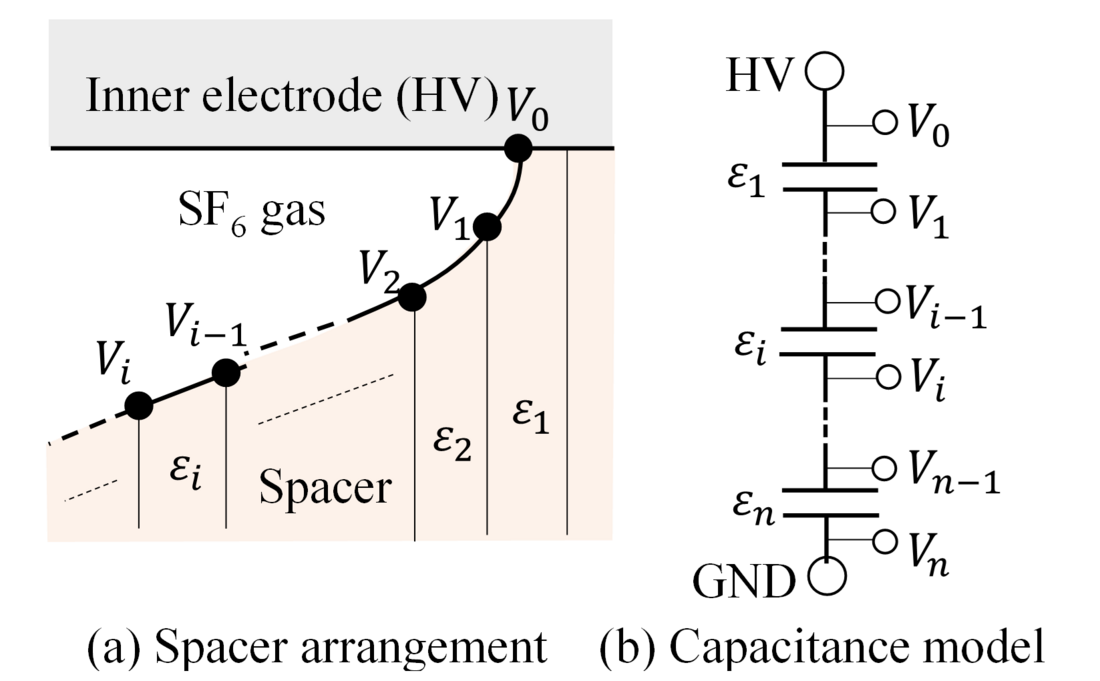
Figure 5 - Potential distribution around spacer
Fig. 6(a) shows the calculation model. The ratio of the inner diameter to the outer diameter of the coaxial cylindrical conductor of the GIS was set to 1: 3. The shield electrode was applied to the center conductor of the cone-type spacer at a spacer inclination angle of 45°. The inside of the spacer was divided into small regions from # 1 to # 34, and the permittivity of each region was obtained by inverse solution calculation. An initial uniform distribution of the relative dielectric permittivity of 4.0 was given.
Fig. 6(b) shows the electric field intensity in and around the spacer obtained as a result of the inverse solution. When the dielectric permittivity in the spacer was uniform, the electric field reached its maximum at the corner of shield electrode. On the other hand, when the dielectric permittivity distribution obtained by the inverse solution was given, this electric field could be greatly reduced. As described above, the maximum electric field around the spacer was reduced by the inverse solution calculation method of the dielectric permittivity distribution, and as a result, the electric field value of the infinite length bus without the spacer (coaxial theoretical electric field) could be reduced [9].

Figure 6 - Calculation model and results (electric field strength)
3.2. Experimental
For ε-FGM, a 1/4 cone-type insulating spacer was fabricated by a flexible mixture casting method as shown in Fig. 7, and the FOV was measured. The ε-FGM spacer had a seamless distribution of εr = 12.7 - 4.0 (red line) from the HV conductor to the grounded tank in the radial direction. In comparison with the ε-FGM spacer, the uniform spacer had a permittivity εr = 4.0. We used two kinds of fillers, SrTiO3 and SiO2, and their composite with epoxy resin. SrTiO3 had a large permittivity of εr=332 and, as the main filler, was used to determine the εr distribution of the ε-FGM spacer. The mixing ratio of the two composites was continuously controlled with two syringe pumps and a static mixer, and then combined to create a cone-type ε-FGM spacer (diameter: 60 mm), as shown in Fig. 8. A uniform spacer with the same shape and size as the ε-FGM spacer was fabricated using only the SiO2 composite.
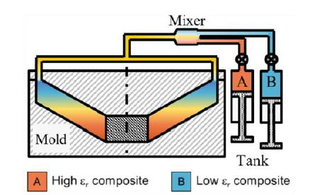
Figure 7 - Concept of flexible mixture method
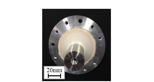
Figure 8 - 1/4 size cone-type ε-FGM insulating spacer
3.3. Results and discussions
The fabricated cone-type insulating spacer was placed in SF6 gas (0.5 MPa-abs), and a standard lightning impulse voltage was applied in 300 kV to 20 kV steps, and the flashover generated voltage was measured as FOV. The measured and estimated values according to the volume-time theory are shown in Fig. 9. In the actual measured values, the average values of 6 uniform and 14 uniform spacers for ε-FGM and the FOV of the uniform spacer are in agreement with the estimated values. Additionally, though the measured FOV of the ε-FGM spacer was higher than that of the uniform spacer, the maximum value of the measured FOV is only slightly lower than its estimated value. This is likely due to the production error in the dielectric permittivity of the ε-FGM spacer. The maximum experimental value of the ε-FGM spacer was verified to be 23% higher than that of the uniform spacer, which was also consistent with the estimated value of the flashover voltage.
Moreover, the discharge of the uniform spacer is all creeping discharge on the concave side, and it is suggested that the high-voltage shield edge, which has the largest electric field, is the origin. On the other hand, the discharge of the ε-FGM spacer is gap discharge on the concave side (11 pieces) and a creeping discharge on the convex side (3 pieces), suggesting that the dielectric permittivity distribution of ε-FGM relaxes the electric field at the shield edge of the high-voltage side and improves the flashover voltage [10].
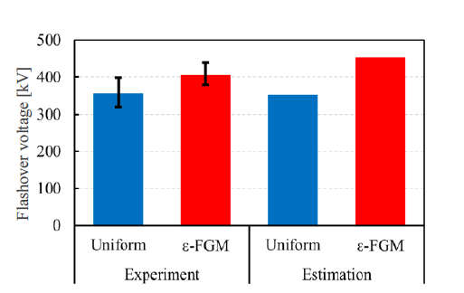
Figure 9 - Improvement of FOV by ε-FGM in 1/4 size cone-type spacer model
4. Study with actual size cone-type insulating spacer
4.1. Design of cone-type FGM spacer
For the ε-FGM, an actual size cone-type insulating spacer of 245 kV class GIS was fabricated, and the FOV was measured. The permittivity distribution of the ε-FGM spacer was optimized by an inverse calculation technique with a newly developed electric field analysis method.
Fig. 10 shows the cross section of Actual size cone-type FGM spacer. The outer diameters of HV conductor is 90 mm and the inner diameter of grounded tank is 240 mm, respectively. The configuration of the grounded tank around the spacer is modified in consideration of the actual GIS spacer. The relative permittivity (εr) is reduced in 6 steps from εr=10 around the HV conductor to εr=4 around the grounded tank.
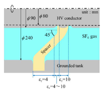
Figure 10 - Actual size cone-type spacer model
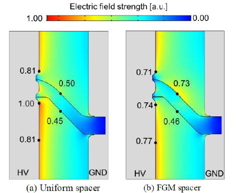
Figure 11 - Electric field distribution
Fig. 11(a) shows the electric field distribution around the Uniform spacer with the same configuration as the FGM spacer and a constant εr=4, whereas Fig. 11(b) shows the electric field distribution around the FGM spacer in Fig. 10. The electric field strength at the shield edge of HV conductor in the concave side of Uniform spacer is defined as 1.0 a.u., which is higher than those on the coaxial HV conductor and on the spacer surface in the concave and convex sides. On the other hand, the electric field strength at the same point of FGM spacer is 0.74 a.u., which is 26 % lower than that of Uniform spacer and almost the same as 0.77 a.u. on the coaxial HV conductor. Note that the electric field strength on the spacer surface in the convex side is increased to 0.73 a.u. from 0.50 a.u. of Uniform spacer, which means that the electric field distribution in SF6 gas around the FGM spacer is equalized owing to its permittivity distribution.
4.2. Fabrication of actual size cone-type FGM spacer
As shown in Table 3, 2 kinds of composite materials are prepared in advance: a SrTiO3 filler (εr=332) containing high permittivity composite material and a SiO2 filler (εr=4) containing low permittivity composite material. By changing the ratio of these two kinds of composite materials and mixing them, the permittivity was changed, and by casting them into a mold sequentially, a cone-type FGM spacer with the permittivity graded from εr=10 to εr=4 was produced.
Fig. 12(a) shows a uniform spacer of εr=4, and Fig. 12(b) shows a FGM spacer of εr=10-4. In Fig. 12(b), the white region is εr=10, the black region is εr=4, and the gray region between them is a graded region.
Filler material | SrTiO3 | SiO2 |
Mean diameter | 1.0 – 1.5μm | 1.5μm |
Relative permittivity | 332 | 4 |
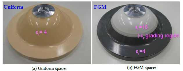
Figure 12 - Fabricated actual size cone-type spacer
4.3. Results and discussions
The fabricated cone-type spacer was installed in a tank filled with SF6 gas at 0.4-0.6 MPa-abs and exposed to negative standard lightning impulse voltage. The applied peak voltage started at about 0.5 a.u., denoted by an arbitrary unit, and increased by about 0.05 a.u. 3 samples of Uniform spacer and 2 samples of FGM spacers were tested.
The cross symbols in Fig. 13 show the measured flashover voltage of Uniform (black) and FGM (red) spacers as a function of SF6 gas. At 0.6 MPa-abs, 2 FGM spacers were flashover at 1.72 a.u., whereas 2 uniform spacers were flashover at 1.4 a.u. and 1.5 a.u. respectively. At 0.5 MPa-abs, one FGM spacer was flashover in the range of 1.57 a.u to 1.67 a.u (acquired five times) whereas one uniform spacer was flashover at 1.2 a.u. Thus, the FOV of FGM spacers were experimentally verified to have the higher by 17-20% than the Uniform spacer at 0.5-0.6MPa-abs.
Fig. 13 also shows the estimated flashover voltage, designated by circle symbols (Uniform: black, FGM: red), based on the Volume-time theory [6]. The dotted line is their approximations. The measured FOV of FGM spacer agreed well with the estimated flashover voltage, respectively.
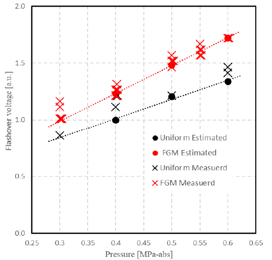
Figure 13 - FOV of cone-type FGM spacer
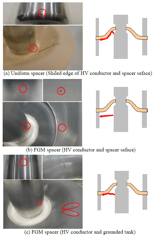
Figure 14 - Flashover traces of cone-type spacers
The flashover characteristics are discussed in terms of flashover traces. Fig. 14 shows the flashover traces of (a) Uniform spacer at 0.6 MPa-abs, (b) FGM spacer at 0.6 MPa-abs and (c) FGM spacer at 0.4 MPa-abs, respectively. The flashover traces of Uniform spacer in Fig. 14(a) were found at the shield edge of HV conductor in the concave side, which corresponds to the point of high electric field strength in Fig. 11(a), as well as on the spacer surface in the concave side. On the other hand, as shown in Fig. 14 (b) and Fig. 14 (c), there were 2 types of patterns of the FGM spacer: discharge from the concave-side coaxial HV conductor to the ground tank, and discharge from the coaxial HV conductor shield edge to the spacer surface near the ground tank.
These results suggest that the flashover of Uniform spacer was a surface discharge originated from the shield edge, whereas the flashover of FGM spacer was a gap discharge between the coaxial cylindrical electrodes. Consequently, the fabricated cone-type FGM spacer could exhibit its flashover voltage improvement effect, compared with the Uniform spacer, owing to the electric field grading and equalization by FGM spacer.
In addition, a voltage withstanding test of 15 times LI ±1050 kV, which is a type test of the standard LI voltage of 245 kV class GIS regulated in IEC 606944, was carried out with the FGM spacer. As the result, there was no flashover, and the standard requirement was satisfied.
5. Conclusions
The summaries of this study are described below.
- As a result of measuring the FOV in SF6 gas at 0.5 MPa-abs with 1/4 size cone-type spacer applying NMC material, it was shown that, for positive impulse voltages, the use of nTiO2 or nSrTiO3 increased the FOV by 12% or 20%, respectively, compared with the MC.
- By the inverse analysis method of the dielectric permittivity distribution, the maximum electric field around the ε-FGM spacer is reduced, and as a result, it is possible to reduce the electric field value to that of the infinite length bus without the spacer.
- FOV of the fabricated 1/4 size ε-FGM cone-type spacer was increased by 23 % compared with that of the uniform spacer in SF6 gas at 0.5 MPa-abs under negative standard lightning impulse voltage.
- An actual-size ε-FGM cone-type spacer with a permittivity graded to 10-4 was fabricated, and the FOV of negative lightning impulse voltage was measured. As a result, it was verified that FOVs of this spacer can be improved by 17-20% compared with a uniform spacer with εr = 4.
It was clarified that both NMC and ε-FGM can improve the insulation characteristics of the cone-type insulating spacer. And, by applying the FGM technology in the range of pressure of 0.5-0.6 MPa-abs in 245 kV class GIS, it was clarified in the actual size that FOV of the FGM spacer increased about 21-29 % over uniform spacer of the conventional technology. That is to say, this indicates that the application of the FGM technology is very effective in gas insulation and gas solid insulation systems such as GIS and GIL, and the target of size reduction of about 30% in comparison with the conventional one at the beginning is expected.
In the future, AC withstand voltage test, partial discharge test, long term withstand voltage test, etc. will be carried out for 30% downsizing of 245 kV class GIS spacer and bus duct configurations.
Acknowledgment
This paper is based on results obtained from a project (JPNP12004) commissioned by the New Energy and Industrial Technology Development Organization (NEDO).
References
- N. Matsuoka, Y. Fuchi, M. Kozako and M. Hikita, “Effect of Permittivity Variation on Surface Flashover of GIS Epoxy Spacer Model in SF6 Gas,” IEEE ICD, pp.96-99, 2016.
- K. Abe, K. Ohzuno, M. Kozako, M. Hikita, H. Mitsudome, H. Yanase and K. Okamoto, “Partial Discharge Inception Voltage Characteristics for Nano-micro Composites under Impulse Voltage in SF6 Gas”, IEEE CEIDP, pp.738-741, 2019.
- Hitoshi Okubo, Hideki Shumiya, Masahiro Ito and Katsumi Kato,“Insulation Performance of Permittivity GradedFGM (Functionally Graded Materials) in SF6 Gas under Lightning Impulse Conditions”, Conference Record of the 2006 IEEE International Symposium on Electrical Insulation, IEEE, pp.332-335, 2006.
- Hitoshi Okubo, Hideki Shumiya, Masahiro Ito and Katsumi Kato, “Optimization Techniques on Permittivity Distribution in Permittivity Graded Solid Insulators”, Conference Record of the 2006 IEEE International Symposium on Electrical Insulation, IEEE, pp. 519-522, 2006.
- H.Okubo, K.Kato, N.Hayakawa, M.Hanai, M.Takei, “Functionally Graded Materials and their Applicationsto High Electric Field Power Equipment”, CIGRE SC D1 – COLLOQUIUM IN HUNGARY BUDAPEST, 2009.
- N. Hayakawa, K. Kato, H. Hama, Y. Hoshina and T. Rokunohe, “Electric Field Grading Techniques in Power Apparatus Using Functional Materials,” CIGRE Paris Session, D1-309, 2014.
- N. Hayakawa, J. Ishiguro, H. Kojima, K. Kato, and H. Okubo, “Fabrication and Simulation of Permittivity Graded Materials for Electric Field Grading of Gas Insulated Power Apparatus,” IEEE Transactions on Dielectrics and Electrical Insulation, Vol.23, No.1, pp.547-554, 2016.
- Kazuma Abe, Kotaro Ohzuno, Masahiro Kozako, Masayuki Hikita, Hidetaka Masui, Hiroshi Mitsudome, Hironori Yanase and Kenji Okamoto, “Flashover Characteristics of Gas Insulated Switchgear Spacer Model using New Functional Composite Insulating Material,” IEEJ 2019 Technical Meeting on “Dielectrics and Electrical Insulation,” DEI-19-116, 2019.
- K. Kato, H. Kojima, N. Hayakawa, H. Mitsudome, H. Yanase, K. Okamoto and H. Okubo4, “Inverse Analysis of Permittivity Distribution of FGM (Functionally Graded Materials) Insulator in Gaseous Insulation System,” ISH, 2019.
- Y. Miyazaki, A. Izu, Z. Liang, H. Kojima, H. Masui, H. Mitsudome, H. Yanase, K. Okamoto, K Watanabe, K. Kato, N. Hayakawa, “Breakdown Characteristics of Cone-type ε-FGM Spacer for Gas Insulated Switchgears,” ISEIM, 2020.