Eco-design as a systemic innovation method for offshore substations
Authors
D. BOTRUGNO, M. NUNES - RTE

Summary
The energy transition and the fight against climate change are among the crucial challenges of current times and a major focus of RTE's commitment. As a TSO, RTE takes actions to reduce the environmental footprint of its new projects, enhance the flexibility and resilience of the transmission network and facilitate the integration of renewable energies.
RTE believes new approaches are essential in this context in order to innovate and find sustainable solutions to overcome these challenges.
In this light, RTE is extending its efforts through an ambitious and comprehensive eco-design approach. RTE is raising awareness among its teams and disseminating the necessary tools so that taking the environment into account in each decision, along with the technical and economic criteria, becomes engrained in the company’s practices. In 2020, RTE carried out the LCA (Life Cycle Assessment) of an electrical offshore substation, with an expert firm in the field.
This article’s goal is to share the main lessons, both at the methodological and results level, with the CIGRE members. The identification of the main sources of impact and related ways of implementing eco-design are part of the study's deliverables and should enable improvements to be taken since the short term (and along the assets life).
The LCA methodology is based on a multi-step and multi-criteria analysis, from the extraction of raw materials to the end of infrastructure life. The perimeter of the LCA is the full offshore substation (all electrical equipment, auxiliary equipment, platform systems and structures) all over the asset life, except the HV export cables and the IAC cables.
The process is iterative and, over the time, allows to build a quantitative model where the characteristics of each component are identified, the environmental impacts are calculated, all over the asset life. Several alternatives in design have been tested in the model, covering driving choices for the equipment and the infrastructure. The results have enabled RTE to understand the factors that allow to reduce the environmental impact and make the offshore substation as sustainable as possible.
Finally, the future step of implementation are described.
The main ambition is to drive the company choices in design, supply chain, construction, operations and maintenance aspects. The vision is to reduce the environmental footprint of all the infrastructure all over its life cycle, create a positive integration within the environment, foster technical and social innovations, and support new solutions for the sustainable development of a future decarbonized system infrastructure.
Keywords
Offshore – Substation – LCA – Eco-design – Innovation – Environment – Sustainability1. Introduction
As part of the energy transition and more specifically of the offshore renewable energies development, RTE, the French TSO, has extended its activities to the maritime domain and included within its scope the offshore substations for the future French offshore wind-farms (from public tender AO3 awarded in 2019 onwards). In the context of offshore grid connection projects, RTE plays a major role in the planning and development of offshore renewable energies, both at a pilot and commercial scale. According to the multi-year energy programme (French PPE, [1]), the objective of wind power at sea is to achieve a power of approximately 5 GW in 2028. RTE is responsible for financing, designing, building and operating the offshore power infrastructure, its substations (platforms) and HV cables network.
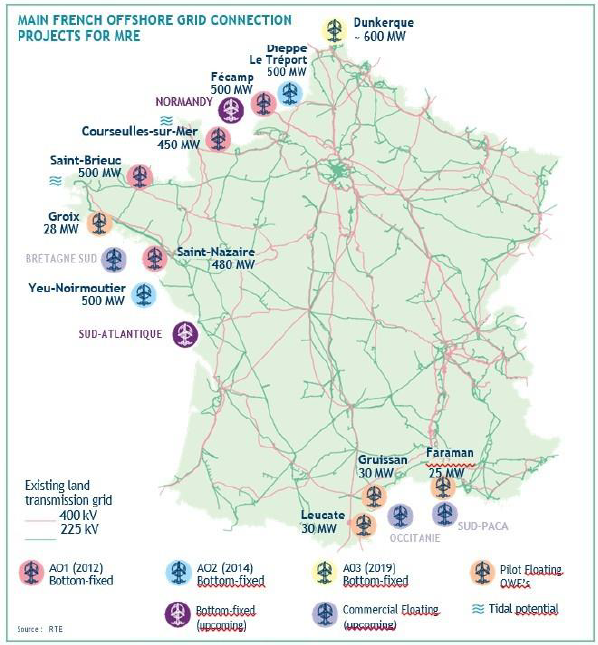
Figure 1 - overview of the main French offshore grid connection projects (as of summer 2021)
RTE is committed to reducing its environmental footprint, and is recognized as such, in particular by stakeholders and auditors in charge of ISO14001 certification renewal. In order to be more efficient, the company has decided to systematically rely on eco-design, deployed throughout all the company processes.
The central objective is to reduce RTE's global environmental footprint in an effective way, thanks to a systemic vision of its impacts over the entire life cycle of each asset and activity. This vision also offers a new leverage in favour of technical-economical optimisation, environmental and societal innovation, and a potential reduction of risks on the value chain.
The process covers the entire scope of RTE’s activities, meaning power infrastructure and assets development, management of the electrical system, and all support services.
This ambition is accompanied by the upstream engagement of a constructive dialogue with stakeholders on these issues, and in particular with RTE suppliers.
Finally, the company is at the heart of an energy transition that faces great uncertainties. Solutions must therefore mobilize the minimum of inputs through the research of focus and sobriety (analysis of the needs), optimize the efficiency, and minimize the impacts of any resulting strategy modification.
This aim is pursued by seeking modularity and reuse / recyclability, by developing an organic approach and methodology at the level of both new power infrastructures to be built and existing to be renewed, and by integrating the context of the evolution of the energy system as a whole.
Among the axes of development of eco-design as a systemic innovation approach, the realization of several LCA studies. LCA’s allow RTE to assess the environmental footprint of the structuring components of the future power infrastructure network, to identify the main impact factors, to evaluate the possible alternative and make considered choices in order to improve their environmental impact over the life of each asset.
Some of the main environmental factors assessed through these LCA’s are: the impact on reduction of greenhouse effect gases, the depletion of natural resources, eutrophication and acidification of seas, and air pollution. These indicators go back into the iteration of design choices, proposing ways and strategies for the eco-design improvement and consolidation into the company processes and assets.
2. The urge of turning environmental challenges into opportunities
Involved since more than a decade into the energy transition, the major players share the responsibility of innovating and preparing the power infrastructure network to implement the EU Green Deal.
Eco-design innovations are crucial for the transition to a sustainable, regenerative, inclusive and circular system. These initiatives can create a wide range of results, improving solutions for a sustainable economy (fighting against climate change and environmental degradation) and fostering the protection of environment (limiting as much as possible negative impacts and creating positive impacts on eco-systems regeneration and biodiversity). They can also support better responses of the system to global matters (including pandemic crisis, and resulting disruption of supply chain).
However, designing an asset in such a way to integrate the environment as one of the key drivers needs to cover all the asset life cycle. Within this context and with the ambitions described in the previous chapter, RTE decided then to perform a life cycle assessment (LCA) for a full offshore substation scope.
Although the LCA method is well-known and used by the industry, our bibliographical study put in evidence that the present work study represents a first-in-its-kind (at the time of writing and as regards to the study perimeter and its approach).
The study combines: a comprehensive perimeter of a full offshore substation (all infrastructure, all equipment, all phases of its life); its iteration to find alternative choices and its systemic approach to design (thus, feeding back the choices and being integrated as a standard practice for all asset strategies).
3. Offshore substation life cycle assessment methodology
The proposed approach is based on the application of the Life Cycle Assessment (LCA) methodology.
The LCA is an internationally standardized method (ISO 14040 to 14044) which allows to assess the quantifiable effects on the environment of a service or product from the extraction of the necessary materials, from its development to end-of-life channels. This is a so-called multi-step method.
The method consists in carrying out an exhaustive assessment of the consumption of natural resources; energy consumption and environmental emissions (releases to air, water, soil and waste) from the entire system studied.
A first step is to draw-up an exhaustive inventory of the inputs-outputs specific to each step of the system. These reports of incoming and outgoing flows are called Life Cycle Inventories (LCI). Each parameter has been calculated based on an offshore substation preliminary basic design developed by RTE. To model the platform, RTE chose an advanced modelling software. The platform model can be easily adapted with new parameters to test new ideas or new platform types. Furthermore, the software includes large environmental databases for each raw material and product. These databases are the link between the data collection and the environmental metrics.
The flows of materials and energy taken and released into the environment at each stage are then weighted and aggregated to quantify environmental impact indicators. For example, the indicator of climate change, expressed in kilograms of CO2 equivalent, results from the sum of greenhouse effect gas emissions weighted by the global warming factors of the various gases.
LCA is thus a multi-criteria methodology: indeed, there is no single environmental score, but the results of the study are presented in the form of several environmental impact indicators.
Given the innovative nature of the study, an iterative process has been put in place to perform the analysis [2]. In the LCA context, an iteration is an action loop making it possible to collect the input data, to model the system in the LCA software, to output the results of the analysis and to interpret them.
Two iterations were carried out:
- The first iteration allowed to define the structuring methodological choices for the realization of LCA (e.g. system boundaries, functional unit, indicators). These first results led to the identification of the factors to refine the conclusions (e.g. additional data, definition of scenarios, sensitivity) as well as to start the identification of eco-design suggestions of improvement / development;
- Several alternatives in design have been tested in the model, covering driving choices for the equipment (e.g. technology / type, materials, place of fabrication, means of transportation) and the infrastructure (e.g. technology / type, materials, place of fabrication, means of transportation) – but also regarding the site conditions (e.g. water depth, nature of soil and scouring properties). This second iteration allowed to freeze the results and their interpretation.
Generally, the main functions of an offshore wind AC substation include:
- Collecting the power produced by the wind turbines generators;
- Stabilizing it and raising the voltage (e.g. from 66 kV to 225 kV);
- Ensuring the electrical protection of the inter-arrays;
- Enabling 225 kV transmission to the onshore network, minimizing the transport electrical losses and reducing the number of subsea cables required.
The typical scheme of French offshore grid connections and the position of the OSS are shown in Fig. 2 below.
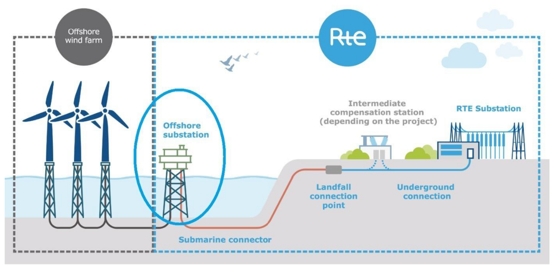
Figure 2 - scheme of French offshore grid connection (and OSS)
An offshore electrical substation is generally composed as follows:
- The topside (usually 3 to 5 floors) which houses the HV/LV electrical equipment, the control and protection equipment, the auxiliary systems, the HV subsea cables connections and the other platforms facilities
- The substructure, which supports the topside. Different types of substructures are possible (monopile, jacket or concrete). The substructure also support the j-tubes for the routing and mechanical protection of subsea cables from underwater to on-board the topside.
- The topside and substructure assembly is fixed to the ground by foundations, the nature of which varies in particular depending on the soil characteristics, the topside size and weight and the meteocean conditions (varying from hollow metal piles driven into the ground to drilled piles, pre-piled or post-piled structures).
As a reference and for entry data to the study, a preliminary basic design develop by RTE was taken. For the electric power equipment, the information provided was more detailed as it was sourced from RTE’s equipment panel.
For the study, the following assumptions are considered for the offshore substation design:
- 600 MW power capacity
- 66 kV / 225 kV voltage levels
- normally unmanned platform
- steel structure and substructure
The LCA perimeter does not include the 225 kV subsea cables. The reason of such choice is that the LCA objective is to isolate and analyse the impacts of the offshore substation from an eco-design perspective. For the same reason, the 66 kV inter-array cables and the rest of offshore wind-farm are also outside the scope of the study, this being under the responsibility of the offshore wind-farm developer company.
In view of the bibliographic analysis carried out as part of this study, the Functional Unit (FU) retained for this study is: "Collect the offshore wind-farm power production and raise voltage level from 66 kV to 225 kV, for an installed capacity of the wind farm of 1 MW and a water depth of 18 m, and for a design life of 25 years".
Finally, more than 98% (by mass) of the elements were modelled and the Circularity Footprint Formula called CFF method (European Commission, DG ENV) was used to model the end of life.
This new method, aimed at evaluating the contribution of products to the circular economy, was developed to modify the rules for allocating the impacts / benefits of recycling as well as to take into account additional factors making it possible to integrate degradation of materials during recycling.
The LCA study and methodology has made the object of a 3-months “critical review” by an independent panel, according to the requirements specified in the ISO14067 standard in the case of possible communication to the general public. A panel of technical experts and stakeholders was constituted, with the aim to challenge and corroborate the eco-design hypotheses, data and suggestions for improvements, and to allow the communication of results to the general public.
4. Life cycle assessment results
Below are presented and discussed some of the main outcomes from the LCA study. The results are given per functional unit and with clear indication of the phase originating the impact, either in the construction phase (fabrication, transportation, installation) or in the service phase (operation and maintenance, deconstruction, recycling / disposal).
4.1. LCA Results - first iteration
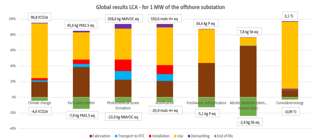
Figure 3 - Global LCA results for the OSS (per functional unit: 1 MW)
Figure 3 diagram shows the global results from the first iteration (base calculation) LCA on an OSS entire cycle. Impacts are shown on a series of indicators considered in the study:
- Climate change
- Particulate matter
- Photochemical ozone formation
- Acidification
- Freshwater eutrophication
- Abiotic depletion (elementary, reserve base)
- Cumulated energy
For each indicator (column), the cumulative max / min values are reported.
The results are differentiated per phase of the OSS life cycle (in different colours). It appears that, for the entirety of the considered indicators, the phases bringing the most significant impacts are the Manufacturing (fabrication) and Operations (O&M) phases.
It is worth observing that the impacts appearing in green in the diagram correspond to negative values (thus indicating impacts which are to be avoided). This is the case of recycled material (used for fabrication instead of new raw materials,) or to the recycling of these materials at the end of asset life (instead of waste disposal), as recorded in the CFF method. On the opposite, the impacts appearing in positive values in the graphs represents impacts onto the environment.
Focusing on the Manufacturing (fabrication) phase, three categories contribute with the most significant impacts (ref. Fig 4):
- The steel structure
- The electric power equipment, mainly:
- Main Power Transformers
- GIS (Gas Insulated Switchgears)
- NEAT (Neutral Earthing Auxiliary Transformers)
- The C&P system and Telecom equipment
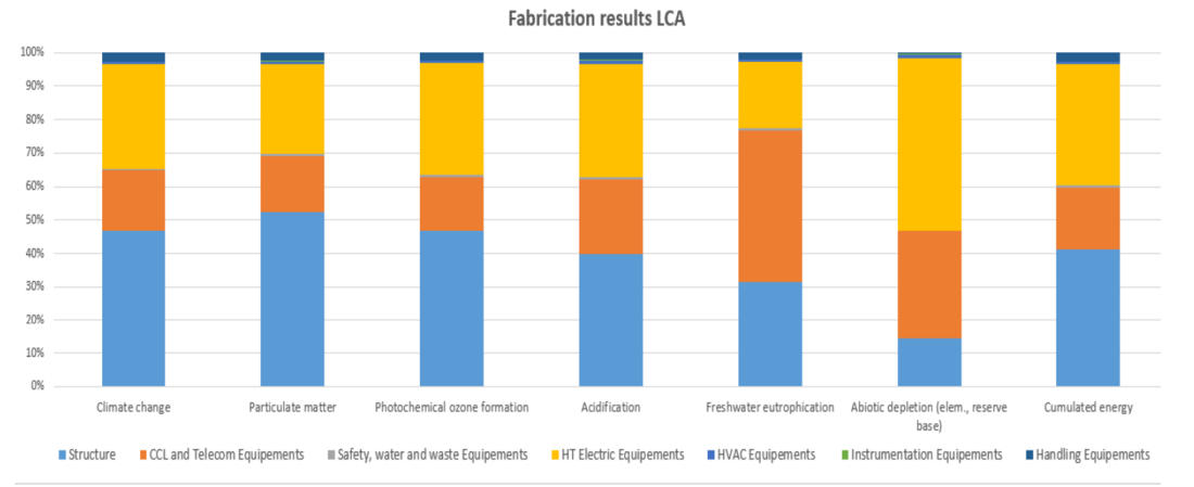
Figure 4 - Results from the manufacturing phase
Steel is of course the main substation structure component. Our results show that steel production, which generates high GHG emissions (4 ton CO2e/ton of primary steel), is responsible for the majority of impacts resulting from the structure.
Electrical equipment production has a significant impact on the reduction of abiotic mineral resources, in particular because of the production of copper contained in transformers and lead contained in batteries.
Manufacturing of C&P equipment and Telecom systems has the greatest contribution to the eutrophication potential of freshwater, due to the manufacture of the electronic components constituting this equipment. Electronic equipment is made up of several metals, including metals that are more or less critical from a geological point of view. The more critical the metal, the more the extraction and refining stages will generate energy consumption and local impacts on natural environments, and especially on freshwater life.
Focusing on the structure fabrication analysis (ref. Fig. 5 below), the piles (in blue) and the jacket (primary structure in red, secondary in grey) have the highest impacts on most of environmental indicators (from climate change to cumulated energy) apart from the decrease in abiotic resources, which is mainly impacted by the painting and corrosion protection systems (for the zinc / aluminium coatings fabrication).
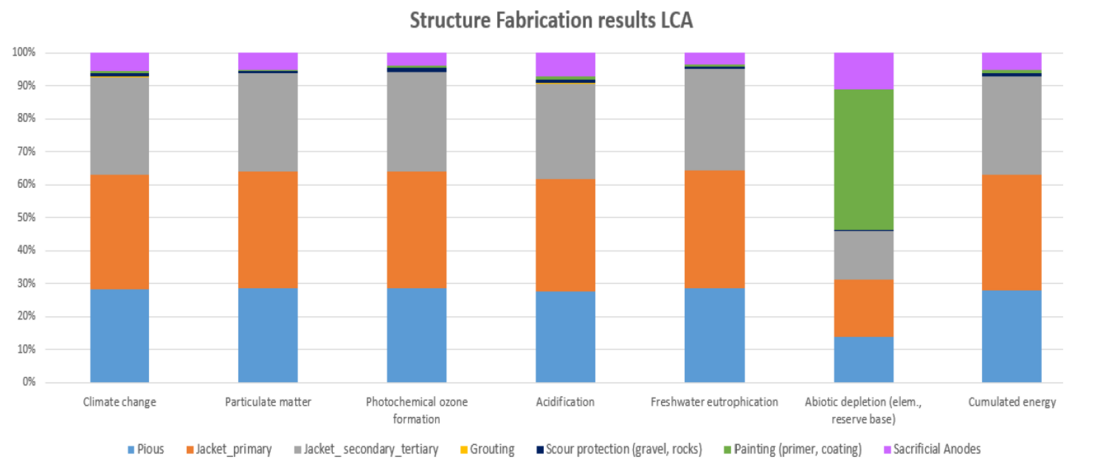
Figure 5 - Results from the structure manufacturing
Within the manufacture of electric power equipment (Fig. 6 below), the Power Transformers and the GIS show the highest impact on all the indicators. For example, Power Transformers represent almost 50% of the impact on climate change and 55% of the impact on acidification and GIS represent 30% on climate change and more than 20% on acidification. This is in particular due to the large quantity of metals that compose them.
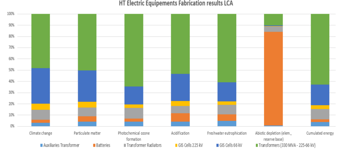
Figure 6 - Results from the electric power equipment manufacturing
Focusing on the Operations (O&M) phase, the impacts of this phase are strongly dominated by the electrical losses of the power transmission asset. With reference to the figure 3) “Results of the global LCA (per functional unit: 1MW)”, those are represented by the yellow contributions (identified as “Use” in the diagram).
Interestingly, it clearly appears the significant contribution of the operations and maintenance life of the asset compared to the construction and installation phases; as a consequence, the positive changes that can be brought on the electrical transmission performance acquire importance in the light of the global LCA.
It is important to note that the results presented above include power transformer losses modelled with a “European Business As Usual 2035” electricity prospective mix. The sensitivity analyses carried out allow to study the impact of modelling losses with either the French electricity mix or a 100% Wind Mix. Because electrical losses are the primary source of impacts, the choice of the electrical mix used to model them is a very important value.
4.2. LCA results – sensitivity analysis
After the first iteration, a total of 11 sensitivity analysis have been performed within the presented study.
Below an overview is given with the main results from 4 of the most influencing key parameters.
A first sensitivity analysis was carried out in order to study the impact of the variation in the offshore wind-farm load factor on the environmental footprint of the substation. Two variants are studied and compared to the reference case (load factor = 47.6%):
- A low variant (load factor equal to approx. 43%)
- A high variant (load factor equal to approx. 52%)
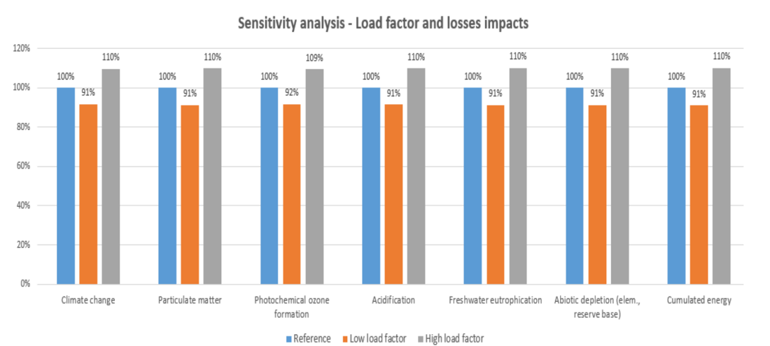
Figure 7 - Variations for the load factor (sensitivity analysis
The graph above (Fig.7) shows the variations in the impact of electric losses, which are the only parameter impacted by the variation of the load factor. For the varying parameter, and for the two analysed scenarios, the differences in results observed are, for all impact indicators, of the order of 10% compared to in the reference scenario. Losses remain a very significant element on the overall environmental impact of the offshore substation, even with a low load factor.
In this study, RTE has chosen as the electricity production mix to be taken into account to assess the environmental impact of electrical losses a mix of average European production by 2035. This choice was made because the electricity network France is interconnected to the European electricity grid, and that the electricity mixes are changing in particular because of the energy transition. However, this choice is not obvious.
The objective of this sensitivity analysis is to study the impact of the choice of the electricity mix modelled for the losses on the results of the study. As indicated in the diagram at Fig.8, the reference case in blue (forecast European Mix BAU 2035) was compared with two variants:
- A 100% wind-powered mix variant (in red)
- The current French mix variant (in grey)
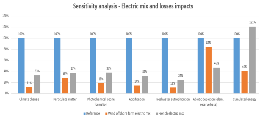
Figure 8 - Variations for Electric Mix (sensitivity analysis)
For the variant parameter, and for the two analysed scenarios, the differences in results observed are quite significant. Thus, the choice of energy mix for loss compensation has a great influence on the results of the study.
This analysis therefore underlines the importance of clarifying the methodological debate on how to account for and model them. Moreover, beyond this methodological debate, it can be said that the main eco-design track for reducing the impacts linked to electrical losses lies in outside the analysed perimeter of the OSS system.
The results of the LCA study are calculated from data related to an OSS equipped with 2 transformers of a certain power capacity. In order to study the influence of the power to be transformed on the LCA and environmental impacts, two variants were modelled, changing the main power transformers number (reference 2 transformers) ref. diagram below (Fig.9):
- An offshore substation variant with 1 transformer (in red);
- An offshore substation variant with 3 transformers (in grey);
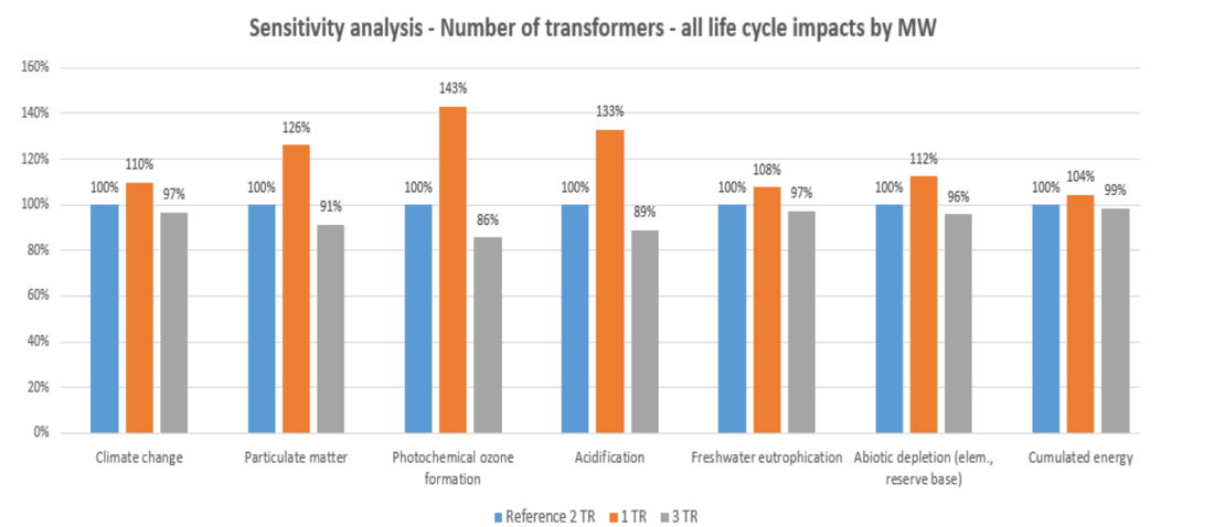
Figure 9 - Variations for number of main power transformers (sensitivity analysis)
Of course, all of the platform's data are impacted by these variants (structure, electric equipment, transports, and losses) and changes taken into account. Results show that the impacts of a substation equipped with a single transformer, weighted to the MW installed, are 7% to 37% higher than for a substation equipped with two transformers.
This is because although the structure and other equipment may be less important to support a single transformer, these quantities are not divided by two. Similarly, the differences in impact (weighted to the MW installed) between a substation equipped with three transformers and the reference case with one transformer are from -1% to -12% depending on the indicators. Thus, the variation in the number of transformers or in power to be transformed does not significantly impact the results of the life cycle analysis presented above.
The OSS offshore installation site and in particular its water depth also play a role. Therefore, a sensitivity analysis case compares the 18 m water-depth reference case (in blue) to 100 m water depth (in red) ref. diagram in Fig.10.
The different impacts brought by this variant mainly affect the OSS manufacturing and installation phases, as well as its end of life. The graph below shows the variations in impacts related to the manufacture, transport and end of life of the substation, which are the parameters impacted by the 100 m water depth case.
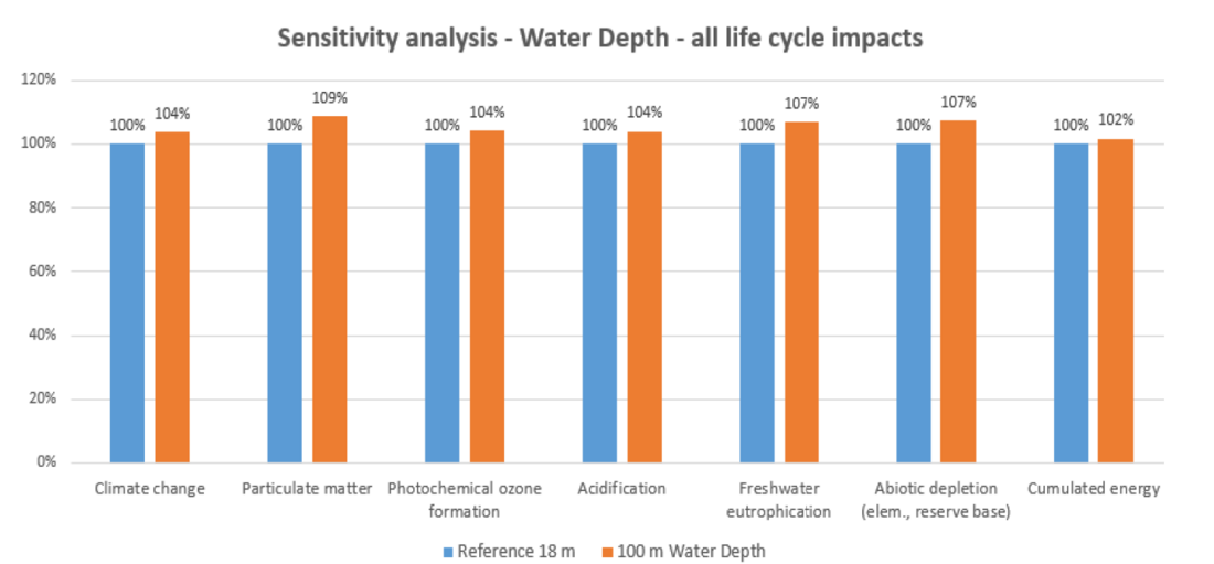
Figure 10 - Variations for water depth at OSS (sensitivity analysis
The change in the OSS structure resulting from 100 m water depth mainly impacts the manufacturing phase, in fact a greater quantity of materials is used to build the structure. On all life cycle, the impacts of the 100m scenario are between 4% and 9% greater than the impacts of the reference scenario depending on the indicators.
This preliminarily indicates that the water depth of the OSS installation site is an important element of the environmental assessment, although additional work is required to refine these results.
4.3. Eco-design alternatives
The results of the investigation for potential alternatives led to identifying suggestions for improving the OSS environmental footprint. Some of the possible hints for improvement are:
- OSS fabrication:
- Minimize substructure and foundations (for example, by choosing a site as shallow as possible, or with floating solutions); enhance weight optimisation / reduction (mainly for steel and scour protection material, but also in general); enable equipment life extension; increase of recovered and re-used quantities at the end of the asset life.
- OSS transportation:
- Optimize global transportation routes / modes of transport; enable cleaner / less polluting fuels for maritime and onshore transportation.
- OSS operation:
- Promote technologies with low electrical loss rates; improve Electricity Mix and purchase greener electricity to compensate for losses; replace SF6 by alternative gases and / or 0% leaks.
- End of life:
- Develop designs in order to increase reuse and recycling ratios
- Promote effective methodologies and treatment to maximise actual recycling.
5. Conclusions
Within the context of offshore wind-farms grid connection projects, the LCA study presented is a first-in-its-kind to date, for several reasons: its comprehensive perimeter of a full offshore substation; its iteration to find alternative choices; its systemic approach to design.
The study enabled RTE to gain an initial view of the environmental impacts of the offshore substation, encompassing the construction phases (manufacturing, transportation, installation) and operations phases (service, maintenance, removal, recycling/disposal) for all its infrastructure and equipment.
The study allowed identifying the elements that contribute the most to these impacts, and documenting a subject which remains little treated in the current scientific literature.
Iterations have been done in the study, in order to pick several alternatives in design both for the electric power equipment and the infrastructure, depending on the technical feasibility and the sensitivity on the overall environmental footprint.
In the detailed engineering phase, RTE will be able to refine this study, by using more precise data and comprehensive information, and remove the limits which have been identified.
To go further, the ambition is to drive the company choices in design, supply chain, construction, operations and maintenance aspects. On the path forward, the software model will allow to manipulate the components based on the technological choices made, and ascertain quantitatively the resulting effects.
Therefore, the future step will be to use the platform model such as an environmental calculator during the detail engineering phase and for other next projects. This environmental calculator will provide the elements allowing to decide on the design choices in the same way as cost, time and risk analyses are conventionally carried out. Intrinsically, the environment will be a part of the equation in the same way as capital and operating expenditure, time and risk are conventionally today.
Moreover, this method shall be extended to all the power transmission network. It will be interesting to see the benefits of a systematic LCA approach on such a full scale system and study how global optimisation can be achieved through a wide range of parameters.
References
- PPE - Décret n° 2020-456 du 21 avril 2020 relatif à la programmation pluriannuelle de l'énergie
- EcoAct and Elys Conseil – OSS LCA Bibliographic analysis and methodology report - 2020