Limits of electric field for composite insulators: state-of-the-art and recent investigations of overhead line insulators purchased by power utilities
AUTHORS
P. SIDENVALL, I. GUTMAN - I2G, Sweden
A. DECKWERTH - 50Hertz, Germany
P. DIAZ, P. MEYER - RTE, France
J.F. GOFFINET - Elia, Belgium
K. HALSAN - Statnett, Norway
M. LEONHARDSBERGER - APG, Austria
M. RADOSAVLJEVIC - Svk, Sweden
P. TRENZ - Bayernwerk, Germany
K. VARLI - Amprion, Germany
K. VALIMAA - Fingrid, Finland

Summary
Hydrophobic properties of composite insulators might be deteriorated in service by continuous corona activity on the housing material itself or by corona from the metal parts directed towards the housing. This issue should be considered already at the design stage, i.e., the electric field should be controlled and limited in a few sensitive areas of an insulator. The criteria for limitation of the electric field in the sensitive areas of composite insulators are well established in the international literature, but not implemented yet in CIGRE/IEC recommendations. In this paper, the criteria are evaluated by electric field calculations of twenty-six commercially available insulators from seven different manufacturers. Laboratory test results then confirm the results of calculation interpretation. It seems that manufacturers of line composite insulators design their products with these criteria in mind. Thus, standardization in relevant IEC standards should be considered, as these criteria are already widely adopted.
1. Introduction and goal
Historically, overhead line composite insulators were first used in polluted areas to reduce or eliminate pollution flashovers. Consequently, their dimensioning only considered the pollution level and excluded possible influence of ageing. A similar situation with dimensioning was revealed after insulators started being installed in relatively clean environments. Their hydrophobic properties were excellent when they were new, but then the hydrophobic properties may be deteriorated in service due to ageing by continuous corona activity on the housing material itself or by corona from the metal parts directed towards the housing. This is a known ageing mechanism specific to composite insulators and should be considered at the design stage of composite insulators together with the selection of grading/corona rings, i.e., the electric field should be controlled and limited in three sensitive areas of an insulator. To achieve a proper (optimal) dimensioning of composite insulators equipped with grading/corona rings, three internationally recognized criteria in critical areas should be considered [1], [2]:
- The limit of electric field on the grading/corona ring and end fitting. Note, the criterion cannot be properly applied for arcing horns because the electrical field might be intentionally increased on them to attract the power arc and protect the hardware.
- The limit of electric field along the housing surface.
- The limit of electric field at the so-called triple point (where air and housing meet the metal end fitting). An example of the triple point adopted from a draft of the revised IEC standard 62217 is shown in Figure 1.
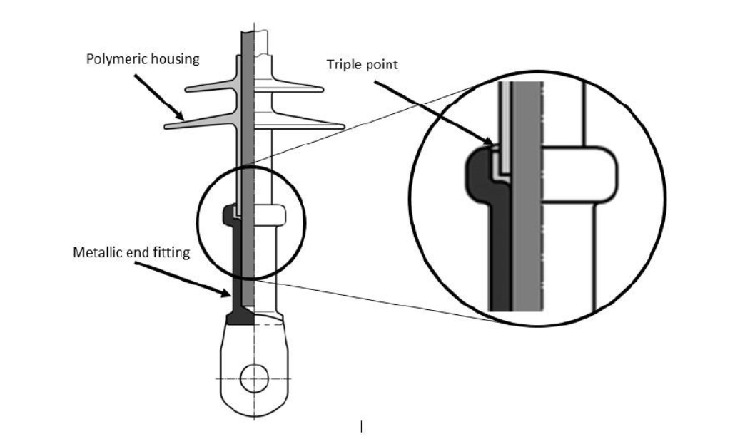
Figure 1 - Illustration of the triple point at the sealing of composite insulator
All three criteria listed above are normally verified by electric field calculations. The first criterion can also be verified by a standard RIV, or corona test described in IEC [3] and [4]. The third criterion cannot be verified by a test but only by calculation. The second criterion (the limit of the electric field along the housing surface) is not verified by any standard test, however, the Water Drop Induced Corona (WDIC) test has been recently developed for this purpose [2], [5]-[8].
The goal of this paper is to update the state-of-the-art of criteria and test methods for the verification of the limitations of the electric field via literature and CIGRE/IEC activities. Additionally, recent results of electric field calculations and tests for the commercially available insulators already purchased by different power utilities are analyzed. Following the latter issue, a group of eight European power companies (both TSOs and DSOs) together with the Independent Insulation Group (I2G, Sweden) is running a collaborative research project intended to benchmark composite insulators. The electric field calculation/verification is one of the activities within the project. The following companies supported this project: 50Hertz (Germany), Amprion (Germany), APG (Austria), E.ON (Germany), Fingrid (Finland), RTE (France), Statnett (Norway), Svenska kraftnät (Sweden).
2. State-of-the-art limitation of electric field for composite insulators
The data regarding the criteria for maximum electric field for composite insulators is very limited. According to CIGRE Technical Brochure (TB) 284 the levels of maximum electric field on the surface of composite insulators (at the tip of the first shed from the end fitting) are estimated as 0,6-1,0 kV/mm [9]. It is, however, stated in the TB that this estimation is too high to ensure a technically safe operation. Earlier EPRI research indicated limiting a value of 0,45 kV/mm [10]. Earlier STRI research indicated limiting at about 0,40 kV/mm [11]. This is valid for hydrophobic surfaces, while continuous corona discharges can be found on hydrophilic surfaces at electric field levels as low as 0,05 kV/mm [11]. This was also observed in I2G/STRI tests. For the maximum electric field from the metal parts (fittings and grading rings) CIGRE TB [9] recommends the limit of 2,2 kV/mm. EPRI indicated 2,1 kV/mm [10], which was often used as a reference value for design purposes. According to internal CIGRE discussions, some utilities use values as low as 1,6 kV/mm. This is to consider for possible non-uniformity of the surface of grading/corona rings during manufacturing or contamination/ageing of the grading/corona rings in service. In the earlier paper, STRI recommended 1,8 kV/mm [11].
Comprehensive research at STRI and EPRI summarizes the findings independently carried out by these two organizations to determine a practical limit for the permissible electric field on composite insulator surfaces for design purposes [1]. This paper published in 2015 covers investigations based on small- and full-scale laboratory and field tests performed by both organizations to refine threshold levels. Results from both natural ageing (STRI) and artificial ageing (EPRI) tests were also considered. The criteria derived from [1] have been used by STRI/I2G for several years and many practical applications:
- The limit of E-field on the grading ring and end fitting 1,8 kV/mm
- The limit of average E-field along the housing surface 0,42 kV/mm
- The limit of E-field at the so-called triple point 0,35 kV/mm.
More than 20 different designs of arrangements with composite insulators were calculated to evaluate the limits of the electric field and, in some cases, to make recommendations for optimal design and positioning of grading rings and arcing horns. Several results of calculations are presented in Figure 2 [2], [5], [6], [11], [12] and some of them were also verified by service observations (normally performed by daylight UV-camera), see Figure 3 [13].
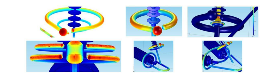
Figure 2 - Typical examples of electric field calculations for different designs of composite insulators (adopted from [2]). Colour scale: 0 – 0,5 kV/mm tangential electric field in top-right image and 0 – 2 kV/mm normal electric field in remaining images. Blue colour indicates low electric field while red colour indicates high electric field
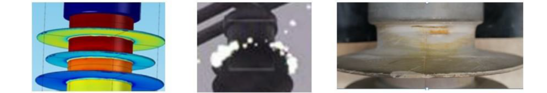
Figure 3 - Left: tangential electric field along insulator (dark red = above 0,5 kV/mm). Middle: inspection by daylight UV camera revealing corona activity on insulator in humid service conditions. Right: deterioration of the first shed of the insulator due to corona (adopted from [13])
To verify the results of limitation of the electric field along the housing based on calculations, a proposal for the test was indicated in [1] and later the procedure for the Water Drop Induced Corona (WDIC) test was developed and verified on several insulator designs, both for single insulator strings and more advanced insulator assemblies [2], [5]-[8], [14], [15], examples are shown in Figure 4. Comparison of electric field calculations and their verification by WDIC testing revealed that the test method is reproducible (confirmed by a Round Robin Test in five international laboratories [8]), representative, repeatable, and cost-effective. Thus, the test fulfils all four formal IEC requirements for the test procedure and will be included in CIGRE TB developed by Working Group (WG) B2.57.
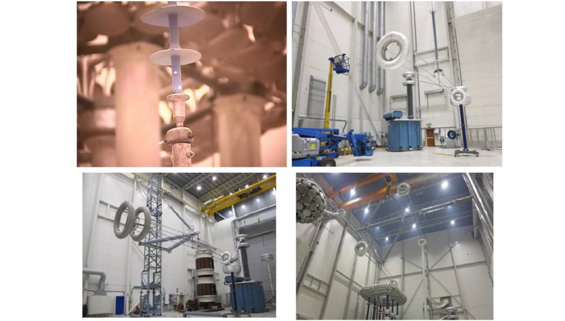
Figure 4 - Examples of insulators/insulated structures verified by WDIC tests. Top-left: 52 kV insulator tested at the development stage of the test; top-right: full-scale 400 kV overhead line insulator; bottom-left: full-scale insulated cross-arm 380 kV; bottom-right: full-scale three-phase “diamond” insulation arrangement 420 kV
As the first step for wider international acceptance, the proposed electric field limits and the WDIC test method were included in the draft of the TB prepared by CIGRE WG B2.57. This WG is currently developing the guidelines for the application of composite overhead line insulators and is expected to be published in the beginning of 2022.
The need to control electric field in critical (sensitive) areas of composite insulators is also for the first time described in the new draft of IEC 62217 (new Annex D) [16], which is under consideration of IEC TC 36 MT 19. The criteria are also discussed in the new draft of IEC 61109 [17], which is under consideration of IEC TC 36 MT 18.
3. Recent investigation of insulators from storage of utilities
3.1. Insulators for the investigation
The complete list of insulators delivered by eight participating power utilities (i.e., already purchased commercial insulators) is presented in Table 1, where each insulator is designated with a unique code from 1 to 26. Twenty-two (22) insulators from this list were physically received for the WDIC test, while 26 drawings were used for electric field calculations. The test array was organized to cover many different parameters:
- Insulators made by seven different manufacturers (from “A” to “G”).
- Different insulator designs such as standard and alternating shed profiles, different design of fittings and sealings, etc.
- Different years of manufacturing (2004-2020).
- Different housing materials.
- Different voltage classes, i.e., Um between 72,5 and 420 kV.
- Different mechanical classes, i.e., SML between 100 and 500 kN.
- Actual grading/corona rings and/or arcing horns according to provided drawings (normally insulators 170 kV and up are equipped by grading rings).
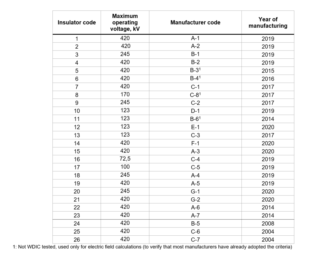
Table 1 - Summary of insulators used for electric field calculations and testing
3.2. Electric field calculations
The electric field calculations were performed for all insulators equipped with arcing horns/grading rings recommended by manufacturers or purchased by power utilities together with the insulators (detailed drawings were also provided), as intended in service. All calculations were performed in Comsol Multiphysics 5.5 software [18]. The insulator strings were fitted in a “standard” tower model most typical for each utility, see several examples in Figure 5.
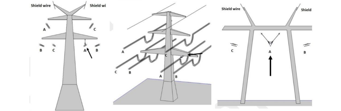
Figure 5 - Examples of different 400 kV “typical” tower models for the specific power company used for comparative calculations of electric field and positions of investigated insulators marked by arrows (corresponding in each case to the phase with the highest electric field stress).
To simulate a worst-case scenario from an electric field point of view, the 3D electric field calculations were performed for the phase having the highest electric field stress. Only six to eight sheds (or shed pairs in case of the alternating profile) at the HV end of the insulator were normally modelled. This simplification is based on I2G’s earlier experience with similar calculations, where it was shown that only a few sheds close to the insulator fittings are exposed to the highest electric field stress [2]. Such simplification does not influence the results but reduces drastic time for calculations. The potentials of phase conductors and connected metal hardware were set to values corresponding to the maximum system voltage. The potential of the tower structure, ground surface, insulator upper (grounded) end fitting, and shield wires, were set to zero. If the arcing horn/grading ring arrangement was not symmetric, the electric field stress was evaluated on both sides of the insulator and the highest values were conservatively used. The permittivity values used for the insulating materials were as follows: air – 1; housing – 3 (for both silicone types, HTV and LSR); glass fiber core – 5. The chosen values are “typical” based on many years’ experiences and are applied to all types of silicone rubber insulators.
In general, the calculations covered the following:
- the absolute electric field stress on the arcing horn/grading ring,
- the tangential electric field stress along the insulator housing surface at the HV end,
- the tangential electric field stress at the triple point.
Typical results of calculations are presented for the illustration in Figure 6.
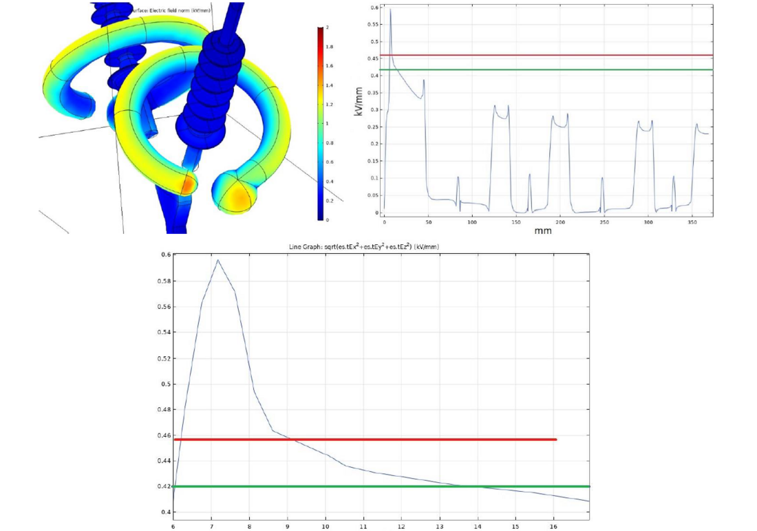
Figure 6 - Examples of typical results obtained by electric field calculations for two different insulators (left-right). Top-left: normal electric field stress at grading ring/arcing horn, colour scale 0-2 kV/mm (from blue to red). Top-right: tangential electric field stress along the housing used for the calculation of average along 10 mm. Scale on y-axis 0-0,6 kV/mm. Bottom: close-up on top right image. Average electric field stress along 10 mm (red line) compared with the criterion 0,42 kV/mm (green line), scale on y-axis 0,4-0,6 kV/mm
The results of the calculations are summarized in Table 2 using traffic light principles (GREEN colour illustrates the results below the criterion and RED colour illustrates the results above the criterion). For Emax values averaged along any 10 mm of housing surface, the results which are very close to the criterion of 0,42 kV/mm, are illustrated by YELLOW colour. The results of the electric field calculations allow to assume that all manufacturers are well aware about the proposed and internationally disseminated criteria, despite that they are not yet prescribed by IEC. This is because only 12% of the investigated insulators need small adjustments of the position of grading rings to avoid water drop induced corona (normally 2-10 cm up), and only 4% of the insulators (1 of 26) has too high electric field stress at the triple point. The excessive electric field values noted on metal parts (grading rings and fittings) are of second order importance in our case, because for all investigated insulators possible corona from these parts will be oriented away from the insulating body of the insulator.
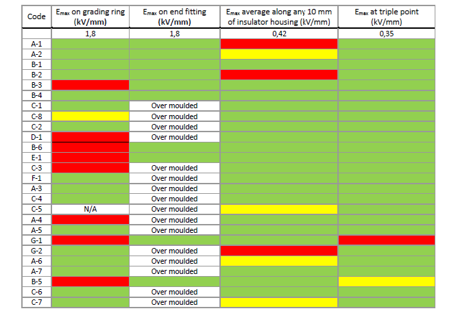
Table 2 - Summary of results of electric field calculations
Applying the proposed criteria for the limitation of electric field stress, no grading devices are needed for distribution class insulators (defined as < 110 kV). For transmission class insulators, one grading ring at the HV fitting is normally needed from 110 kV and up to 170 kV and two grading rings (at both ends) are required starting typically from 220 kV. These estimations based on calculations are confirmed by the answers to the specialized questionnaire distributed within this project, see Figure 7. The answers to the questionnaire received from 50 utilities cover the experience with about 9 million overhead line composite insulators installed at transmission and distribution voltage levels. These insulators are estimated to represent about 25% of all installations of line composite insulators worldwide with the average time in service 24 years (with a maximum of 40 years) [19]. One of the questions was if power utilities are using grading/corona rings and if they do, at which voltage levels.
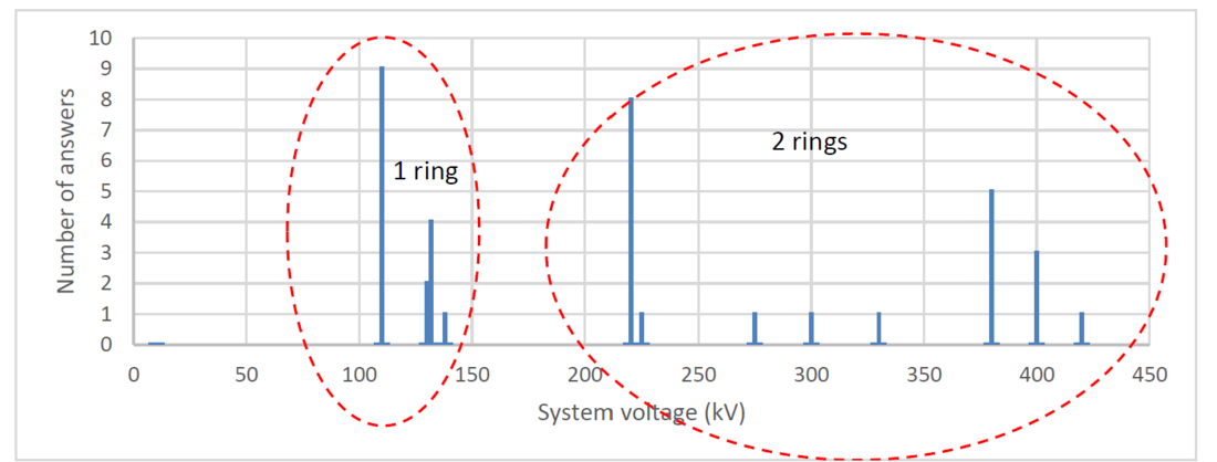
Figure 7 - Application of grading rings depending on voltage level (the results from the special questionnaire distributed for power utilities). The Y-axis shows the number of answers related to the specific voltage level
3.3. Water drop induced corona (WDIC) test
Test method:
The test set-up and the test environment (minimum 45% humidity) were as per the RIV-test (IEC 60437), with a simulated tower making the test arrangement equivalent to service conditions. An example of the set-up is presented in Figure 8.
The wetting of the bottom part of the insulators was done by using the spray bottle recommended for the wettability test according to IEC 62073, from a distance of approximately 25 cm and lasting approximately 5 s, until the distribution of water drops was saturated. All metallic parts were then properly dried with a piece of paper/cloth to make sure that no water drop corona from metal would mask the main test result, i.e., corona on housing. The conductivity of the water was as for standard IEC rain, i.e., 100 μS/cm. The test voltage was applied in the same way as for the corona test (IEC 61284), i.e., the voltage was first increased to the corona inception voltage (or, if reached first, 120% of maximum operating voltage) and then reduced to a target voltage of 100% of the maximum operating voltage. Observation of visible corona was done at these two voltage levels, with the voltage kept for 60 seconds at each level to allow for proper documentation using still image cameras.
The observation of corona was made by two standard photo cameras (Nikon D70), installed in parallel, and using 30 seconds exposure time. One camera was placed on a tripod on the floor and the other in the sky-lift at a height slightly above the bottom of grading ring. It is important to document the results by photographs taken from above and below the sensitive area of the test object since the corona activity could otherwise be hidden from one of the directions.
The criterion was absence of visible corona at 100% of maximum operating voltage. Examples of detected corona are presented in Figure 9 and Figure 10 and are directly compared with the corresponding results of electric field calculations.
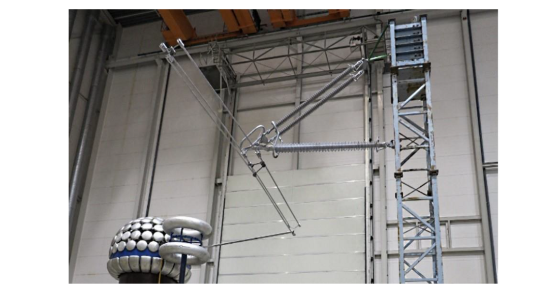
Figure 8 - Example of set-up for the WDIC test for the cross-arm arrangement with simulation of both conductor bundle and tower
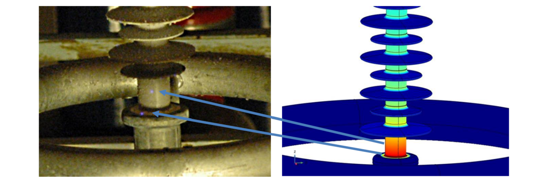
Figure 9 - First example of typical results obtained in the WDIC test. Left: visible corona in the test; right: clear indication to get visible corona in a sensitive area close to and at the sealing (respective maximum electric field >0,42 kV/mm)
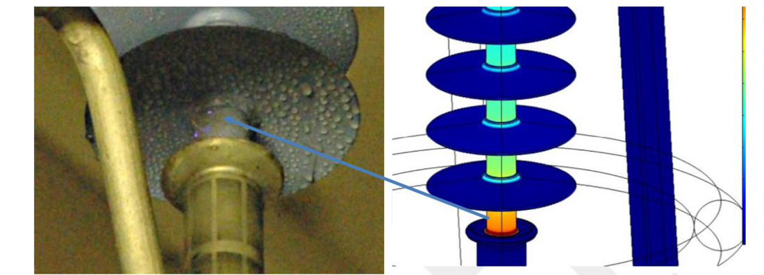
Figure 10 - Second example of typical results obtained in the WDIC test. Left: visible corona in the test; right: indication to get visible corona (respective maximum electric field >0,42 kV/mm)
Test results
The results of the WDIC tests are summarized in Table 3. A Red-Yellow-Green traffic light rating system is again applied, i.e., GREEN colour illustrates insulators which PASSED, YELLOW colour illustrates borderline cases (valid only for electric field calculations), and RED colour illustrates that an insulator DID NOT PASS the test. The results of tests are compared with electric field calculations.
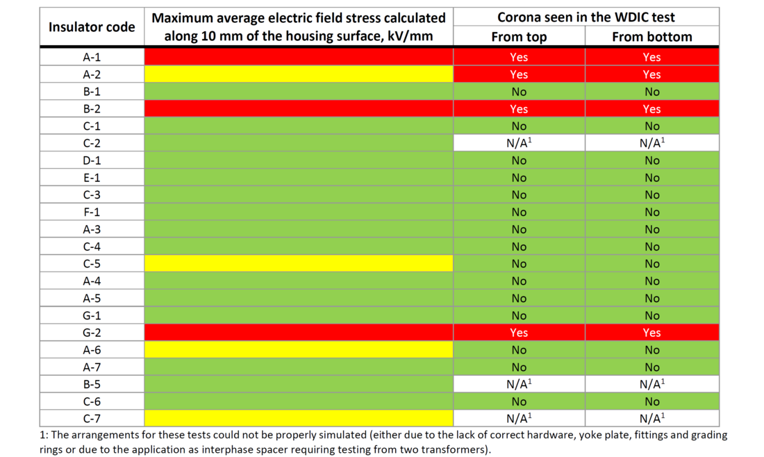
Table 3 - Summary of results of WDIC tests
A summary of the test results in comparison with the calculations is very promising (considering note below Table 3):
- For calculated values above the criterion of 0,42 kV/mm three out of three electric field calculations were confirmed by the test, i.e., 100%.
- For calculated values below 0,42 kV/mm all fifteen electric field calculations were verified by the test (no corona), i.e., 100%.
- For calculated values very close to the criterion of 0,42 kV/mm (within 5%), three out of four electric field calculations were confirmed by the test, i.e., 75%. In this specific case, however, it might be complicated to be sure about the visibility of corona.
4. Conclusion
The obtained results showed that the earlier proposed, internationally-disseminated and recognized criteria for the limitation of the electric field in sensitive areas of overhead line composite insulators, work well. This was verified for the comprehensive array of twenty-six commercial insulators from the storages of participating utilities (26 to be calculated and 22 to be tested). The results of electric field calculations are also well supported by the results of the Water Drop Induced Corona (WDIC) test. At present, these criteria are under discussion in two IEC maintenance teams revising the IEC 62217 and IEC 61109. For IEC 62217, it has already been decided to include a general description of the electric field requirements, leaving the criteria to the product standards. These criteria are already included in several utilities' technical specifications worldwide and it is high time to finalize their standardization in relevant IEC standards.
The WDIC test complies with IEC requirements for a new test and became mature via Round Robin Test in different laboratories. The comparison of test results with the calculations showed the results are 100% confident with the proposed criteria and 75% confident in borderline cases very close to the criteria. This test will be included in CIGRE technical brochure prepared by WG B2.57. This test can be easily performed after the standard RIV test (using the same set-up) and may also be included in technical specifications of utilities as a complement for electric field calculations.
References
- A.J. Philips, A.J. Maxwell, C.S. Engelbrecht, I. Gutman: “Electric Field Limits for the Design of Grading Rings for Composite Line Insulators”, IEEE Transactions on Power Delivery, Vol. 30, No. 3, June 2015, p.p. 1110-1118
- I. Gutman, P. Sidenvall: “Optimal Dimensioning of Corona/Grading Rings for Composite Insulators: Calculations & Verification by Testing”, World Congress & Exhibition on Insulators, Arresters & Bushings, Munich, Germany, 18-21 October 2015
- IEC Standard: “Radio interference test on high-voltage insulators”, IEC 60437 Second Edition, 1997-09
- IEC Standard: “Overhead lines - Requirements and tests for fittings”, IEC 61284 Second Edition, 1997-09
- P. Sidenvall, N. Sundin, I. Gutman, L. Carlshem, R. Kleveborn: “Development of test method to verify composite insulators from water induced corona point of view”, 32nd Electrical Insulation Conference (EIC), Philadelphia, Pennsylvania, USA, 8 -11 June 2014, paper S11-3
- P. Sidenvall, I. Gutman, L. Carlshem, J. Bartsch, R. Kleveborn: “Development of the Water Drop Induced Corona WDIC Test Method for Composite Insulators”, IEEE Electrical Insulation Magazine, November/December 2015, Vol. 31, No. 6, p.p. 43-51
- I. Gutman, A. Dernfalk: “Innovative testing techniques for verification of corona, pollution and ice/snow performance of insulation structures”, World Congress & Exhibition on Insulators, Arresters & Bushings, Barcelona-Sitges, Spain, 5-8 November 2017
- P. Sidenvall, I. Gutman, L. Carlshem, J. Bartsch: “A Round Robin Test of the Water Induced Corona Test”, ICOLIM-2017, Strasbourg, France, 26-28 April 2017, paper 0017
- CIGRE WG B2.03: “Use of corona rings to control the electrical field along transmission line composite insulators”, Brochure 284, December 2005
- A.J. Phillips, J. Kuffel, A. Baker, J. Burnham, A. Carreira, E. Cherney, W. Chisholm, M. Farzaneh, R. Gemignani, A. Gillespie, T. Grisham, R. Hill, T. Saha, B. Vancia, J. Yu: “Electric Fields on AC Composite Transmission Line Insulators”, IEEE Transactions on Power Delivery, Vol. 23, No. 2, April 2008, p.p. 823-830
- I. Gutman, J. Lundquist, V. Dubickas, L. Carlshem, R. Kleveborn: “Design of corona/arcing rings when replacing cap-and-pin insulators by composite insulators”, 17th ISH-2011, Hannover, Germany, 22-26 August, 2011, A-007
- P. Sidenvall, I. Gutman, J. Schulte-Fischedick, J. Seifert, J-F. Goffinet: “Methodology of Modern E-field Calculations - Case Study for Insulated Cross-Arm”, CEIDP-2013, p.p. 334-337
- M. Radosavljevic, I. Gutman, C. Ahlholm, P. Sidenvall: “Ageing and deterioration of composite post insulators exposed to high electric field in 220 kV and 400 kV switchyards in Swedish network”, 2017 CIGRE SC B3 Colloquium, Recife, Brazil, 18-20 September 2017
- P. Sidenvall, I. Gutman, J.-F. Goffinet: “Application of new test procedure for verification of water drop corona on innovative insulation cross-arms”, 19th ISH-2015, Pilsen, Czech Republic, 23-28 August, 2015, paper 262
- I. Gutman, J. Lundengård, S. Bucan, P. Sidenvall, J.-F. Goffinet: “Trends in pollution/corona testing for compact insulation systems in the form of insulated cross-arms”, CIGRE SC D1 Colloquium, Rio de Janeiro, Brazil, 13-18th September 2015, paper 12
- IEC 62217: “Polymeric HV insulators for indoor and outdoor use - General definitions, test methods and acceptance criteria”, Ed. 2.0, 2012-09 (under revision)
- IEC 61109: “Insulators for overhead lines – composite suspension and tension insulators for a.c. systems with a nominal voltage greater than 1 000 V – Definitions, test methods and acceptance criteria”, Ed. 2.0, 2008-05 (under revision)
- Comsol Multiphysics® 5.5, 2020, www.comsol.com.
- I. Gutman, A. Deckwerth, K. Halsan, M. Leonhardsberger, P. Meyer, L. Diaz, M. Radosavljevic, P. Trenz, K. Varli, K. Välimaa: “Application of Composite Insulators: Perceptions vs. Service Experience”, 2022 INMR World Congress, Berlin, Germany, 16-19 October 2022 (accepted for the publication)