Low-cost Ultrafast Modular HVDC Circuit Breaker
Authors
S. NEE, T. MODEER, L. ANGQUIST, S. NORRGA - SCiBreak AB

Summary
The vast majority of HVDC installations so far are of the point-to-point type, which connects two points in an AC grid, or two AC grids, by a DC link. As HVDC becomes more prevalent, it will be highly beneficial to start interconnecting HVDC links on the DC side into multiterminal systems, and eventually, to form HVDC grids. This reduces the number of needed converter stations radically, making HVDC more cost-effective, as highly expensive converters are avoided. Also, power losses are reduced. However, multiterminal HVDC requires access to reliable and fast DC circuit breakers for fault clearing. The VSC-assisted resonant current (VARC) technology, pioneered by SCiBreak, can combine these features at acceptable cost. Furthermore, VARC efficiently lends itself to modularization, whereby a breaker is assembled from a number of identical series-connected breaker modules. This brings two important benefits. First, scalability in terms of voltage at minimum engineering effort is obtained. Second, fault tolerance can be achieved by adding one or more redundant breaker modules. In case one of the modules fail to operate, the remaining modules can still interrupt the fault current.
Given the criticality of HVDC equipment for the electrical energy system, type testing of components is of paramount importance. KEMA Labs in Arnhem, Netherlands have set up an infrastructure in line with the latest standardization activities for HVDC breaker testing, that uses low-frequency short-circuit generators to provide fault currents similar to those in HVDC.
An 80 kV modular VARC-based breaker using three submodules with 12 kA interruption capability has been developed and manufactured. It has been tested under various realistic circumstances at KEMA Labs. It was found that it could interrupt a fault current of 12 kA with 1.5 ms neutralization time and 15 kA with 2 ms neutralization time. By neutralization time is meant the delay from the order to interrupt is given until the fault current starts decreasing.
Keywords
HVDC - HVDC Circuit Breaker - Multiterminal HVDC - vacuum interrupter1. Introduction
The transition to a decarbonized electricity supply system calls for increased use of HVDC power transmission. The best sites for renewable energy sources are often located far from consumers. Often long cables need to be used, for instance in the case of offshore wind power, and here the HVDC is the only choice since AC cables cannot feasibly be made longer than approx. 100 km. Also, the variable nature of renewables, such and wind and solar power, makes more long-distance transmission necessary, so that the variability can be balanced out over a larger area.
As HVDC links become more prevalent it will become favorable to connect them into multiterminal connections, that may eventually evolve into a DC grid. This can save investment cost, since the number of costly converter stations can be reduced. In addition, security of supply is improved since power can be routed in alternative paths in case of a converter fault, for instance. However, in order for this to be possible HVDC circuit breakers (CBs) need to be available as a mature technology at feasible cost. Development efforts to this end have been made since the 1970s. Recent endeavors include the hybrid HVDC CB[2]. It is based on using a mechanical contact (an ultra-fast disconnector, UFD) for conducting the current in the normal case, whereas power semiconductors are used for interruption. While this concept has been shown to work well in lab tests, it is rather costly, as the power semiconductors need to be dimensioned for both the full returning voltage and the full fault current. To reduce cost, a mechanical breaking element, such as a vacuum interrupter (VI) can be used instead. However, it needs a zero-crossing in the current to stop conducting and start blocking voltage. Zero crossings are normally present in any AC circuit, but to interrupt DC an artificial zero crossing must be provided. An LC resonant circuit connected in parallel with the VI, where the capacitor is initially charged to high voltage, can be used to provide a current pulse that cancels out the line current through the VI. A type of DC breaker that relies on this solution is the active current injection HVDC CB [3]. It can be manufactured at reasonable cost, but interruption is comparatively slow and takes 2−8 ms. Furthermore, it requires specialized vacuum interrupters, and a fast high-voltage switch to block the capacitor voltage in the normal case.
In [4] a new class of DC CBs was first presented. It also uses a resonant circuit, but in this case it is excited by a small voltage source converter (VSC). Hence it is named VSC assisted resonant current (VARC™) breaker. It offers several benefits. Cost can be kept low as the power electronics only need to be rated for a fraction of the voltage handled by the breaker. High–speed operation is possible with proven operating times of below 2 ms. In addition, this type of breaker can be manufactured using mostly standard, off-the-shelf, components.
In high-voltage applications modular equipment designs, where combinations of many submodules are used to handle high voltage and power provide several benefits. Scalability and fault tolerance can be achieved. Notably, the modular multilevel converter [6] has completely taken over the market for VSC HVDC converters during the last 15 years. The VARC concept can also be modularized, using a number of submodules each of them being able to block a fraction of the system voltage. This paper describes the design and testing of such a modular VARC HVDC circuit breaker.
2. HVDC grids and the need for DC circuit breakers
The vast majority of HVDC systems installed to date are of the point-to-point, or back-to-back types, where two points in the same AC grid, or two different AC grids, are connected by a DC link. Interconnecting HVDC links on the DC side into multiterminal connections is a crucial path towards reducing costs and increasing reliability, see Figure 1. These could eventually evolve into an HVDC grid. The benefits of DC-side interconnection are that the number of expensive converter stations can be radically reduced, lowering investment costs. Furthermore, with point-to-point connections, power passing from one DC feeder to another will be subject to around 2 % losses in the converters during conversion to AC and back to DC. This is avoided with the direct DC interconnection, leading to further reductions in lifecycle costs.
HVDC grids of any considerable complexity will require DC circuit breakers to clear faults. A DC short- circuit fault propagates rapidly, meaning that it needs to be cleared in few milliseconds to avoid having to block the converters, which would mean disrupted transmission in the grid. In addition, in a DC circuit the peak fault current is not limited by the network impedance, only the current rate of rise, implying that the DC CB has to limit the fault current before it rises to a level that is harmful for equipment in the grid. If a sufficiently fast HVDC breaker cannot be provided, the only option is to connect series inductance, but that causes additional cost and power losses. A further requirement on HVDC circuit breakers is that cost must not be excessive. Since the purpose of developing HVDC grids is to save investment cost it is obvious that the cost of the breaker cannot approach that of a converter station, even though it is clear that a DC breaker will be considerably more expensive than an AC breaker of similar rating.
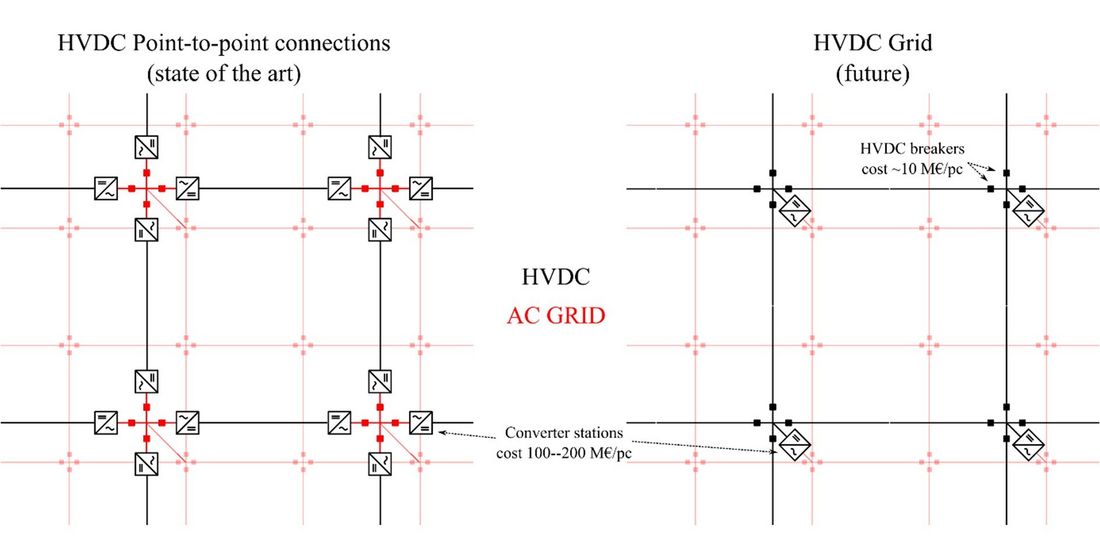
Figure 1 - Comparison of HVDC point-to-point connections (left), and an HVDC grid with HVDC circuit breakers (right)
3. Modular VARCS HVDC circuit breaker
The VARC concept for lends itself well to designing scalable HVDC circuit breakers by series connecting a variable number of modules of lower voltage capability.
3.1. Current interruption principle
The main circuit of a VARC circuit breaker, and the principal voltage and current waveforms during a current interruption are shown in Figure 2. The line current is conducted by metallic contacts in a vacuum interrupter (VI) during normal, closed, conditions. Thereby, the losses are kept low, and complex cooling systems are not needed. Furthermore, the contact system has high current carrying capability when closed. The vacuum interrupter has good current interruption capability at current zero- crossings and can withstand both high voltage and high voltage-derivative following current extinction. However, an artificial current zero cross-over in the VI current is required for current extinction. To provide it, a current injection branch, consisting of a capacitor C, an inductor L and a small voltage source converter (VSC), is connected in parallel with the main VI. During an interruption, contact opening by an ultrafast actuator is first initiated. When the contact separation is sufficient, the VSC is controlled to produce a high-frequency square-wave voltage, UVSC, which results in an oscillating current with increasing magnitude IRES in the injection branch. This current soon approaches the line current IS in magnitude. Since the resonant circuit also comprises the VI, this implies a zero crossing in the current through the VI, upon which the VI interrupts.
Inductance exists in all power systems, which means that the line current cannot immediately be brought down to zero. Instead, an alternative path must be provided for the current when the interruption through the VI is executed. The new current path shall cause a high, preferably constant, opposing voltage that exceeds the source voltage in the system, thereby forcing line current down to zero. Metal oxide varistors (MOV), possess that property, and are widely used for voltage limiting in power systems. An MOV is connected across the interrupter terminals, and its clamping voltage is in this context called the transient interruption voltage (TIV), see [1]. It is selected to be approximately 50% higher than the system DC voltage. The MOV also serves the purpose of limiting the voltage across the vacuum interrupter to a level it can withstand.
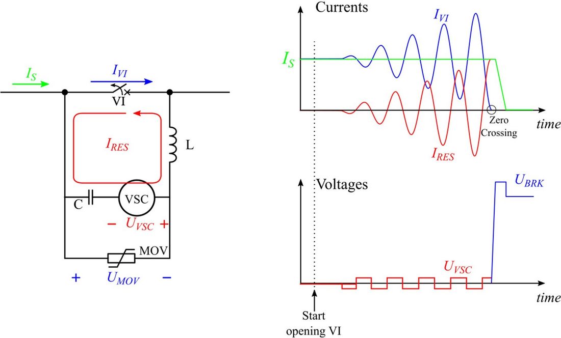
Figure 2 - VARC DC CB concept: main circuit (left), indicative waveforms (right)
3.2. Breaker Submodule Implementation
The modular HVDC breaker is assembled from submodules rated at 40 kV TIV. This voltage is determined by the clamping voltage of the surge arrester stack connected in parallel with the VI. Since the surge arrester is connected nearly in parallel with the module terminals, the minimum clearances within the module are determined in accordance with the module surge arrester voltage level, rather than the system voltage level. The module, see Figure 4, is divided into a low voltage compartment and an open-frame high voltage part. The low voltage compartment houses the VSC, the control system and the charging circuits. The module design is based on a welded steel frame, to provide enough strength for stacking. During the breaker operating time, 1.5 ms, the VI contacts needs to be separated several millimeters. Such rapid movement is achieved using a Thomson coil actuator, as shown in Figure 3. In addition to a fast opening time, the actuator mechanism also needs to maintain sufficient contact pressure in the closed state, to keep the contact resistance low and the peak current withstand capability sufficiently high.
An FPGA-based control system controls the VSC, the VI, and the charging circuits in the module, as well as to maintain communication with other modules and the substation controller. The VSC control requires fast sampling with low propagation delay, both to be able to accurately switch the VSC during the resonant current excitation and to be able to quickly detect when the module successfully has interrupted the current. The sampling period and sampling delay are therefore both less than a microsecond. All components used in the breaker module are commercial off-the-shelf, which lowers the cost. The modules are designed to be stackable, with a maximum number of six modules in a stack.
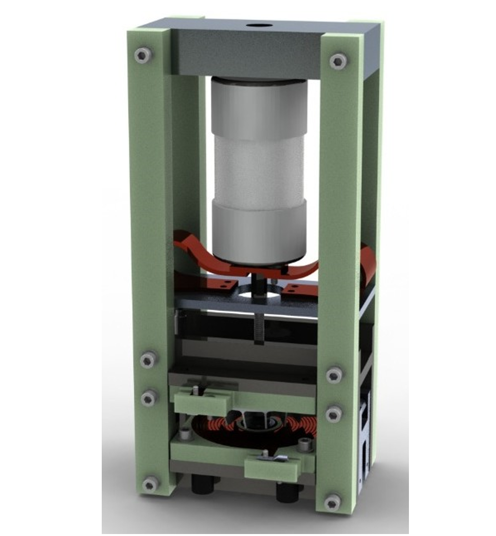
Figure 3 - Vacuum interrupter (top) with mounted Thomson coil actuator (bottom)
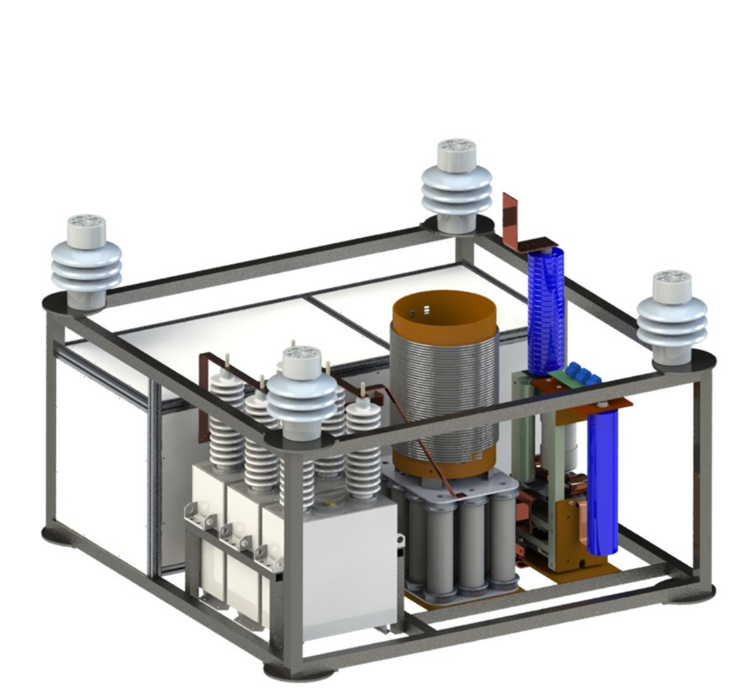
Figure 4 - Breaker submodule. The footprint is
1.4 m × 1.4 m. Each added module adds 1 m to the height of the stack
3.3. Complete Modular HVDC CB with Series-connected Submodules
A suitable number of modules are connected in series to form a full circuit breaker. These modules all work individually, and contain everything needed to contribute their part to the total breaker TIV during an interruption operation. At least one of the modules works as a central control, that relays signals from the substation to each of the modules in the string. All modules are capable of acting as a central control module, and can do so if connected with optical fibers to the substation control system. Information about module status, measurement values from transducers connected to any one module et cetera, can be shared freely among the modules and the substation controller. To prevent restrikes after interruption, and ensure even stressing of the MOVs, it is important that the voltage is shared evenly between all modules. On a time scale of milliseconds, voltage (and power) is evenly shared between the modules through the robust clamping of the MOVs in each module. On a very short time scale, voltage is shared between the modules using small snubbers connected across the vacuum interrupters of each module. In this way, the energy and voltage can be shared evenly under all operating conditions [8]. Large variations in energy dissipation between the modules can only occur as a consequence of failure of a module to make or break. The circuit breaker can be made tolerant to such a failure in one or more of the modules, by a slight increase of the MOV rating. As an example, the energy dissipation per module in a 320 kV circuit breaker is around 30% higher if one module fails to operate than it is if all modules operate [7].
Like other types of DC circuit breakers, VARC requires auxiliary power. The standby auxiliary power need of each breaker module is, however, very low, in the range 10-20 W. The auxiliary power system is dimensioned primarily by requirements on the breaker recharge time, i.e. the time for the breaker to be ready for a repeated rapid open-close-open sequence. Auxiliary power supply of 300 W to each module results in a recharge time of 90 seconds, after which an open-close-open cycle can be performed in quick succession again. If a longer recharge time is acceptable, the auxiliary power supply per module can be reduced down to just above the standby power requirements.
A prototype HVDC CB consisting of three modules (Figure 5), fully demonstrating the operation of a modular circuit breaker, was designed, built, and tested as part of the PROMOTioN project. This circuit breaker was designed for operation at 80 kV, with a TIV of 120 kV. For the targeted 80 kV system voltage, high voltage isolation transformers operating at 50 Hz were chosen for the auxiliary power supply. The main ratings of this circuit breaker are compiled in Table 1.
A VARC circuit breaker for 320 kV could in straight-forward manner be constructed by adding more modules of the same type, connecting them together and mounting corona shields to attachment points on the module frames, see Figure 6. In addition to inherent redundancy, a modular design allows for simplified testing, since nearly all functionality can be verified through the testing of a single module. Since only one module design is required, less effort is also required for component procurement than if the breaker needed be redesigned for every voltage level.
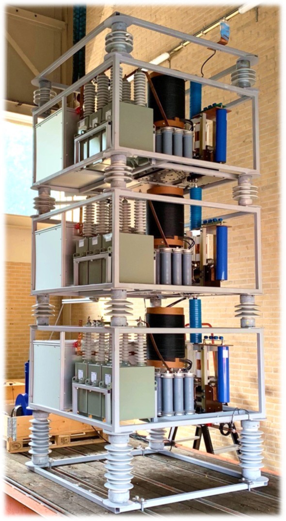
Figure 5 - 80 kV modular HVDC breaker
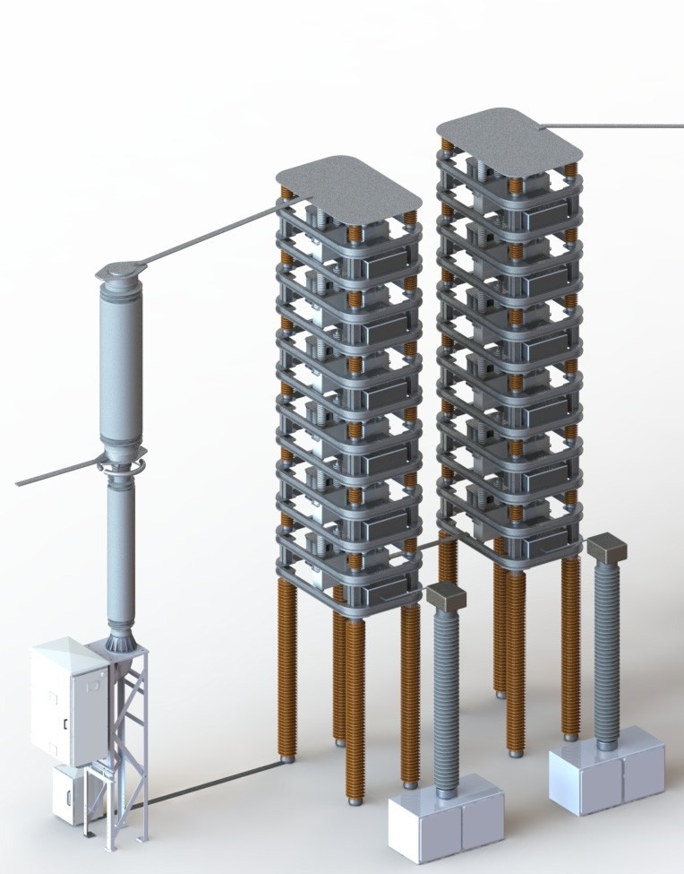
Figure 6 - Rendering of a 320 kV HVDC breaker
with residual current switch
| Parameter | Value |
|---|---|
| Rated DC voltage | 80 kV |
| Rated DC current | 2000 A |
| Rated maximum fault current | 12 kA |
| Minimum operating time | 1.5 ms |
| Maximum dissipated energy | 2.5 MJ |
4. Testing of the modular HVDC breaker
4.1. Laboratory facilities used
For the initial in-house testing of the modular HVDC breaker a simplified test circuit based on the capacitor discharge was used [9]. KEMA laboratories have made great efforts at developing an infrastructure for realistic testing of HVDC circuit breakers. Based on analyses of realistic fault cases in HVDC grids the proper test requirements have been identified [10]. Accordingly, test facilities have been set up using low-frequency short-circuit generators [12] to mimic the short-circuit transients in HVDC systems. These were employed for the test of the modular HVDC breaker.
4.2. Results
Short-circuit test were carried out at various current levels, as summarized by Table 2 below. Representative waveforms from a fault current interruption test (TF100) are shown in . The tests TC100 and TF100 represent load current switching and fault current interruption, respectively. The test TF100* at 15 kA shows the maximum breaking capacity of the breaker. TF100, the rated maximum fault current breaking test, was initially performed according to specification, with 2 ms operation time, and then again with 1.5 ms operation time to demonstrate the capability of the breaker. The test TC10 illustrates low-current switching and the TDT test illustrates interruption with long subsequent suppression time and high energy dissipation. All tests except TF100* were made at both current directions without changes to the circuit breaker or its settings.
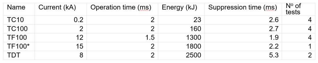
Table 2 - Overview of tests performed on circuit breaker at KEMA laboratories in August 2020. All tests except TF100* were split into different current directions, so e.g. TF100 was performed with two tests at 12 kA and two tests at –12 kA
5. Conclusion
A full-scale modular HVDC circuit breaker of the VARC type has been designed and tested. The tests conform that the circuit breaker allows for a neutralization speed of 1.5 ms at 12 kA interrupted current, and a maximum interruptible current of 15 kA. It is thus proven that the modularization of the VARC concept works under realistic HVDC fault conditions. The modular design, provides scalability, so that any multiple of 40 kV can be chosen as the TIV of the circuit breaker. Furthermore, the design enables fault tolerance through redundancy, as well as a reduction in component cost and testing.
In summary: fast, inexpensive, scalable, and fault-tolerant HVDC circuit breakers are now ready for deployment.
Acknowledgments
The work described in this paper was made possible thanks to support of InnoEnergy Scandinavia, Svenska Kraftnät and the Swedish Energy Agency.
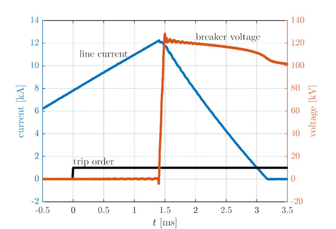
Figure 7 - Test results from KEMA when switching 12 kA against 120 kV returning voltage test
This work was supported by the European Union’s Horizon 2020 research and innovation program under grant No.691714.
References
- CIGRE Technical Brochure 683 “Technical Requirements and Specifications of State-Of-The-Art HVDC Switching Equipment” (Joined Working Group A3/B4.34, April 2017).
- Häfner J., Jacobson B.: Proactive hybrid HVDC-breakers – A key innovation for reliable HVDC grid, Cigré symposium, Bologna, Italy, 2011.
- Tokoyoda S., Tahata K., Kamei K., Kikuchi K., Yoshida D., Oukaili S., Yamamoto R., Ito H.: DC circuit breakers for HVDC grid applications – HVDC and power electronics technology and developments, CIGRE LUND 2015, paper 135
- Ängquist L., Norrga S., Modeer T.: A new dc breaker with reduced need for semiconductors, EPE’16 ECCE Europe, Karlsruhe, Germany, 2016.
- L. Ängquist, S. Nee, T. Modéer, A. Baudoin, S. Norrga, N. A. Belda ”Design and test of VSC assisted resonant current (VARC) DC circuit breaker” (15th IET Internation al Conference on AC and DC Power Transmission (ACDC 2019), 5-7 Feb. 2019, Coventry, UK).
- A. Lesnicar and R. Marquardt, “An innovative modular multilevel converter topology suitable for a wide power range,” in 2003 IEEE Bologna Power Tech Conference Proceedings,, vol. 3, 2003.
- M. Poikilidis, R. Smeets, N. Belda, S. Nee, S. Mebrahtu-Melake, T. Inagaki, "Document on failure mode analysis of HVDC circuit breakers", deliverable 10.5 of the EU Horizon 2020 project PROMOTioN, 2020.
- S. Liu et al., "Modeling, Experimental Validation, and Application of VARC HVDC Circuit Breakers," in IEEE Transactions on Power Delivery, vol. 35, no. 3, pp. 1515-1526, June 2020.
- S. Nee, T. Modeer, L. Ängquist, S. Norrga and A. Baudoin, "Tank test circuit for fast DC circuit-breakers," 15th IET International Conference on AC and DC Power Transmission (ACDC 2019), Coventry, UK, 2019.
- N. A. Belda, C. A. Plet and R. P. P. Smeets, "Analysis of Faults in Multiterminal HVDC Grid for Definition of Test Requirements of HVDC Circuit Breakers," in IEEE Transactions on Power Delivery, vol. 33, no. 1, pp. 403-411, Feb. 2018.
- N. A. Belda and R. P. P. Smeets, "Test Circuits for HVDC Circuit Breakers," in IEEE Transactions on Power Delivery, vol. 32, no. 1, pp. 285-293, Feb. 2017.
- N. A. Belda, C. A. Plet and R. P. P. Smeets, "Full-Power Test of HVDC Circuit-Breakers With AC Short- Circuit Generators Operated at Low Power Frequency," in IEEE Transactions on Power Delivery, vol. 34, no. 5, pp. 1843-1852, Oct. 2019.