Mitigation measures for increasing penetration of solar Photovoltaic (PV) systems in Distribution networks
Authors
A. PANDARUM - Eskom Holdings SOC Ltd South Africa

Summary
South Africa is currently experiencing an increasing growth in installation of embedded solar PV installations on the distribution grid. This is driven by a reduction in installation and component costs coupled with increasing tariffs resulting in an attractive financial business case for customers who wish to reduce their electricity bill. However, this poses a wide range of technical challenges for Network Service Providers (NSPs). The conventional design of the distribution grid, whereby unidirectional power flows from the generation source to the loads no longer exists. Moreover, the lack of visibility of these installations makes it more challenging for the development of planning and operational strategies. As it is the responsibility of the NSP to maintain power quality, safety and network reliability/stability for their customers, it is essential that the consequences and potential cost implications brought about by increasing penetration of such installations on the distribution networks is understood. This paper discusses some of the significant impacts resulting from increasing penetration of solar PV on distribution grids, mitigation measures for these impacts as well as possible cost implications for the utility/NSP. Furthermore, recommendations are provided for planning of future networks with increasing PV penetrations in South Africa.
Keywords
PV penetration - Voltage rise - Network asset congestion - Mitigation measures1. Introduction
From past research reports, it is evident that there is an increasing penetration of small scale embedded generation (SSEG) being installed on the electrical grid of South Africa. This is mainly due to decreasing installation costs as well as increasing tariffs resulting in an attractive financial business case for customers who wish to reduce their electricity bills. However, as it may seem appetizing to the customer, Network Service Providers (NSP) are not being made aware of the installations nor are their grids ready or designed for these systems. Furthermore, as per the national Grid Codes, it is the responsibility of the NSP to maintain power quality, safety and network reliability and stability for their customers. It is therefore essential that NSP’s understand the consequences and potential cost implications for increasing penetration of SSEG’s on the distribution networks.
The technical challenges that were previously identified and can be associated with high and undesirable SSEG penetration levels are:
- Power flow fluctuations,
- Increased technical losses,
- Overloading of equipment installed on the grid such as Medium Voltage (MV)/Low Voltage (LV) transformers and cables,
- Grid protection malfunction and
- Voltage variation, unbalance and overvoltage.
The primary challenges of increasing penetration is generally related to the impact on voltage i.e. overvoltage and voltage variations. These are also considered to be the limiting factors for increasing penetration on MV/LV grids as most research suggests.
[1] details the results for potential technical impacts of increasing penetration of PV in distribution networks in South Africa. The work completed in this report highlighted the differences in impact of installing increasing penetrations of PV on a constrained and unconstrained network. The main findings of the report was as follows:
- The most significant impact stems from installing PV only at the end of the networks for both case studies,
- Overvoltage, voltage rise and rapid voltage changes/voltage variations are experienced when installing PV. These impacts are increased as the PV penetration increases and can have detrimental effects to the equipment that is currently installed on the network,
- Technical losses are decreased when installing PV on the constrained network for all penetrations below 75% of peak load. However, for the unconstrained network, the losses already start to increase by 40% penetration,
- Equipment loading starts to worsen after 30% penetration for the constrained network and worsens for any PV penetration in the unconstrained network and
- The acceptable hosting capacity based on voltage and thermal loading impacts was ~15% and ~30% of peak load for the constrained and unconstrained network, respectively. This occurs in the case where the systems are only installed at the end of the network. Furthermore, the voltage impacts on the constrained feeder seems to be worse than for the unconstrained feeder.
Following the results from the case studies, this research aims provide insight into the network management methods that can be adopted to overcome/alleviate voltage and asset congestion impacts experienced when increasing PV penetration in distribution networks.
2. Technical solutions and mitigation measures
This section provides details about the solutions that can be implemented to mitigate technical impacts of increasing penetration of PV on Distribution networks and to further increase hosting capacity on a network. Many measures have been mentioned in research however; there is a lack of comprehensive analysis of advantages and disadvantages of them [2]. These methods are tabulated in Table 1, where some advantages and disadvantages are mentioned, furthermore, the placement or responsible party is also highlighted [2, 3, 4, 5]. The advantages and disadvantages of each measure is classified in terms of mitigating or managing voltage violations or asset congestion issues caused by increasing PV on Distribution networks. These methods have been assessed on various types of networks theoretically using simulation tools.
The mitigation measures with associated locations are illustrated in Figure 1 below.
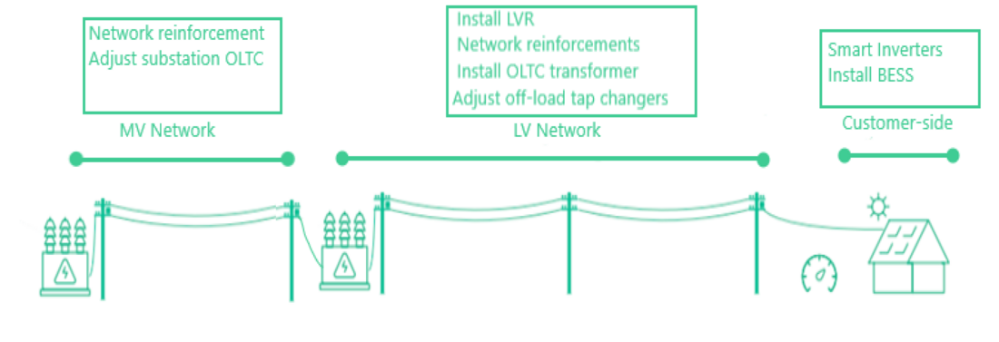
Figure 1 - Mitigation measures with associated locations
Details about some mitigation measures from Table 1 and its implementation is discussed below. It must be noted that the technical solutions provided in the table are, to a large extent, able to manage voltage violations; however, they are not always able to effectively manage asset congestion issues. As such, [5] has propose a combination of solutions, which will also be detailed in Section 2.10 below.
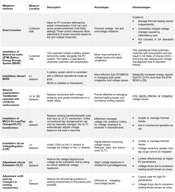
Table 1 - Summary of technical solutions and mitigation measures for increasing PV on Distribution networks [2, 3, 4, 5, 6]
2.1. Smart inverters
Conventional grid-tied inverters allowed for the installation of SSEG’s in the South African grid are generally controlled to feed the maximum power available from the resource (solar, wind, etc.) and disconnect from the grid during abnormal conditions or power outages. However, as more of these systems are being connected to distribution grids around the world, international utilities are calling for these inverters to support grid in an active manner [7]. This is apparent in the latest IEEE Standard 1547 for Interconnection and Interoperability of Distributed Energy Resources with Associated Electric Power Systems Interfaces (2018); distribution grid codes such as Hawaiian Electric Rule 14H and California Rule 21, and inverter standards such as AS/NZS 4777.2:2015 require the inverter based SSEG’s to provide control functions. These controls can be autonomously and/or via smart grid communications. The definition of these types of smart inverters can such that they are capable of offering the following five system functions [8]: i) integrated sensing and measurement functions, ii) integrated system control functions (e.g. grid-forming and regulation capabilities), iii) integrated system protection functions, iv) distributed system stabilization functions (e.g. virtual inertia and damping provisions) and v) integrated cybersecurity functions.
The mitigation measure recommended here makes use of function i) mentioned above to utilise tailored internal inverter control settings to amend the output power (either active or reactive) of the PV system. The manner in which this is implemented internationally is dependent on the inverter and utility codes for embedded generation. The active power settings, referred to as Volt-Watt, entails the reduction of active power as a function of the grid voltage metered by the inverter. Similarly, the reactive power settings, referred to as Volt-Var, entails the compensation of reactive power also as a function of the metered grid voltage. A visual example of the implementation of these settings is illustrated in Figure 2 below.
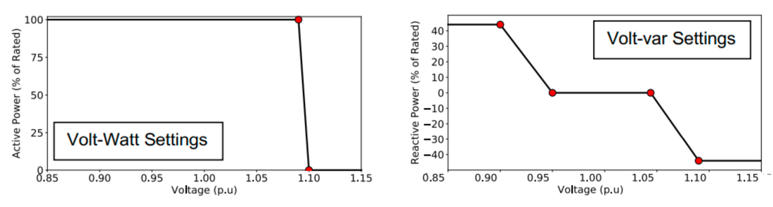
Figure 2 - Example of tailored Volt-Watt and Volt-Var inverter settings [5]
One of the major advantages to this solution is that it does not require any financial input from the utility. Furthermore, studies have proven that this solution is highly effective at managing voltage violations, regardless of the type of network.
2.2. Installation of Behind-the-meter Battery Energy Storage System (BESS)
This solution requires the installation of behind-the-meter BESS alongside the PV system which set to the operation mode that maximises self-consumption. This means when PV generation exceeds customers demand, the BESS charges using the excess PV generation and when PV generation falls below the customers demand, the BESS discharges to meet the demand. However, studies [2, 8] show that with this operation mode, the typical residential sized BESS can reach State-of-Charge (SOC) during the day due to the systems not being adequately discharged. For that reason, the effectiveness of managing the voltage and asset congestion issues on the network is reduced, especially in comparison to the other mitigation measures.
2.3. Adjustment of Off-load Tap Changers in existing transformers
This is a simple approach to creating voltage headroom in an MV network. It involves manually decreasing the tap positions of all existing MV/LV transformers to the lowest possible point so that additional headroom is created for more export of PV generation until voltage violations are reached. [9] showed that this solution can create ~5% more headroom when all taps on a network is reduced as seen in Figure 3. The main disadvantage of this solution is that it does not assist with asset congestion in any way. Furthermore, voltage drops due to excessive loading conditions at peak periods can become problematic. Therefore, it is recommended that detailed network studies be completed prior to implementation, especially for networks in South Africa, which are known to be severely loaded.
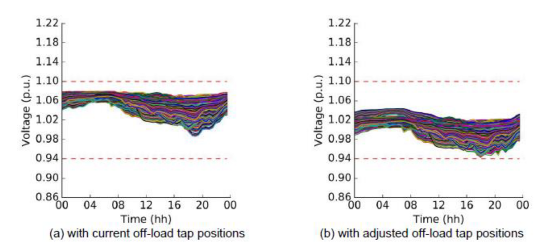
Figure 3 - Change in customer voltage that is created when adjusting all the off-load tap positions of MV/LV transformers on a network [5]
2.4. Installation of Low Voltage Regulator (LVR)
This solution considers the installation of a LVR or Step Voltage Regulator (SVR) at an optimal location along the LV network. The study [2] modelled the Pacific Volt LVR- 30 device (30kVA on single phase and 90kVA on three phase) which can regulate the LV voltage by 13%, at most. The optimal location suggested by [2] was just after the MV/LV transformer in a location that results in a step-down in voltages due to the load of the customers on the network. This works better for urban LV networks rather than rural networks. Unfortunately, asset congestion issues will not be solved using this solution. Furthermore, LVR’s are not in full commercial operation yet.
2.5. Network Augmentation (MV & LV) – Transformer upgrades and conductor reinforcement
This solution involves the uprating of existing MV/LV transformers to ones with the largest possible rating as well as the replacement of existing high impedance MV and LV conductors to that with larger ampacity. This can be implemented for the conductor/s along the main and most problematic path as a more cost effective option. This concept is illustrated in Figure 4.
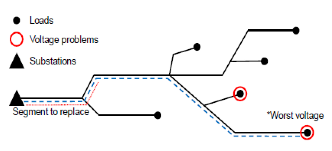
Figure 4 - Network augmentation for LV feeder (substations is the same as MV/LV transformer point)
The LV and MV conductors that could be considered for this option is tabulated in Table 2 and Table 3, respectively.
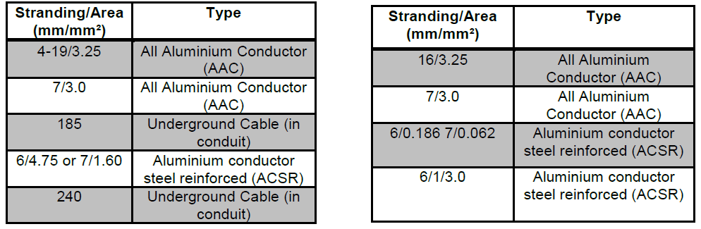
Table 2 (left) - LV conductors to consider for
augmentation of LV network [2, 4] / Table 3 (right) - MV conductors to consider for augmentation of MV network [4]
When uprating the MV/LV transformers the upgrade of transformers with two additional tap positions of 2.5% tap size can be considered [2].
2.6. Adjustment of Zone Substation OLTC
This solution involves reducing the target voltage of the HV/MV transformer at the zone substation to create additional headroom for voltage rise during high export of PV power. The results are similar to the option described in Section 2.3 and can be used in combination with it.
2.7. Installation of MV/LV On Load Tap Changer (OLTC) transformers
This solution considers the replacement of existing MV/LV off-load tap changer transformers to OLTC transformers. This changes the voltage management from a passive exercise to more of an active one that occurs closer to the load. OLTCs typically exist on the primary side of the MV/LV transformer and are controlled by a device called the Automatic Voltage Control (AVC) relay. This AVC relay uses voltage measurements taken from the secondary side (Vs in figure below) of the transformer to determine the tap change requirements and inherently the voltage regulation. There is a delay in sending the signal for the tap change to avoid excessive tap changes stemming from possible short period voltage deviations. This typical voltage control logic is illustrated in Figure 5.
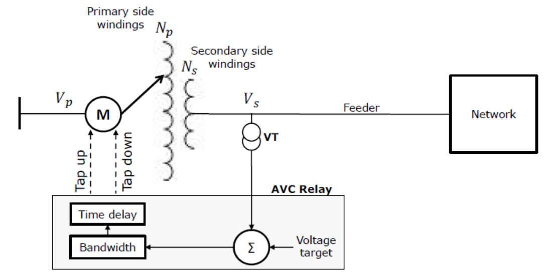
Figure 5 - Voltage control logic of OLTCs in transformers [8]
Study [8] has indicated that the typical operation of the OLTC as mentioned above may not be the most suitable as the target voltage is fixed and this may result in the voltage violations at the far end of the LV network. This is especially true for uneven loads and generation from new technologies such as PV which may cause excessive wear and tear on the tap changers. It was therefore recommended that an adaptive control mechanism be considered when implementing this solution. This includes which leveraging smart meter load data to actively calculate the target voltage.
OLTCs are not currently available for transformers below a certain rating [2]. However, [5] indicated that it is possible to retrofit an existing transformer by adding the active voltage control OLTC capability to it. The ones that were considered in the studies reviewed had ±8-10% total voltage regulation capability [2, 5, 4, 10]. This option provides mitigation for voltage issues caused by increasing PV, however, asset congestion issues still remain a concern.
2.8. Combination solutions [4]
No one solution is able to address both voltage issues and asset congestions issues effectively, as seen above by the advantages and disadvantages of each mitigation measure. Most of the solutions do mitigate voltage issues and only network augmentation is seen to address asset congestion problems but not voltage issues. Consequently, [4] suggested that different combinations of solutions be evaluated to identify the most effective and economical solution at tackling both voltage and asset congestion issues with increasing PV on the distribution network. The combination solutions evaluated were:
- Smart inverters + network augmentation + adjustment of off-load tap changers,
- Adjustment of off-load tap changers + smart inverters + adjustment of zone Substation OLTC,
- Smart inverters with tailored Volt-Watt and Volt-Var settings + network augmentation + adjustment of off-load tap changers,
- Installation of MV/LV OLTC transformers + network augmentation + adjustment of off-load tap changers + smart inverters,
- Installation of behind-the-meter BESS + network augmentation + adjustment of off-load tap changers + smart inverters,
- Installation of network BESS + network augmentation + adjustment of off-load tap changers + smart inverters,
- Network augmentation + adjustment of off-load tap changers + smart inverters + dynamic target voltage at Zone Substation.
All the combination solutions were modelled for i) Long Rural (LR) – 692km total length (incl. 194km Single Wire Earth Return (SWER) conductor),ii) Short Rural (SR) – 329km total length (incl. 54km SWER conductor), iii) Long Urban (LU) – 70km total length (no SWER) and iv) Short Urban (SU) – 30km total length (no SWER); all 22kV with pseudo LV networks. The results showed that combination solution 3, 4 and 6 works for all networks and can allow 100% PV penetration without any violations. No other solutions worked at increasing the PV penetration on the long rural network, however; option 1, 2 and 5 worked for the short rural and the long urban network until 20% and 40% PV penetration.
3. Conclusion
Various measures to mitigate/alleviate the technical impacts of increasing PV penetration on MV and LV networks have been unpacked in this report. It is evident that no one solution is effective at solving the major issues brought about by increasing PV penetration on distribution networks. The mitigation measures need to be considered in conjunction with the PV penetration limits desired. It is important to note that adjusting regulations for inverters, such as implementing requirements with tailored Volt-Watt and Volt-Var settings, can allow for improved quality of supply without any costs to the NSP/utility. The results from the studies reviewed showed that with the implementation of smart inverters of these tailored settings, PV penetration of up to 35% can be allowed in some distribution networks. However, other impacts of high reactive power compensation on existing equipment must be considered and fully understood prior to this change in regulation.
There are different solutions for different types of networks. There seems to be more effective measures that exist for urban networks rather than rural networks. Study [5] has shown that the solutions for rural networks are also much more expensive for the same desired PV penetration level.
Network reinforcement and OLTC transformers are considered to have the highest net- benefit for higher PV penetrations (>60%). The network reinforcement option also seems to be the most effective at resolving asset congestion issues; whereas the OLTC transformers options is most effective at resolving voltage issues.
It must be understood that the “do-nothing” option can significantly decrease the life of existing plant and inadvertently cost the utility more money in the long run. There is no doubt that increasing PV penetration leads to increasing grid voltage, thermal loading and technical losses. These impacts cause network equipment to “run hotter” and effectively reduce their mean-time to failure. Further noting that NSP’s have not been able to perform pro-active maintenance of equipment due to financial constraints.
South Africa does not currently have the aspiration of increasing PV penetration at the distribution level due to concerns around asset congestion and voltage issues experienced when doing so. However, it must be noted that these issues may already be experienced with existing penetrations due to lack of visibility of installations as well as poorly managed networks. In those cases, the mitigations measures from this report can be explored as solutions. Furthermore, when South Africa does begin to explore higher PV penetrations, the recommendations and mitigation measures detailed in this report, along with applicable simulations, should be considered.
4. Recommendations
The following recommendations are proposed for a successful future utility with increasing penetration of PV on the distribution grid [2, 4]:
- It is imperative that the inverter standards, specifically NRS 097-2-1, are updated to ensure visibility on the LV network as well as promote smart inverters with dynamic Volt-Watt and Volt-Var control.
- Upgrade MV/LV transformers with additional buck taps in the off-load tap changer during replacement activities.
- Increase visibility on the LV networks, especially those that are starting to experience increases in PV penetration. A start would be to install smart meters at critical points on the LV networks to obtain data and to create LV network drawings and power flow models for network planners to use in their studies. This is predominantly for future planning activities as well as for the transition into the field of evaluating LV hosting capacity. Currently, the LV network has been seen as a low priority for utilities but PV has changed this notion for international Distribution Network Service Providers (DNSPs).
- Consider and model other complementary mitigation measures such as the combination solutions presented above. It was evident from the studies that no one solution can assist with all the technical impacts introduced by increasing PV penetration on the network.
- Explore other operational modes for battery systems. The studies showed that operation behind-the-meter BESS in self consumption mode did not really mitigate the voltage issues on the network. Smarter solutions need to be developed and implemented. This can also be informed by regulation and incentives can be given to those who implement smarter batteries for the utility’s benefit.
- Consider demand control measures to alleviate the impacts of increasing PV on the network. This could include active control of large loads in customer premises in a smart way.
- Consider the impact that Electric Vehicles (EVs) may have on the overall impact in the future grid with increased penetration of PV.
References
- A. Pandarum, “Impact of Increasing Distributed Solar PV Systems on Distribution Networks in South Africa,” International Journal of Energy and Power Engineering, vol. 15, no. 1, pp. 47-53, 2020.
- S. Hashemi and J. Østergaard, “Methods and strategies for overvoltage prevention in low voltage distribution systems with PV,” IET Renewable Power Generation, vol. 11, no. 2, pp. 205-214, 2016.
- ENEA Consulting, “Future grid for distributed energy,” ENEA Consulting, 2020.
- D. Cheng, M. Mather, R. Seguin, R. Robert Broadwater and J. Hambrick, “Photovoltaic (PV) Impact Assessment for Very High Penetration Levels,” IEEE Journal of Photovoltaics, 2016.
- W. Nacmanson and L. Ochao, “Advanced Planning of PV-Rich Distribution Networks - Deliverable 5: Cost Comparison Among Potential Solutions,” The University of Melbourne, 2020.
- K. Kotsalos, I. Miranda, J. Dominguez-Garcia, H. Leite, N. Silva and N. Hatziargyriou, “Exploiting OLTC and BESS Operation Coordinated with Active Network Management in LV Networks,” MDPI, 2020.
- S. Xu, Y. Xue and L. Chang, “Review of Power System Support Functions for Inverter-Based Distributed Energy Resources Standards, Control Algorithms, and Trends,” IEEE open journal of Power electronics, vol. 2, 2021.
- Y. Xue, M. Starke, J. Dong, M. Olama, T. Kuruganti, J. Taft and M. Shankar, “On a future for smart inverters with integrated system functions,” 9th IEEE International Symposium on Power Electronics for Distributed Generation Systems (PEDG), 2018 .
- A. Procopiou, M. Liu, W. Nacmanson and L. Ochoa, “Advanced Planning of PV- Rich Distribution Networks – Deliverable 4: Non-Traditional Solutions,” The University of Melbourne, 2020.
- A. Procopiou, K. Petrou and L. Ochoa, “Advanced Planning of PV-Rich Distribution Networks Deliverable 3: Traditional Solutions,” The University of Melbourne, 2020.
- A. Navarro-Espinosa and L. Ochoa, “Increasing the PV Hosting Capacity of LV Networks: OLTC-Fitted Transformers vs. Reinforcements,” IEEE, 2015.