Virtual Synchronous Generator Versus Synchronous Condensers: An Electromagnetic Transient Simulation-based Comparison
Authors
S. HADAVI, S. PHU ME, B. BAHRANI - Department of Electrical and Computer Systems Engineering, Monash University, Australia
M. FARD - Aurecon Australia Pty, Australia
A. ZADEH - Array Technologies Inc.

Summary
Due to the observation of new stability challenges in the high penetration of renewable energy resources in weak grids, there is a need for assets to stabilize power systems. Synchronous Condensers (SynCons) are a well-known technology as a system strength remediation. However, SynCons capital cost is a drawback for their operation. Virtual Synchronous Generators (VSGs) are a new technology that can mimic synchronous machines behaviour. Therefore, there is a need to investigate and compare SynCons and VSGs performance in weak grid integration of renewable energy resources. This paper investigates VSG's performance in weak grid integration of a solar farm in a single machine infinite bus (SMIB) system. The VSG performance is compared to a SMIB case with the utilization of a SynCon. PSCAD/EMTDC is selected for time-domain analysis of the SMIB case, and all system equipment is modelled in detail. Different Australian grid code tests are applied to the SMIB system to evaluate the VSG and SynCon's impact. The simulation results show that the VSG performs better than SynCon in the weak grid system and improves stability.
Keywords
Weak grid - Virtual Synchronous Generator - Synchronous Condenser - Network Stability - Australian Grid Code - Grid Following - Grid Forming1. Introduction
In the recent decade, increasing global warming and technological development in harvesting renewable energies were sufficient to motivate almost every developed and developing country to set a renewable energy target within 10-20 years. As a result, increasing renewable energy installed capacity in power system networks has become a global trend. Although the definition of renewable energy sources can be applied to a broad range of technologies (e.g., Hydro, Geothermal, and Biomass), generating electricity from wind and solar can easily account for the most predominant technologies installed worldwide, which are mainly connected via power electronic converters. Thus, renewable energy sources can address global warming concerns and provide environmentally friendly electricity for areas away from power transmission infrastructure. However, they also introduce new challenges to power system networks. Increasing the number of grid-connected renewable energy is often referred to as renewable energy penetration, theoretically a positive factor. However, it can become a technical challenge when the ratio of installed traditional power plants (e.g., synchronous generators) to renewable energy sources (such as solar farms) steadily declines.
Historically, most existing power system networks consist of synchronous generators (such as hydropower plants and steam power plants). In power systems, network strength and system stability are defined based on the ability of the system to maintain the voltage in the system [1].
Nowadays, there are countless financial and environmental incentives to increase renewable energy penetration in power system networks and replace conventional synchronous generators with inverter-based technologies. As this trend gains further attention, the mechanical rotary mass ratio to inverter technologies drops into a smaller value. Hence, the power system network is continuously experiencing a reduction in system inertia. A power system with low inertia is prone to higher frequency volatility, which can become quickly unstable, mainly after contingency events. Low inertia results in faster voltage, frequency, and angular instability in any power system, making it hard to avoid system blackouts and interruption in the power supply [1].
In addition to inertia, synchronous generators can provide fault current contribution of nearly 300-400% of their nominal rating; however, grid-connected inverters used in solar farms have relatively much lower fault contribution capability. A combination of lower fault contribution and reduced inertia causes power system networks to experience a low short-circuit ratio (SCR) at the point of connection of grid-connected generators. The lower SCR shows a higher voltage sensitivity to changes in active and reactive powers import and export [2, 3]. It is worth mentioning that not all renewable energy sources are relaying in inverter-based technologies. However, with significant land accessibility and immense sun irradiation in a country like Australia, generating electricity from solar farms can be the most dominant means. As solar farms implement inverter-based technology without rotating mass, a power system network like Australia can significantly suffer from a deficit of inertia in the network while its solar farm penetration rises.
From generators prospect, establishing and maintaining a stable connection to a network with a low SCR and low inertia imposes several operational issues that limit any generator's range of stable operation. Inverter-based generators, such as solar farms, which are normally grid following type, require rigorous tuning of their control loops to provide stable operation whenever connected to a low strength network due to their inherent fast response characteristic. If the stable operation cannot be achieved by tuning the control loops, output curtailment should be adopted to lower plant output. Furthermore, during contingency events that can cause a significant voltage drop at the inverter terminals, these solar farms may not meet grid support requirements due to existing voltage sensitivity within the grid.
To avoid curtailing maximum power extraction from solar farms in low strength networks, one or a combination of fast-acting solutions such as Static VAR Compensators (SVCs), Static Synchronous Compensators (STATCOMs), Synchronous Condensers (SynCon), and grid-forming inverters (GFMI) with synthetic inertia capability (virtual synchronous generator) should be considered as an additive to those plants. Generally, the Virtual Synchronous Generator (VSG) can provide additional features that can generate revenue if the ancillary market is available apart from increasing network stability; in contrast, the former solutions can only provide reactive power support.
This paper analyzes and compares two leading solutions, synchronous condenser and virtual synchronous generator (VSG). Each solution's impact is investigated on an actual Australian network scenario when a solar farm is connected to a low system strength network. To compare a SynCon performance and a VSG performance in a weak grid, different test scenarios are applied on a SMIB case with the SynCon and the VSG. The test scenarios are selected based on the Australian grid code. The tests include the large-signal tests, such as fault ride-through capability and small-signal tests, such as voltage reference step change. The SMIB case is considered as a very weak grid, which the solar farm cannot operate stably without any system remediation techniques. Finally, the simulation is done in PSCAD/EMTDC software to evaluate the VSG and SynCon performance.
The rest of this paper is organized as follows. In Section 2, an explanation of current challenges and solutions for the high penetration of renewable resources is presented. Section 3 describes two common assets for system strength remediation and summarizes their advantages and drawbacks. In Section 4, the performance of a VSG in a weak grid is investigated and compared to a SynCon performance under different tests. Finally, conclusions derived through the results of this study are presented in Section 5.
2. Weak grid stability issues and grid code requirements
Recently, the high penetration of Inverter Based Resources (IBRs) and the retirement of old fossil fuel-based generators have introduced new power systems challenges. The majority of IBRs are located in remote areas which are connected via long transmission lines. The long transmission lines have high impedance, decreasing the short circuit capacity and SCR at the connection point. A power system with an SCR of less than three is considered a weak grid. Weak grid integration of IBRs can cause unstable operation of RERs in a system [4, 5].
Furthermore, IBRs, typically operate in a grid-following mode. In the grid-following mode, the IBRs follow the angle and voltage from the point of connection and inject active and reactive power according to their setpoints. In the grid-following mode, the IBRs are using PLLs to operate stably. However, in weak grids, PLLs may cause instability in the IBRs operation. Increasing the number of IBRs and their interaction with grid elements introduce new challenges in power systems. Sub-Synchronous Resonance (SSR) linked with weak grid-connected IBRs has attracted significant attention in recent years. In 2009, the first SSR related to IBRs was observed in ERCOT [6], Texas. The interaction of a wind farm with series capacitors causes the SSR in the system. SSR is caused by Sub-Synchronous Oscillations (SSOs) in the system. In North China, SSOs have been observed because of type 4 wind farms and the weak grid [7]. Also, South Australia experienced a blackout in 2016, which cascaded wind farms' failure due to multiple contingencies that caused the blackout. Eight wind farms protection systems tripped them after six voltage dips. Thus, the South Australian system faced a generation reduction of 456 megawatts (MW) in less than seven seconds [8].
To avoid the mentioned power systems challenges, power system operators in different countries introduce standards and grid codes. All IBRs that want to connect to the grid must follow these grid codes. Australia is one of the pioneers in the IBRs connection, and the Australian power grid has several weak grid points to which IBRs are connected. Therefore, the Australian grid code includes more comprehensive and strict rules among its counterparts [9, 10]. The National Electricity Rules (NER), the Australian grid code, has a complete chapter for connecting a new generation to the grid, such as IBRs [11].
Moreover, there are different reactive current injection requirements during voltage dip or reactive current absorption for high voltage ride-through and specific voltage settling time for each IBR, challenging IBRs to comply with those rules. Also, IBRs interaction with other installed IBRs in weak grids can cause stability issues. Therefore, remediation assets to increase system strength such as SynCon and GFMI are required. In Section 3, the SynCons and VSGs are described briefly as remediation assets for IBRs operation in weak grids.
3. System strength remediation assets
3.1. Synchronous Condenser
A SynCon is a synchronous machine without a prime mover, considered a reborn technology to remediate system strength challenges. Since increasing the penetration of renewable energy decreases the inertia in power systems, SynCons can be one solution to provide inertia. Also, SynCons can regulate voltage by injecting and absorbing reactive power [4, 12]. In weak grids, voltage is sensitive to contingencies. Thus, voltage regulation is an advantage of SynCons in the operation of weak grids.
Additionally, the protection of power systems is a challenging topic, and it is not straightforward with the high penetration of renewable energy. As the number of IBRs increases, the conventional protection over-current scheme has become inadequate because traditional generators, including synchronous machines, have different fault characteristics and responses compared to IBRs. IBRs fault currents are primarily determined by their controllers. Generally, IBRs have a limited fault current in the range of 1.2 to 1.5pu of their nominal current, and the traditional generators can provide around six times their nominal current. Therefore, the conventional overcurrent protection schemes and relay are unreliable and challenging to coordinate with IBRs [13]. Consequently, they can help IBRs to comply with strict rules and ride through the contingencies.
SynCon has noticeable drawbacks, such as high investment costs and long lead-time. Furthermore, SynCons installation, maintenance, and operation cost make SynCons a costly solution for system strength remediation [14]. Also, if extra inertia via flywheel is necessary, the costs will be increased significantly. In addition, massive infrastructure and a huge rotor installation of SynCons take time. It can take at least one year to install one SynCon unit in a system [4]. Additionally, SynCons do not have control over inertia response, and it's a natural response of SynCons.
3.2. Virtual Synchronous Generator
Generally, a grid-forming inverter (GFMI) is a family of inverters that control the voltage and its frequency at the inverter terminal. As reflected in grid-forming terms, these inverters are capable of black start operation, forming and maintaining the grid through voltage and frequency regulation at their terminal. Unlike grid-following inverters, which track and lock their output voltage with the grid voltage, GFMI can operate in a standalone mode or self-synchronize its output voltage with an upstream grid by a power synchronization mechanism, such as the swing equation of synchronous generators. Hence, grid forming inverters require voltage and frequency setpoints, while grid-following inverters require active and reactive power setpoints.
GFMIs in their standard forms are designed to respond based on droop functions. Thus, standard GFMIs are unable to provide inertia. However, these GFMIs can be equipped with synchronous generators (SG's) swing equation to provide synthetic inertia, commonly referred to as virtual synchronous generators. Typically, GFMI can be categorized as droop-based GFMIs, VSGs, and virtual-oscillation-control-based GFMIs [15]. However, due to the popularity and diversity of VSG applications, this work focuses only on VSG and its impact on system strength.
VSG is a semiconductor-based power converter, which mimics the operation of a classical synchronous generator. It is designed to provide synchronous-machine-like features, such as grid voltage regulation, inertia contribution, and standalone operation [16]. In other words, despite lacking mechanical rotating mass, VSG exhibits the same characteristic and dynamic response of synchronous generator by means of capturing swing equation characteristics in its control system.
These features are not available in conventional grid-following inverters. Instead, VSGs' primary control is governed by the swing equation of SGs, shown in Figure 1 to achieve the dynamic response of a synchronous generator [17]. P0 and P are the active power setpoint and the measured active power at a VSG PoC. Dp and J are the damping coefficient and the inertia of a VSG, respectively. ω0 , ω, and θ are the frequency setpoint, the internal frequency, and the phase angle is used for the Park transformation of a VSG. Finally, s denotes the Laplace variable.
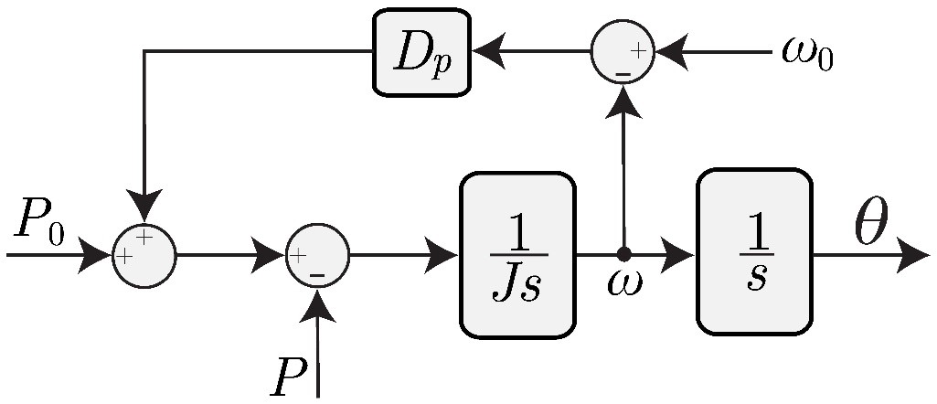
Figure 1 - The swing equation that governs the frequency control of the VSG
VSGs act as voltage-controlled sources in the power network and can increase inertia to the network [16]. Thanks to their voltage-controlled control technology, VSGs can be connected to an inverter-based resource (IBR) plant in weak grids to support terminal voltage, similarly to SynCons. The installation of VSGs in a renewable energy plant can be easily conducted by retrofitting several existing GFLIs with the VSG control, as that only requires firmware updates. Alternatively, larger VSGs with equipped battery energy storage systems (BESSs) can be installed in weak parts of a power system to support multiple IBRs in these areas [15]. The reactive power amount used for regulating the IBR plant's terminal voltage can be provided by VSGs' reactive power and voltage controls. Thanks to their voltage-controlled operation, VSGs can offer terminal voltage support to an IBR plant in weak grids by injecting/absorbing reactive power to/from the grid. Hence, excessive reactive power extraction from the IBR plant for voltage control in low strength networks can be avoided. Thus, the IBR plant has more headroom for active power control.
Moreover, VSGs have been theoretically proved to have a more robust response than the conventional grid-following STATCOMs in weak grids [18, 19]. In addition, it has been found that installations of VSG can enhance the grid strength viewed by nearby IBR plants [18]. This feature makes VSG become a candidate for improving weak grid stability challenges.
3.2.1. Advantages and Disadvantages of VSGs
This section presents VSGs' strengths and weaknesses in supporting a solar farm connected to a weak network. The advantages of VSGs can be summarized as follows.
-
The imbalance between demands and supplies in the power system might lead to frequency deviations. Active power injection/absorption, also known as primary reserve, is required from the plants to support the system frequency in these scenarios. VSG's installation in IBR plants extends the plant's active power absorbing or injecting capability due to the BESS attached to the VSGs' DC bus, which means the VSGs enable the plant to provide a more significant contribution to the frequency support [18]. However, this function is not available in a SynCon due to the lack of a prime mover, while it has already been up and running with the VSG control in several industrial projects [15]. Further researches and developments are required to enable the operations of SynCon with BESSs for the frequency support purpose.
-
Flexible damping factor and inertia settings, compared to SynCon, are essential for VSGs. Two crucial advantages of SynCons are inertia capability and post-contingency damping. In a SynCon, the inertia is provided by the rotating mass, while the damping factor is determined by the damper windings, which are physically integrated with the SynCons during its manufacturing process. Consequently, to change the post-contingency damping of the SynCons, a disconnection from the system is required. Moreover, much effort is needed to replace the rotating mass of the SynCons. Therefore, these two properties are almost non-adjustable in SynCons. On the other hand, as the synchronous machine model is implemented in the VSGs controlling program, most of the VSGs properties, including the damping factor, can be easily manipulated by modifying the corresponding parameters of the inverter's firmware [19]. Also, the inertia of a VSG can be adjusted by modifying the total capacity of BESS connected to the DC bus of the VSG [16]. In contrast, the inertia of SynCon, due to its rotating mass, is a fixed property.
A power system stabilizer (PSS) can be used to improve the damping of SynCons. However, it is mainly used for suppressing the oscillations via the excitation system. On the other hand, the inbuilt damping of the VSG can directly impact the frequency and the output voltage angle. Thus, apart from dampening post-contingency oscillations, the inbuilt damping factor can restrain the angle evolution during a fault and extend the critical fault clearing time [20, 21]. Therefore, more benefits will be brought by improving the inbuilt damping factor. -
Besides enabling frequency support service, a BESS also allows VSGs to contribute inertia to the grid during a frequency disturbance to reduce the resulting rate of change of frequency and improve the frequency nadir. This feature helps the grid tackle the frequency deviation at the beginning of the disturbance before the fast frequency response is in service. Unlike the frequency support services provided by GFLIs, the virtual inertial response of VSGs is instantaneous and not degraded by the frequency/rate of change of frequency (RoCoF) measurement delays thanks to the replication of the SG's swing equation. Furthermore, since VSGs start tackling the frequency deviation immediately after the disturbance, less energy is injected/absorbed to support the grid frequency. Therefore, VSGs' frequency support services are more efficient than those by GFLIs [22].
-
VSG is more robust in weak grids compared to grid-following solutions. Semiconductor-based grid-following solutions, such as STATCOMs, do not operate effectively in weak grids due to the degradation of the phase-locked loop (PLL) [23]. On the other hand, not relying on the PLL and operating as a voltage source allow VSGs to perform well in weak grids. The robustness of VSGs in weak girds has been proved in the literature [24]. Besides, adding grid-forming voltage source converters (VSCs, e.g., VSGs) to a network consisting of multiple PLL-based converters helps improve the whole network's small-signal and robust stability [24, 25]. This fact is revealed by means of the impedance-based analysis and the structured singular value methods [24, 25].
For VSGs disadvantage, only low over-current capability compared to SynCons can be considered. The over-current limitation is the thermal limits of the power electronic switches (IGBTs) inside VSGs. As a result, the VSGs' over-current capability is only 20%-40% of its rated current, which is much lower than the counterpart of a SynCon [21].
4. Performance evaluation and comparison between VSG and SynCon Near and far fault
This section conducts a case study on a solar farm (SF) connected to a weak grid. The case study is simulated in PSCAD/EMTDC because investigating the transient and the dynamic response of IBRs, VSGs, and SynCons must be done in a time domain-based simulation. Also, PSCAD/EMTDC is an accepted software for EMT simulation in Australia, and the IBRs manufacturer must model their models in PSCAD software and comply with the Australian grid code. Several tests, including fault ride-through (FRT), voltage disturbance, active power reference tracking, and frequency disturbance, are applied to investigate the system's behaviours in three different scenarios. In the first scenario, which is the base case, the SF is connected to a Single Machine Infinite Bus (SMIB) system without any supporting device. The SMIB model is a weak grid model with SCR below 3, which solar farms cannot operate stably. Optimizing the SF control parameters can be a solution to enhance the stability of the farm. However, changes in the network, e.g., faults, line trippings, might negatively impact the effectiveness of the optimal parameters. Hence, more robust solutions should be considered. The SG-like assets, i.e., SynCon and VSG, are possible candidates for improving the SF's stability. Thus, in the other two scenarios, the SF in the first scenario is supported by either a SynCon or a VSG connected to the SF's medium-voltage (MV) bus. As aforementioned, the VSG can be formed by retrofitting several existing GFLIs in the SF park with the VSG control. The topologies of the three scenarios are shown in Figure 2. The parameters of the solar, the SynCon, and the VSG are listed in Table I. The SF, the SynCon, and the VSG are modelled in detail in PSCAD/EMTDC. The SF and SynCon models in this study are OEM developed models that capture a full detail of an actual product.
The control diagram of the VSG can be found in Figure 3. P and Q in this figure are the active and reactive power measured at the terminal of the VSG. ig,abc and ic,abc are the grid-side current and the converter-side current of the LCL filter used in the VSG, respectively. vc is the voltage across the capacitor of the LCL filter. The PWM outputs drive the semiconductor switches inside the VSG. All control parameters of the VSG can be found in Appendix I.
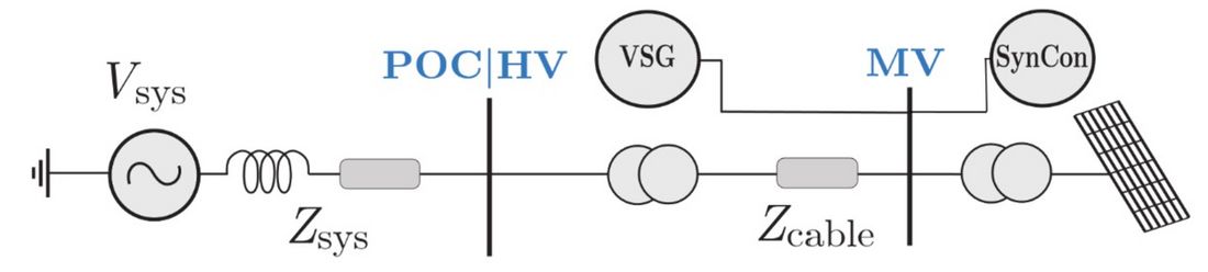
Figure 2 - Case study topology
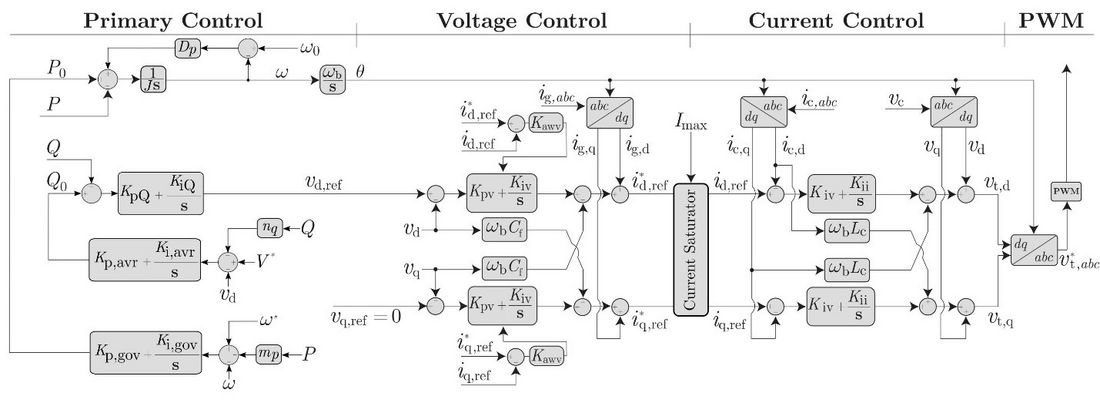
Figure 3 - Detailed control of the VSG
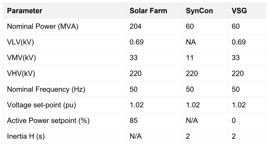
Table I - Test-bed system info
The simulation results of the tests in the test-bed SMIB are presented in the following subsections. The improvements brought by SynCons and GFMIs on enhancing the system strength and inertia are revealed. Performance comparisons of the remediation assets are also detailed below.
4.1. Fault-Ride-Through
Two tests are applied on the SMIB case to compare the enhancements brought by the SynCon and the VSG in terms of the FRT capability and the fault recovery. In the first test, a three-phase bolted fault, which is the most severe fault scenario, occurs at the SF's PoC and lasts for 120 ms. The responses of the system in the three scenarios are presented in Figure 3.
From Figure 3, the post-fault responses are significantly improved when either the SynCon or the VSG is connected to the PoC. Without these ancillary devices, long oscillatory transients in the PoC voltage, i.e., VPoC, the PoC active power, i.e. PPoC, and its reactive power, i.e., QPoC, persist for almost 1.6 s after the fault clearance. In addition, as shown in Figure 3(a), the spikes in VPoC exceeds 1.5 pu. These poor transients can trigger protection devices in the system, disconnecting the SF even though the fault is successfully cleared. These undesirable transients result from the voltage's extraordinary sensitivity to the variations in the current in weak grids [26, 27].
Moreover, these poorly damped transients in the post-fault voltage can trigger the SF's high-voltage ride-through (HVRT) function. This causes a mode cycling behaviour when the SF keeps entering and exiting the HVRT mode. The transitions between the normal operating mode and the HVRT mode of the inverters in the SF can contribute to the inadequate transient responses.
With the presence of the SynCon, VPoC, QPoC are quickly dampened and settle 0.17 s after the fault clearance, as shown in Figure 3(a). A voltage overshoot of 25% is recorded in this case, which shows a noticeable improvement compared to the base case. Moreover, thanks to the high overcurrent capability of the SynCon, a relatively high amount of reactive power is generated to support the grid during the fault, as shown in Figure 3(d). However, the SynCon results in the low-frequency oscillatory transient in the power responses presented in Figure 3(b) and Figure 3(e). The oscillation lasts for about 2 s after the fault clearance with the highest overshoot of 15 MW. The frequency of observed oscillation is around 1.6 Hz.
In the third scenario, the VSG is used for supporting the SF operation. The voltage and the power responses are well-damped by the VSG. All the responses settle within 0.17 s after the fault clearance. The overshoot and settling time of VPoC are very similar to those in the case where the SynCon is installed. Moreover, as depicted in Figures 3(b) and 3(e), no power oscillation is recorded when the VSG is installed. Because the frequency in Figure 3(f) rises above one pu after the fault clearance, the VSG absorbs an amount of active power to tackle the frequency deviation. As a result, the power responses are overshoot-free in this case, which shows a significant improvement compared to the case with the SynCon.
In general, compared to the base case, the highest voltage overshoot reduces by a factor of two and stably settles to the pre-fault condition with the presence of either the SynCon or the VSG. Besides, the power overshoot and settling time in the case with the VSG is only 1/6 and 1/12 of the counterparts in the case of the SynCon, respectively.
The SMIB case is tested with a shallower fault to validate the robustness of the VSG. In Figure 4, a fault occurs at 5 s and is cleared at 5.43 s, with a residual voltage of 0.5 pu. Similar to the previous case, without neither the SynCon nor the VSG, poor transients are recorded in VPoC, PPoC, and QPoC. The peak voltage oscillation reaches 1.6 pu, which can trigger protection devices, leading to a disconnection of the SF from the grid. Although the SynCon damps the voltage transient effectively, this device pollutes the power responses with subsynchronous oscillations, eventually damped after 1.3 s since the fault clearance. Finally, the VSG shows its effectiveness in enhancing both the voltage and the power responses. The voltage and power settle within 0.16 s with minimal oscillations and overshoots. In general, reductions of eight times and ten times are recorded in the settling time and the overshoot of the power response when replacing the SynCon with the VSG.
Overall, the VSG is superior in damping the poor post-fault transients, which the SF experiences in weak grids. Furthermore, compared to the SynCon, the VSG provides similar support in the voltage recovery while not generating the subsynchronous oscillations in the active power injected into the grid by the SynCon in transient processes. As a result, smooth recoveries are achieved in both the voltage and power responses using VSG.
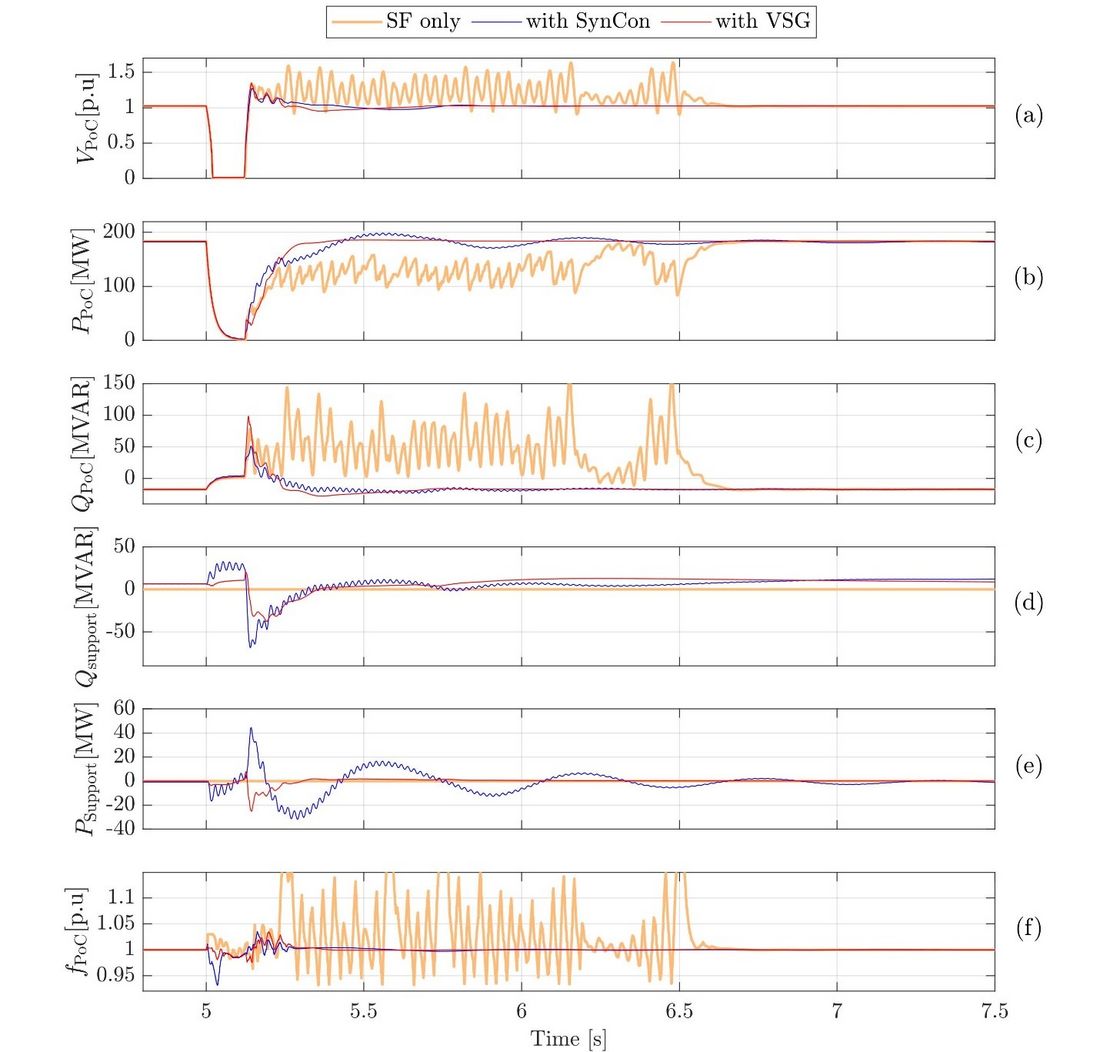
Figure 4 - The responses of the system to a three-phase bolted fault at the PoC: (a) the PoC voltage, (b) the active power transfer measured at the PoC, (c) the reactive power transfer measured at the PoC, (d) the reactive power contributed by the remediation asset, and (e) the active power contributed by the remediation, (f) the frequency at the PoC.
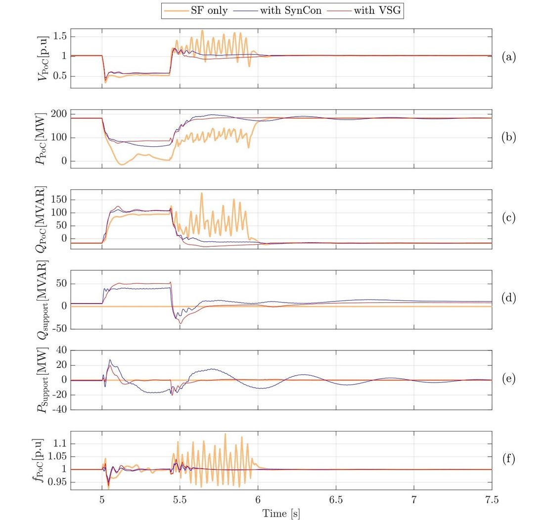
Figure 5 - The responses of the system to a three-phase fault at the PoC with 0.5 pu residual voltage during the fault: (a) the PoC voltage, (b) the active power transfer measured at the PoC, (c) the reactive power transfer measured at the PoC(d) the reactive power contributed by the remediation asset, and (e) the active power contributed by the remediation, (f) the frequency at the PoC..
4.2. Voltage Disturbance ( POC voltage change)
In this part, two voltage disturbance tests are conducted on the SMIB case to investigate the impacts and benefits of using the SynCon and the VSG in weak grids. The PoC voltage is either raised or decreased by 0.05 pu from the steady-state value in each test.
The test results are illustrated in Figure 5 and Figure 6. In Figure 5, at 5 s, a step fall is applied to the POC voltage. Right after the disturbance, the voltages in all three cases deviate from the reference. The lowest nadir is recorded in the case with the SF only. In contrast, the SynCon and the VSG in the other two cases increase their reactive powers, i.e., Qsupport, to tackle the disturbance resulting in shallower nadirs in these cases. Similar behaviours are observed with the rising voltage disturbance in Figure 6, where the SF's voltage deviation is restrained by the reactive power compensations provided by either the SynCon or the VSG.
Moreover, without the SynCon and the VSG, small oscillations persist for 0.7 s in VPoC, PPoC, and QPoC before the system's settlement. Although the SynCon and the VSG perform similarly in supporting the voltage, the SynCon injects low-frequency oscillation in the active power, whose magnitude and settling time are 5 MW and 2 s, respectively, to the grid as shown in Figure 5 and Figure 6. These oscillations are because of SynCon exciter interaction with the IBR controller [12]. Besides, the power responses of the SynCon are also polluted by high-frequency oscillations, whose frequency is 50 Hz. In contrast, the VSG's responses are oscillation-free. In conclusion, the VSG provides the SF with an optimal voltage disturbance rejection while enhancing the power responses' transients.
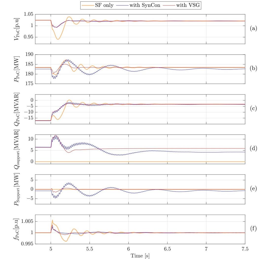
Figure 6 - The responses of the system to a step change from 1.0 pu to 0.95 pu in the PoC voltage: (a) the PoC voltage, (b) the active power transfer measured at the PoC, (c) the reactive power transfer measured at the PoC, (d) the reactive power contributed by the remediation asset, and (e) the active power contributed by the remediation , (f) the frequency at the PoC
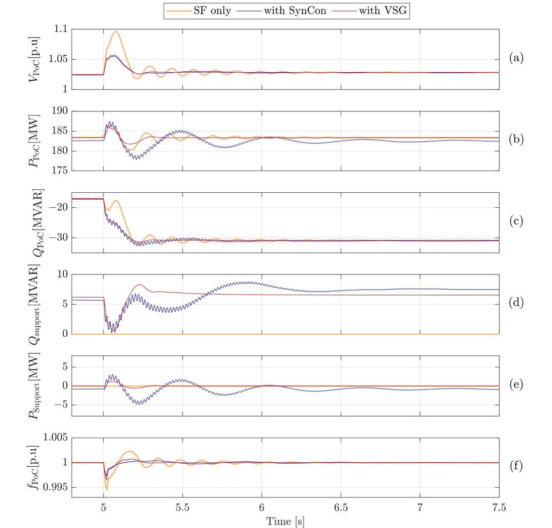
Figure 7 - The responses of the system to a step change from 1.0 pu to 1.05 pu in the PoC voltage: (a) the PoC voltage, (b) the active power transfer measured at the PoC, (c) the reactive power transfer measured at the PoC, (d) the reactive power contributed by the remediation asset, and (e) the active power contributed by the remediation, (f) the frequency at the PoC
4.3. Active Power Reference change
The previous two tests show improvements brought by the VSG in voltage contingencies. In this section, the performance of the SynCon and the VSG is examined in an active power step change event. For example, at 5 s, a step change from 0.85 pu to 0.65 pu is applied on the active power reference. The responses of the three cases are shown in Figure 7.
In general, the SF itself can smoothly transit to the new power setpoint with negligible oscillations and overshoots. However, with the SynCon being active, severe undamped oscillations occur in all the responses after the step change, reflecting the system's unstable operation. The unstable behaviour of the SynCon is because of its exciter interaction and the SF [12]. The peak-peak magnitude of the active power oscillation is almost 80 MW. Additionally, the voltage persistently fluctuates between 1.06 pu and 0.96 pu. These responses will result in a disconnection of the system from the grid in reality. These oscillatory behaviours are not observed in the case with VSG activated. The VSG retains the smooth transition of the SF and further restrain the voltage overshoot right after the step change thanks to its fast reactive power control. This test reveals the risk of instability caused by the interaction between the SynCon and the SF in a power setpoint variation event, while this issue is not present if the VSG is used.
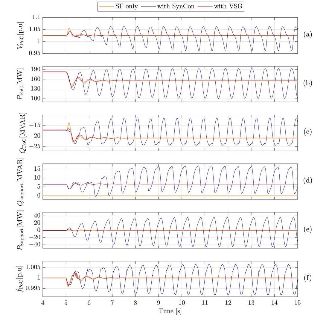
Figure 8 - The responses of the system to a step change from 0.85 pu to 0.65 pu in the active power reference: (a) the PoC voltage, (b) the active power transfer measured at the PoC, (c) the reactive power transfer measured at the PoC, (d) the reactive power contributed by the remediation asset, and (e) the active power contributed by the remediation , (f) the frequency at the PoC
4.4. Frequency Disturbance
In this test, a frequency disturbance is synthesized by ramping the grid's frequency from 50 Hz to 51 Hz at a rate of 2 Hz/s. This disturbance occurs at 5 s in Figure 8. As a result, the active power responses in all three cases decrease to tackle the frequency rise.
Without the SynCon and the VSG, severe oscillation is observed in the voltage response even in the steady-state after the frequency ramp, which causes oscillations in the SF's active and reactive power responses. The presence of the SynCon helps dampen the voltage but, similarly to previous tests, pollutes the active power response with low-frequency oscillations. The magnitude of the power oscillation in the case with SynCon is 15 W peak-peak initially and diminishes to zero after 15 s. In the case with the VSG, both the voltage and the power responses experience smooth transients and stably settle after the disturbance. Thus, these responses are oscillation-free in both the transient and steady-state of the system. Moreover, thanks to its battery storage system, the VSG can absorb active power from the grid to support the grid frequency in this test, which is not achievable with SynCon.
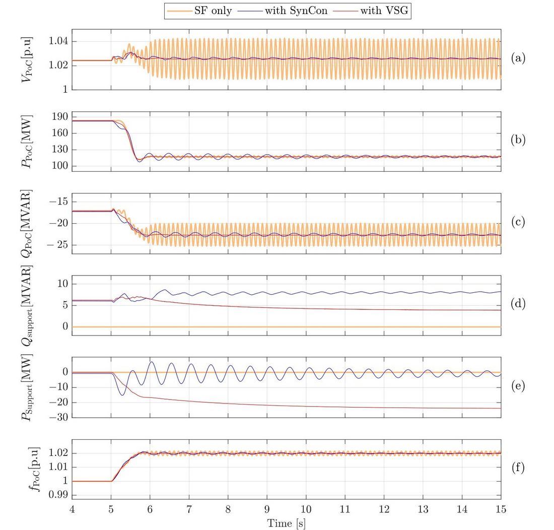
Figure 9 - The responses of the system to a frequency ramp from 50 Hz to 51 Hz at a rate of 2Hz/s: (a) the PoC voltage, (b) the active power transfer measured at the PoC, (c) the reactive power transfer measured at the PoC, (d) the reactive power contributed by the remediation asset, and (e) the active power contributed by the remediation, (f) the frequency at the PoC
5. Conclusions
Due to a need for performance comparison between SynCons and VSGs in weak grid integration of renewable energies, in this paper, the solar farm in the SMIB scenario with low SCR at the PoC is modelled in PSCAD/EMTDC. Different Australian grid code tests, such as frequency disturbance, voltage disturbance, reference active power step, and fault ride-through capability, are applied in the system considering three configurations: with SynCon, with VSG, and without any asset. The simulation results show the significant impact of VSG on solving stability issues in weak grids compared to the system without any assets. Also, the results illustrate that VSGs can dampen oscillations in the system after disturbances and perform better than SynCons in the frequency disturbances and active power setpoint change. Clearly, the VSG performs better in all tests scenarios conducted in this study.
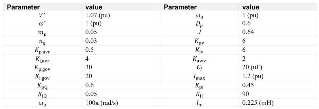
Appendix - Control parameters of the VSG
Aknowledgment
We acknowledge FIMER contribution by providing a PSCAD solar inverter model for the purpose of this study.
References
- P. Tielens, and D. Van Hertem, "The relevance of inertia in power systems," Renewable and Sustainable Energy Reviews, vol. 55, pp. 999-1009, 2016.
- D. Kim, H. Cho, B. Park, and B. Lee, "Evaluating Influence of Inverter-based Resources on System Strength Considering Inverter Interaction Level," Sustainability, vol. 12, no. 8, pp. 3469, 2020.
- AEMO, "System Strength Impact Assessment Guideline," 2018.
- S. Hadavi, M. Z. Mansour, and B. Bahrani, "Optimal Allocation and Sizing of Synchronous Condensers in Weak Grids With Increased Penetration of Wind and Solar Farms," IEEE Journal on Emerging and Selected Topics in Circuits and Systems, vol. 11, no. 1, pp. 199-209, 2021.
- M. Z. Mansour, S. P. Me, S. Hadavi, B. Badrazadeh, A. Karimi, and B. Bahrani, "Nonlinear Transient Stability Analysis of Phased-Locked Loop Based Grid-Following Voltage Source Converters Using Lyapunov's Direct Method," IEEE Journal of Emerging and Selected Topics in Power Electronics, pp. 1-1, 2021.
- Y. Cheng, S. Huang, J. Rose, V. A. Pappu, and J. Conto, "ERCOT subsynchronous resonance topology and frequency scan tool development.", 2016 IEEE Power and Energy Society General Meeting (PESGM), pp. 1-5.
- W. Du, Q. Fu, H. Wang, and Y. Wang, "Concept of modal repulsion for examining the subsynchronous oscillations caused by wind farms in power systems," IEEE Transactions on Power Systems, vol. 34, no. 1, pp. 518-526, 2018.
- R. Yan, T. K. Saha, F. Bai, and H. Gu, "The anatomy of the 2016 South Australia blackout: A catastrophic event in a high renewable network," IEEE Transactions on Power Systems, vol. 33, no. 5, pp. 5374-5388, 2018.
- H. T. Mokui, M. A. Masoum, and M. Mohseni, "Review on Australian grid codes for wind power integration in comparison with international standards." pp. 1-6.
- AEMC, "National Electricity Rules Version 160," AEMC, 2021.
- T. de Atholia, G. Flannigan, and S. Lai, "Renewable energy investment in Australia," Bulletin—March Quarter, 2020.
- S. Hadavi, D. Rathnayake, S. G. Jayasinghe, A. Mehrizi-Sani, and B. Bahrani, "A Robust Exciter Controller Design for Synchronous Condensers in Weak Grids," IEEE Transactions on Power Systems, pp. 1-1, 2021.
- D. Tzelepis, E. Tsotsopoulou, V. Nikolaidis, A. Dysko, V. Papaspiliotopoulos, Q. Hong, and C. Booth, "Impact of synchronous condensers on transmission line protection in scenarios with high penetration of renewable energy sources," 2020.
- J. Jia, G. Yang, A. H. Nielsen, E. Muljadi, P. Weinreich-Jensen, and V. Gevorgian, "Synchronous Condenser Allocation for Improving System Short Circuit Ratio." 2018 5th International Conference on Electric Power and Energy Conversion Systems (EPECS). IEEE pp. 1-5.
- D. B. Rathnayake, M. Akrami, C. Phurailatpam, S. P. Me, S. Hadavi, G. Jayasinghe, S. Zabihi, and B. Bahrani, "Grid Forming Inverter Modeling, Control, and Applications," IEEE Access, vol. 9, pp. 114781-114807, 2021.
- J. Driesen, and K. Visscher, "Virtual synchronous generators." 2008 IEEE power and energy society general meeting-conversion and delivery of electrical energy in the 21st century. pp. 1-3.
- D. Pan, X. Wang, F. Liu, and R. Shi, "Transient stability of voltage-source converters with grid-forming control: A design-oriented study," IEEE Journal of Emerging and Selected Topics in Power Electronics, vol. 8, no. 2, pp. 1019-1033, 2019.
- Y. Yang, Q. Ye, L. J. Tung, M. Greenleaf, and H. Li, "Integrated Size and Energy Management Design of Battery Storage to Enhance Grid Integration of Large-Scale PV Power Plants," IEEE Transactions on Industrial Electronics, vol. 65, no. 1, pp. 394-402, 2018.
- X. Meng, J. Liu, and Z. Liu, "A generalized droop control for grid-supporting inverter based on comparison between traditional droop control and virtual synchronous generator control," IEEE Transactions on Power Electronics, vol. 34, no. 6, pp. 5416-5438, 2018.
- Z. Shuai, C. Shen, X. Liu, Z. Li, and Z. J. Shen, "Transient Angle Stability of Virtual Synchronous Generators Using Lyapunov's Direct Method," IEEE Transactions on Smart Grid, vol. 10, no. 4, pp. 4648-4661, 2019.
- T. Qoria, F. Gruson, F. Colas, X. Kestelyn, and X. Guillaud, "Current limiting algorithms and transient stability analysis of grid-forming VSCs," Electric Power Systems Research, vol. 189, pp. 106726, 2020.
- Y. Li, and B. Jones, "The Use of Extreme Value Theory for Forecasting Long-Term Substation Maximum Electricity Demand," IEEE Transactions on Power Systems, vol. 35, no. 1, pp. 128-139, 2020.
- J. Z. Zhou, H. Ding, S. Fan, Y. Zhang, and A. M. Gole, "Impact of Short-Circuit Ratio and Phase-Locked-Loop Parameters on the Small-Signal Behavior of a VSC-HVDC Converter," IEEE Transactions on Power Delivery, vol. 29, no. 5, pp. 2287-2296, 2014.
- C. Yang, L. Huang, H. Xin, and P. Ju, "Placing Grid-Forming Converters to Enhance Small Signal Stability of PLL-Integrated Power Systems," IEEE Transactions on Power Systems, 2020.
- R. Rosso, S. Engelken, and M. Liserre, "Robust stability investigation of the interactions among grid-forming and grid-following converters," IEEE Journal of Emerging and Selected Topics in Power Electronics, vol. 8, no. 2, pp. 991-1003, 2019.
- M. G. Taul, X. Wang, P. Davari, and F. Blaabjerg, "Current limiting control with enhanced dynamics of grid-forming converters during fault conditions," IEEE Journal of Emerging and Selected Topics in Power Electronics, vol. 8, no. 2, pp. 1062-1073, 2019.
- S.-H. Huang, J. Schmall, J. Conto, J. Adams, Y. Zhang, and C. Carter, "Voltage control challenges on weak grids with high penetration of wind generation: ERCOT experience." pp. 1-7.