Digitalization solutions for substation planning, design, construction, operation and maintenance
Authors
M. NAKAHATA - TEPCO Power Grid, Inc., Japan
S. NOGUCHI - Chubu Electric Power Co., Inc., Japan
S. IWASAKI - Kansai Transmission and Distribution, Inc., Japan
H. SUGIYAMA - Toshiba Energy Systems & Solutions Corp., Japan
M. FURUYA - Hitachi, Ltd., Japan
K. ITO - Mitsubishi Electric Corp., Japan

Summary
The environment in which electric power companies operate in Japan has changed significantly. Electric power companies are required to maintain their equipment within a limited budget even as the number of personnel decreases and with aging equipment, such as transformers. On the other hand, Information and Communication Technology (ICT) and Internet of Things (IoT) technologies, such as Artificial Intelligence (AI), sensor, drones, Mixed Reality (MR) and Building Information Modelling (BIM), are becoming increasingly advanced, and in recent years, the digitization of business is also progressing rapidly. Therefore, the usability of substations are expected to improve by combining digital technology with maintenance data and the know-how cultivated to date. It is also necessary to increase the value of substation works and various data while solving problems such as the decreasing number of personnel and aging equipment. The concept of digitalizing the overall substation works such as planning, design, construction, operation and maintenance (O&M) is called “the digital substation concept”. The realization of the digital substation will transform substation works and create new value, improving the value of companies. In this way, digital transformation (DX) in the electric power company will be realized by utilizing digital technology and transforming substation works. For DX, realization of the digital substation will be essential.
Currently, we are verifying various digital technologies for the realization of digital substations, some of them are applied to actual operation. This paper introduces the digital substation concepts and results of related studies.
Keywords
ICT - IoT - AI - Sensor - Drone - MR - BIM - Digital Substation - Digital Transformation - Digital Technology1. Introduction
In Japanese power transmission and distribution business, renewable energy power sources will increase with the progress of “5Ds”, which collectively refers to “population decline / depopulation”, “decarbonization”, “decentralization”, “digitalization”, and “deregulation”. On the other hand, it is assumed that large-scale power supplies and the supply sources of adjustment and inertia will decrease. Furthermore, it is forecasted that electric power consumption will increase because of consideration for the environment, the improvement of battery technology, and widespread use of electric vehicles and all-electric homes. Therefore, in this way, the environment surrounding the electric power company has begun to undergo major changes, and it is more important than ever to determine the quantity and quality of the supply sources necessary to ensure quality and security of supply. Further reliable investment and cost recovery of the electric power company is required. Therefore, in addition to the digitization of conventional operation, it is very important to collect and analyse the information obtained, and to advance condition based maintenance (CBM) and asset management, and hence digitization is being studied in various countries around the world.
Digitizing all substation works such as substation planning, design, construction, operation and O&M is called “the digital substation concept”. By utilizing digital technology, maintenance data is automatically obtained from these data, equipment specifications and other data related to substation equipment are seamlessly integrated and analysed, substation works such as maintenance and planning of replacement and repair of equipment are automated. Such a new substation work cycle will realize the higher efficiency of substation works and provide labour savings. For example, by using drones, cameras, or sensors instead of a patrol / inspection, the work that was previously performed by a person seconded to the site are no longer required. In addition, it is possible to achieve advance awareness of abnormal signs of operation that cannot be detected by human beings. In construction design, it has been confirmed that the creation and utilization of three dimensional (3D) model of substations and equipment can make design work more efficient [1].
As a substation database, BIM technology can be constructed after combining 3D models with equipment data obtained from cameras and sensors. BIM technology has become a commonly used tool for minimizing project risk and enabling advanced simulation studies [2]. BIM is used in a form specialized for substations. For example, when a substation is constructed, the substation equipment is replaced with a 3D model for simplification, although a building is created in detail by the general BIM used in the building department. It is planed that the maintenance data, 3D model date, equipment specification and so on is stored in BIM. Asset management is expected to advance by integrating these system. In addition, the creation of new value and business for the electric power company is anticipated by sharing substation data with data from other industries.
In this way, the realization of the digital substation by promoting the advancement of substation works and labour saving will contribute to the realization of DX.
2. Digitization solutions
To realize a digital substation, we are currently verifying digitalization solutions for substation planning, construction, design, and O&M. This section introduces the concept and verification results.
2.1. Digital Substation Concept
The main items we want to realize in the digital substation are as follows:
- Labour saving for inspection and patrol of substation
- Advanced CBM using sensing technology
- Labour saving in construction design and on-site construction (metallic wire-less using IEC 61850 communication rules)
- Reduction of local skill-level requirement
- Optimization of renewal interval
A fundamental review is made of the conventional substation work cycle and the new substation work cycle is constructed (Figure 1).
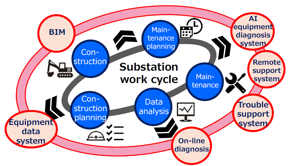
Figure 1 - Substation work cycle
2.2. Patrol and Inspection Work
Work Network cameras (NW cameras) and drones are used for patrol and inspection in the digital substation. In particular, in patrols and inspections, it is important not only to select digital devices, but also to integrate it with the maintenance know-how cultivated so far.
In distribution substations with a small site area, NW cameras are being installed sequentially, and the images taken with NW cameras are diagnosed by AI to detect abnormalities and signs of potential abnormalities, and automatically digitize analog indicating meters. In transmission substations having a large site area, the installation of NW cameras is uneconomic because of the huge amount of equipment required. In other countries, selfpropelled robots are the mainstream of diagnostic tools. Hence, drones are selected primarily in consideration of problems with infrastructure such as steps and gravel roads and economic efficiency. NW cameras are installed only at locations that cannot be confirmed by drone. Since drones are easily affected by the weather and there are battery issues, the use of robotics will be verified in the future. For images taken with a drone, AI is used for diagnosis as with a NW camera.
2.2.1. Drone patrol
The drone verification tests included autonomous flight of programmed routes, flight under strong magnetic fields, and acquisition of video data.
Firstly, the inspection route in the substation was programmed and the autonomous flight was verified while photographing the equipment (Figure 2). As a result of the verification, the drone flew as programmed, and it was confirmed that obstacles could be avoided by detecting obstacles using an infrared sensor. However, in some of the images taken, it was not possible to determine whether there was an abnormality in the equipment due to the effect of backlighting and the equipment itself was not visible in the evening (Figure 3). To realize a drone patrol, it is necessary to consider the patrol route and the patrol time for each substation. In addition, although the flight altitude was 5 m from the home point, the ground height changed due to the altitude in the substation, so the object could not be seen depending on its location. Therefore, there is a need for technology that uses altitude sensors to maintain the altitude from the ground level at a specified value.
Regarding drone flight in the substation, it is generally considered that drones are not suitable for flight in substations because they are easily affected by magnetic fields. However, as a result of flying several metres over a transmission line carrying a load current of about 3000 A at a 500 kV substation, no compass error occurred in the drone used. A compass error occurred several times in a place where steel pipe piles for ground reinforcement were buried in the ground, but the programmed flight was continued. However, after the drone landed, an error occurred and it was necessary to reboot for flying again. This time, the reasons for the error could not be clarified, but in order to reboot the drone, someone need to go to the substation, which is a major issue for unmanned drone patrol and inspection. In the future, it will be necessary to clarify the conditions under which compass errors occur.
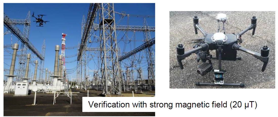
Figure 2 - Drone verification test in the substation
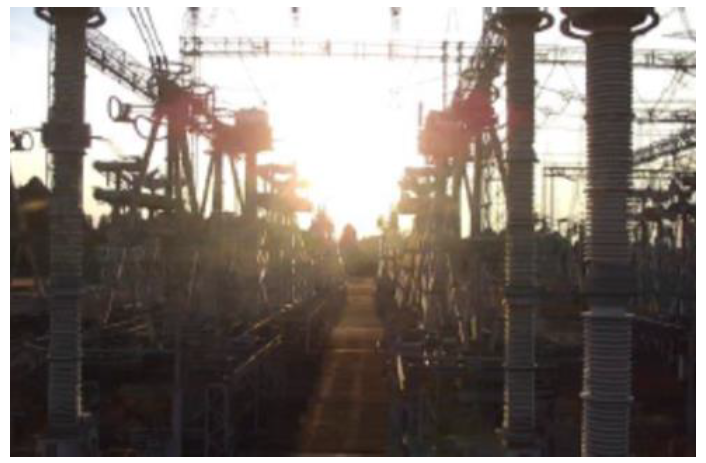
Figure 3 - Drone patrol (Backlight)
2.2.2. AI diagnostic system
Patrol of the equipment is analysed and evaluated based on past failure and accident data, and the content is carefully revised to reflect the location and the actual conditions of the equipment, whilst maintaining the security level of the substation equipment. In order to cope with further personnel reduction and aging equipment in the future, substation diagnosis using AI technology was verified.
With regard to the system configuration, a NW camera is installed in a location where the equipment status can be monitored, and equipment diagnosis is performed using AI on the captured still images and videos. Figure 4 shows an overview of the entire system. AI diagnosis images are shown in Figure 5.
“Missing information rate” and “misinformation rate” are used as indicators to express diagnostic accuracy. Unreported (missing information) means that the abnormality was judged to be normal, and for the target of 20 % or less, the target value was achieved (Table 1). A false alarm (misinformation) is to judge normality as abnormal, and a target of 20 % or less is set. Although false alarms may be over-detected, they do not overlook abnormalities, so accuracy is checked whilst in operation. The system will be tuned after its introduction to further improve accuracy.
The verification results for oil leakage detection and abnormal noise detection are introduced hereafter.
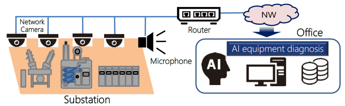
Figure 4 - AI diagnostic system
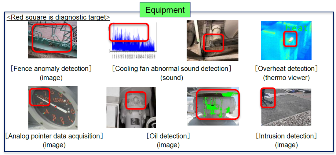
Figure 5 - AI diagnostic image
| Detection item | Missing information rate |
|---|---|
| Transformer oil leakage | 15 % (Flange), 20 % (Floor) |
| Abnormal noise of cooling fan | 0 % |
| Broken fence | 0 % |
| Illegal dumping | 6 % |
| Overheating of substation equipment | 0 % |
| Lighting of control panel lamp | 0 % |
| Sticking of oil level indicator | 0 % |
Detection of oil leakage in transformer flanges, etc., is realized by a combination of differential detection and segmentation detection and business settings. The business setting is used to store the point (a pre-set function) where the oil leakage is to be confirmed in advance. Differential detection is a function that detects an area where a difference has occurred compared to the previous photograph. Segmentation detection is a function that detects oil leaks in pixel units of a captured image. By combining the two detection technologies according to the progress of an oil leakage, the accuracy of oil leakage detection is improved. In establishing the oil leakage detection technology, verification was performed by simulating abnormalities in multiple units (Figure 6). As a result, it was possible to accurately determine the flange part, but it was difficult to distinguish between the oil leakage and a shadow on the floor surface, the missing information rate was 50 %. However, by continuing to tune the AI, this rate has now improved to 20 %. In terms of the environment, although it was possible to make accurate judgments at indoor and underground substations, it became difficult to make judgements for outdoor substations at night and in the rain. For this reason, oil leakage detection at outdoor substations is currently supported by operations performed during clear days. In the future, this problem will be solved by adding the algorithm conditions such as weather conditions.
It has been confirmed that the inspection time can be reduced by more than 50 % by utilizing an AI diagnostic system, the system is gradually being introduced to distribution substations. In addition, in cooperation with not only the NW camera in the substation but also the images taken by the drone, an AI diagnostic system will be developed for transmission substations in the future.
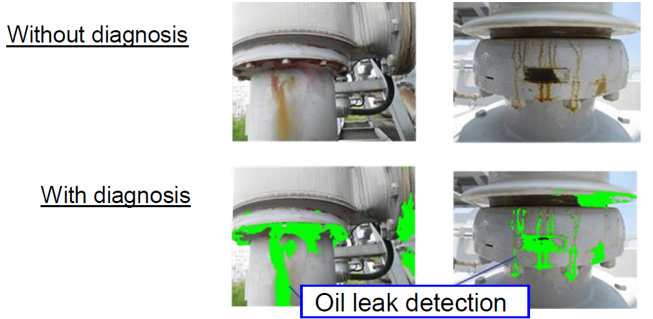
Figure 6 - Oil leak detection
Conventional acoustic analysis is a mechanism that frequency-decomposes sound data and determines normality / abnormality based on rules, so there is an acoustic difference between normal and abnormal sounds after collecting abnormal sounds. At first it is necessary to develop rules after understanding the differences between normal and abnormal sounds. Further, since it is necessary for the user to assume and set the parameters of the expected or anticipated normal sounds, it is difficult to detect abnormalities that are not assumed.
On the other hand, one of the features of the unusual sound detection AI algorithm is that it can be detect abnormal sounds by learning only normal sounds without prior learning of abnormal sounds. By learning only normal device operating sounds, damage and deterioration of bearings can be identified and detected.
Firstly, a normal learning model is created by learning normal sounds, and the degree of deviation from the distribution of normal sounds learned by the subject is calculated as an original acoustic score (Figure 7). When the acoustic score exceeds a pre-set threshold, it is judged as abnormal (Figure 8).
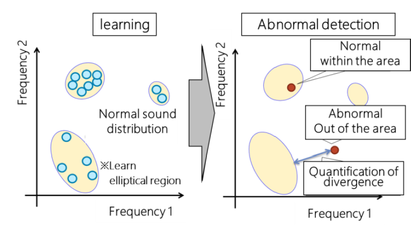
Figure 7 - Sound score calculation image
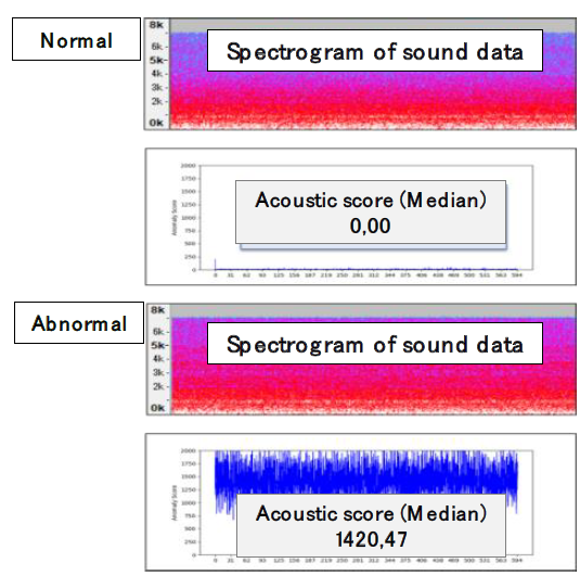
Figure 8 - Abnormal sound detection
2.2.3. Sensing
In order to save labour in maintenance work, it is necessary to shift from regular periodic inspections to inspections according to the state of equipment and detect signs of abnormalities at an early stage. Therefore, various sensors are attached to the equipment, and the status of the equipment is monitored in real time. The equipment monitoring system consists of three elements. One of the elements is a sensor such as an oil temperature sensor. It is also a device monitoring unit that monitors and diagnoses the state of the device by taking in sensor information. The third element is a human interface used to display the information. When selecting a sensor, it is particularly important to ensure that the mounting structure is simple and easy to replace in consideration of mounting and replacement work on existing equipment. The system can detect abnormal signs by performing a trend analysis, comparing not only the evaluation by comparison with the threshold value, but also the results of past operations such as circuit breaker opening.
Data transmission is based on IEC 61850 transmission specifications using an optical LAN, and cable work can be drastically reduced compared to conventional metallic cables.
Data transmission is based on IEC 61850 transmission specifications using an optical LAN, and cable work can be drastically reduced compared to conventional metallic cables. Sensor information is used not only for equipment diagnosis but also for the dynamic rating. The limit value of the transformer winding temperature is calculated based on environmental effects such as ambient temperature, wind direction and wind speed, as well as the effect of current flow. Normally, the ambient temperature uses a fixed value calculation based on past results. If the ambient temperature is low, a margin is created in the winding temperature limit value and the transmittable capacity increases. Therefore, by acquiring the ambient temperature in real time (dynamic) using a sensor, it is possible to dynamically calculate the transmittable capacity. As a result, it is possible to make maximum use of the capacity of the equipment and realize network operation including power generation suppression (Figure 9, 10). The dynamic rating makes it possible to suppress investment for equipment expansion. Actual operating equipment equipped with this monitoring system has already commenced, and will continue to verify the system during in-service operation.
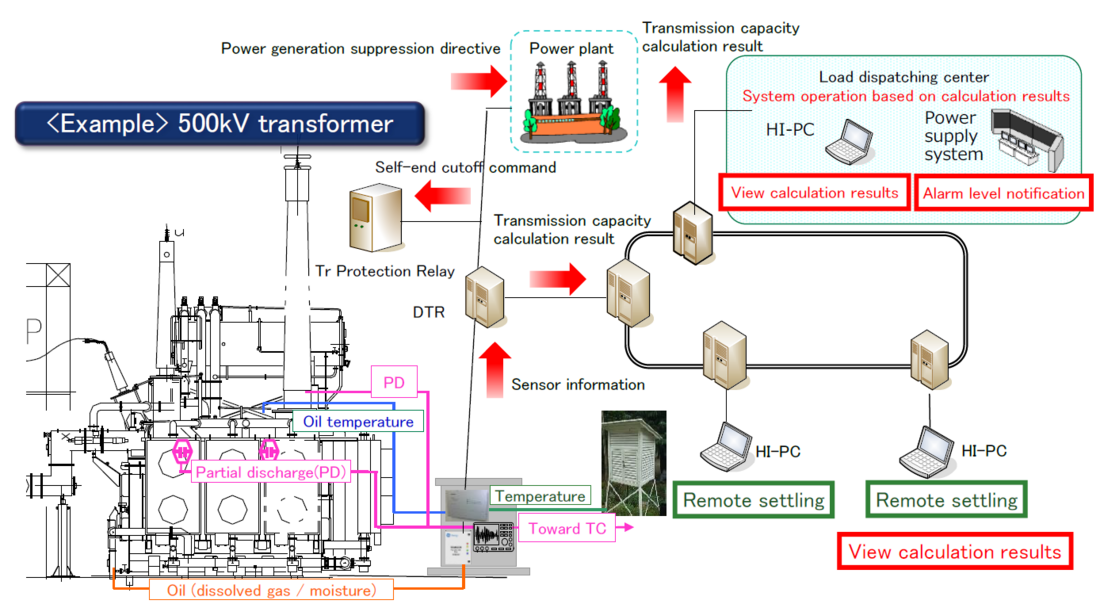
Figure 9 - Dynamic rating system
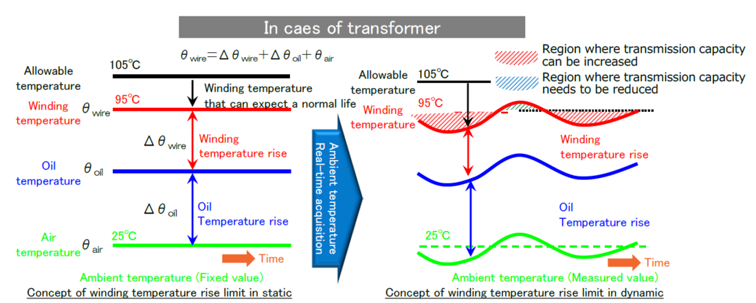
Figure 10 - Image of dynamic rating
2.3. Construction and design work
With regard to 3D technology, the use of 3D models, such as measuring dimensions with data obtained from 3D scanner devices and reducing the amount of on-site research, has dramatically improved construction design and construction work (Figure 11). However, when creating a 3D model of a substation, some problems still remain. For example, the technology for converting 3D scanned data to 3D-CAD clearly is difficult, and at present, human correction is required. Also, in terms of operation, there are many issues to be considered when deploying this technology widely, such as the need to update the 3D model every time equipment is updated. In the future, the operation methodology of 3D models will be considered while continuing to verify the 3D software.
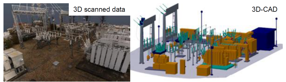
Figure 11 - 3D substation model
2.4. Equipment operation, accident and trouble handling
Operational support tools can be enhanced by using wearable cameras, tablets, VR (Virtual Reality) and MR and trouble support tools can be verified for each equipment operation and trouble correspondence.
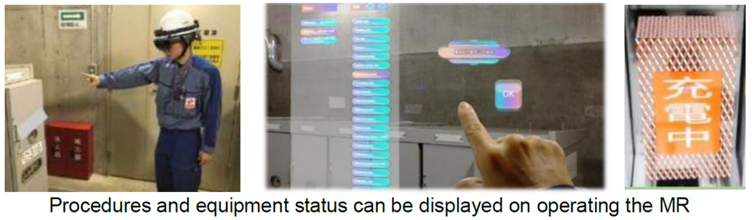
Figure 12 - Operations support verification using MR
Real space is scanned using MR, cyber space is constructed, and linked to system information / operation procedure manual (Figure 12). In particular, smart glass image recognition is used to prevent human error during operation. It is possible to proceed to the next step only when the name plate of the operation location is recognized and collated with the operation location in the operation procedure manual. In the future, the interface will be improved to improve operability. For trouble-shooting, it is possible to improve the sign detection and speed up emergency response by checking the abnormalities by overlaying past knowledge and local sensor information on the actual product. As a result, even inexperienced workers are able to work as experts, and skill-less operations can be achieved. There are also cases where VR is used for safety education. The curriculum provides a virtual experience covering potential disasters such as a crash or an electric shock that are difficult to simulate, and hence aim to improve the safety awareness of workers (Figure 13).
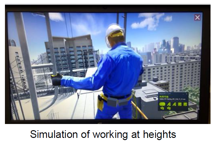
Figure 13 - Safety awareness training using VR
Digital technology is also used for technology succession. In order to visualize the viewpoint confirmed by veteran workers during patrols, eye tracking was performed using eye tracking technology. This is a result of a low gaze recognition rate due to the shift of the helmet caused by movement, etc., and it is necessary to devise a technique to fix the gaze in an application.
2.5. Planning work
A comprehensive evaluation of equipment data obtained from sensors, life cycle costs, equipment importance and other information is performed, and equipment renewal plans are automated. This will work in cohesion with the asset management system by automatically scoring equipment risks and the impacts of failures (Figure 14).
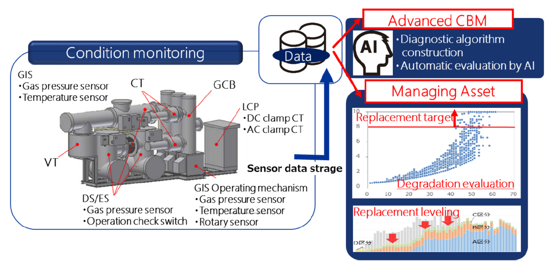
Figure 14 - Asset Management
2.6. 3D platform construction
The conventional equipment management system (equipment specifications, inspection history, abnormal state management data, etc.) will work with drawing data and sensor data to the substation 3D model. By doing so, a substation equivalent to an actual substation is realized in the digital space, it is a “digital twin”, and BIM as a 3D data platform is built. Generally, a BIM builds to the inside, while the substation equipment is replaced with a 3D model which is obtained from a 3D scanner for simplification. Integration with the various digital techniques (AI equipment diagnosis, drone, VR / MR) and asset management system will be integrated into a platform for substation works.
By realizing BIM, the same information as the actual equipment is realized in 3D in digital space, so it can be visualized as in reality. In particular, there is no need to visit the substation by designing a 3D model during the construction design phase, and increases in the efficiency of design work is expected.
However, as described in Section 2.3, there remain issues in regard to 3D modelling. In particular, in order to maintain BIM as a valuable system, it is necessary to incorporate the updating of 3D data (reflecting the physical space into cyber space) into the routine work after equipment update. Therefore, it is essential to formulate and ensure the implementation of 3D data operation rules.
3. Future prospects
In this paper, verification results of our digital technology were introduced. Verification of work at the field level, such as substation design, construction, and O&M, has progressed, and AI diagnostic system and sensing is sequentially introduced and operated in a substation. On the other hand, digitalization of planning work will still take time because it is necessary for further verification, especially BIM.
The direction of the digital substation is not only to digitize the substation, but also to include the grid. In addition to digitally linking equipment, it is possible to coordinate and manage the entire substation work such as equipment planning, construction design, and O&M. In order to realize the digital substation, continuous digital technology verification is needed.
As substation works become more digital in the future, it is assumed that data from sensors will be accumulated in large quantities. It is expected to create new value by storing and sharing the data of the electric power companies and other companies such as weather companies. On the other hand, new problems such as the durability and renewal cycle for digital devices such as sensors, NW cameras, drones, and so on, must be solved.
In order to realize the digital transformation in electric power companies, it is important not only to realize the transformation of substation works using digital technology, but also to increase the utility value of data that will be acquired and to open up new markets.
- [1] S. Ichihara, T. Kobayashi, M. Yoshida “Improvement in Substation Design and Construction through Application of 3D Modelling” (CIGRE 2018 Session paper B3-214, August 2018)
- [2] [a] J. Correa, J. Gercia “Software for optimization and time reduction in substation design, using BIM Technologies, advanced information systems and knowledge management” (CIGRE 2014 Session paper B3-101, August 2014) [b] M. Kokorus, W. Eyrich & R. Gacanovic “Implementation of Building Information Modelling (BIM) process in substation design software to increase design quality” (CIGRE 2016 Session paper B3-209, August 2016)