Model Verification for Inverter-Based Resources for Improved Bulk Power System Reliability
Authors
R. QUINT, R. BAUER - North American Electric Reliability Corporation, USA
D. RAMASUBRAMANIAN - Electric Power Research Institute, USA
A. ISAACS - Electranix Corporation, Canada
S. PANT - General Electric, USA
S. ZHU - California Independent System Operator, USA
D. PIPER - Southern California Edison, USA

Summary
The North American bulk power system (BPS) is facing a rapid growth in inverter-based resources (IBRs), dominated by the growth of solar photovoltaic (PV) and wind resources. Recent grid disturbances in California that unexpectedly experienced a significant drop in power output from solar PV have sparked industry-wide efforts to ensure BPS reliability and accurate planning and operating studies. Specifically, it was determined that the mathematical models used to represent these resources do not accurately capture the large disturbance behaviour of the equipment installed in the field. The Blue Cut Fire and Canyon 2 Fire disturbances led the North American Electric Reliability Corporation (NERC) and its industry stakeholders to key findings and recommendations focused on IBR performance and modelling. This paper describes the latest industry efforts to address modelling and model verification gaps identified by NERC and suggests new recommended practices for the future. In North America, gaps in modelling (both parameterization and model structure) and model verification appear to be systemic in nature and require industry cooperation to address. These issues become increasingly pertinent to address as instantaneous penetrations of IBRs approach 100% penetration. Industry efforts should be focused on accurate model parameterization, verification of rms positive sequence stability models, detailed electromagnetic transient (EMT) simulations, and changes to transmission planning study approaches.
Keywords
electromagnetic transient simulation - inverter-based resource - modelling - momentary cessation - reliability1. Introduction
Rapid growth of BPS-connected IBRs across North America is challenging transmission planning and operating engineers, generator owners and operators, and inverter manufacturers with ensuring that the mathematical models used to represent these resources in steady-state powerflow, dynamics, and short-circuit studies sufficiently represent the actual behaviour of these resources. Disturbance analyses [1],[2] and subsequent NERC Alerts [3],[4] have identified key modelling issues, particularly for solar PV resources connected to the BPS, that need to be addressed by the industry. As the NERC Inverter-Based Resource Performance Task Force (IRPTF) has continued to explore the impacts that IBRs may have on BPS reliability, the following modelling issues have arisen as needing immediate industry attention:
- The majority of rms positive sequence dynamic models that are used to represent solar PV resources in the interconnection-wide planning models are not accurately parameterized to reflect the large disturbance behaviour of these resources, particularly for resources utilizing momentary cessation [1].
- Commonly used dynamic model verification activities, including staged testing, do not invoke a large disturbance behaviour and therefore do not provide the necessary assurance that the provided dynamic models are a suitable representation.
- The existing rms positive sequence dynamic models have limitations, such as in areas of low short circuit strength, that may limit the extent to which they can be used for planning assessments in areas with high penetration of IBRs.
- Areas with high penetration of IBRs may require EMT simulations that represent detailed inverter controls and can capture interactions between these controls and the BPS.
- Many rms positive sequence dynamic models may not be suitably verified using existing small-disturbance verification tests. However, these models can be benchmarked against high-quality or verified EMT models. This should be performed by the entity submitting the models rather than the entity using the models.
- Development and maintenance of EMT models requires care, particularly as their use increases for dynamic performance evaluation and validation of higher order models.
- Systematic tracking documentation of model versions, settings and parameters should be improved throughout the model submission, study phase, commissioning, and post-commissioning phases.
These issues become more complex as the penetration of IBRs continues to grow. This paper elaborates on these issues and presents recommended modelling improvements moving forward.
2. Recent disturbances and NERC alerts key findings
Four notable disturbances in California have resulted in behaviour from BPS-connected solar PV resources that was not widely understood, predictable, or observed in the mathematical simulation models [1,2,5]. The 2018 NERC Alert following the Canyon 2 Fire disturbance identified the following notable key findings related to model quality and the use of these models in reliability studies:
- The majority of BPS-connected solar PV resources employ momentary cessation with a low voltage threshold around 0.86–0.9 pu. About half of the resources can recover current injection to pre-disturbance levels in less than 1 second while the other half have recovery times longer than 1 second.
- The majority of grid planners stated that the dynamic models received from generator owners had errors or deficiencies that made them unusable. These issues included use of obsolete models,[2] incorrect model parametrization,[3] and models that did not properly initialize or obtain a flat no-disturbance simulation.
- Most owners of BPS-connected solar PV resources stated that they could eliminate momentary cessation or that the momentary cessation settings could be changed to improve performance. However, in the months following the NERC Alert, little to no dynamic models were provided by these plant owners for those proposed changes. Therefore, it is unclear whether those changes were made and whether the dynamic models have been updated to adequately reflect either the existing or proposed settings.
The issues described above warrant immediate action by industry to address modelling gaps that may lead to inaccurate simulation results by grid planners. Grid planners were not widely aware of these systemic modelling issues until the NERC Alert analysis and follow-up activities. While momentary cessation has been considered allowable on the distribution system,[4] its use was not expected for BPS-connected IBRs. Inverters in the field at these BPS facilities were set with this operating mode; however, the mathematical models provided to grid planner during the interconnection study process have not been reflective of this behaviour. Incorrect parameterization of the IBR dynamic models has become a systemic modelling issue across North America, and likely is a challenge in many parts of the world.
As a result, industry is seeking improvements to the dynamic models used for BPS reliability studies. For example, the California Independent System Operator (CAISO) and its member utilities have initiated a phased model improvement process. Fig. 1 illustrates the status of the CAISO process as of September 2019. Of 109 dynamic models received in the first phase of review, only 6 models were deemed acceptable. The CAISO identified that the remaining 95 models had issues that need correction before they are considered acceptable. CAISO is using a multi-year process to address these issues with its stakeholders. Until this process is complete, generators that are modelled with unacceptable model parameters may not correctly exhibit a unit’s complete large disturbance behaviour and may cause inaccuracies in study results.
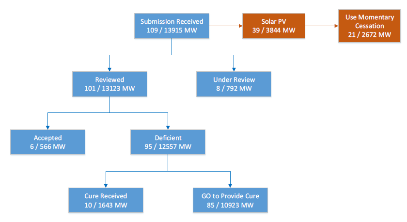
Figure 1 - Example of model improvements at CAISO
3. Reliability studies to ascertain system impact
Data collected following the 2017 NERC Alert after the Blue Cut Fire identified that the majority of BPS-connected solar PV inverters use momentary cessation with the settings shown in Table 1.
| Momentary Cessation Characteristic | Value |
| Low Voltage Threshold [pu] | 0,9 |
| Delay Upon Recovery [sec] | 0,5 |
| Recovery Ramp Rate [pu/sec] | 100%/sec |
Initial simulations explored the extent to which on-fault low voltage conditions could cause widespread momentary cessation from BPS-connected solar PV resources. These simulations modelled a normally-cleared (4 cycle), three-phase bolted fault on EHV buses. Faults were identified to cause BPS voltage to fall below 0.9 pu over a large geographic footprint, as shown in Fig. 2. Analysis of on-fault voltage conditions showed that decreasing the low voltage momentary cessation threshold exponentially decreases the region where momentary cessation could occur. Further, eliminating the use of momentary cessation for BPS-connected solar PV inverters and providing current injection during ride-through operation significantly minimizes the risk of BPS instability issues [6].
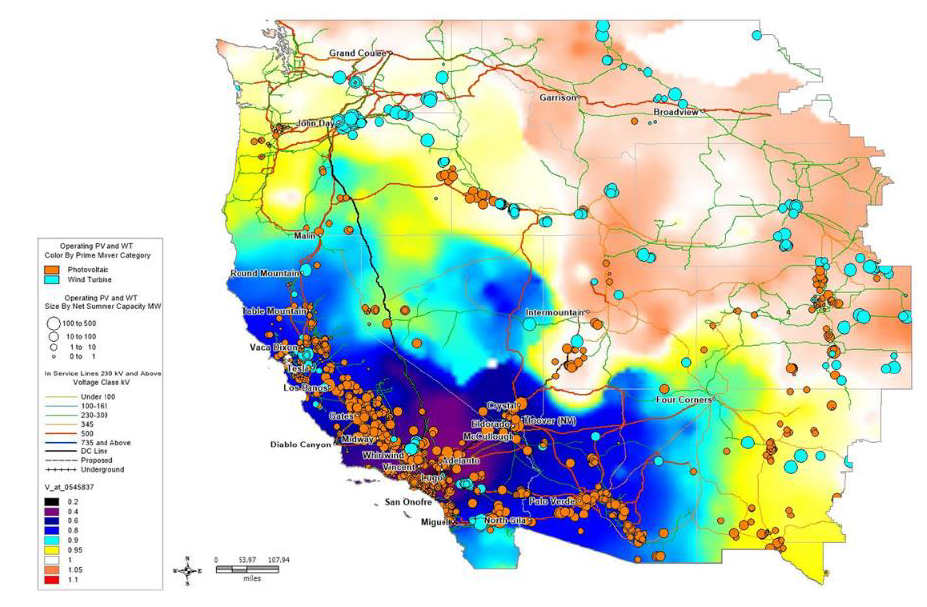
Figure 2 - BPS bus voltages during on-fault conditions for fault in Southern California
To model momentary cessation in a wide-area simulation for the purpose of these tests, a user-written model was created to interact with existing models in the simulation and force them to exhibit momentary cessation with the parameters in Table 1 [5].After screening the Western Interconnection for potential instabilities with the updated user-defined model applied to all BPS-connected solar PV resources, one critical contingency in the Northern California region was identified to potentially cause BPS instability with the wide-area momentary cessation assumptions. This risk was attributed to lack of dynamic reactive support immediately following the fault. About 7,000 MW of BPS-connected solar PV entered momentary cessation (see Fig. 3), assuming the same voltage threshold and delay values for all concerned solar PV resources. Upon fault clearing, solar PV inverters in the Northern California region remained in momentary cessation since voltage did not recover above the low voltage threshold. Lack of dynamic reactive power following fault clearing caused transient voltage to collapse along a major transmission corridor within a couple of seconds (illustrated in Fig. 3).
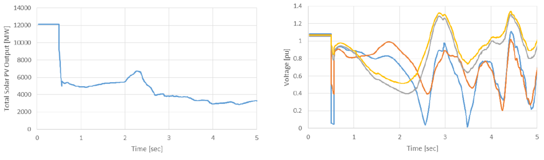
Figure 3 - Total solar PV output and BPS bus voltages in California for N-1 fault event
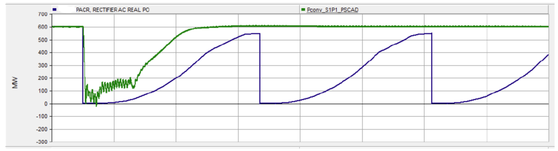
Widespread momentary cessation also interacted with line commutated converter HVDC circuit controls in Southern California. Voltage fell below 0.9 pu (the HVDC inverter-end blocking voltage threshold) and remained depressed below this level due to the momentary cessation actions. This triggered thyristor blocking and power flow immediately reducing to zero on the HVDC circuit. HVDC blocking transferred a significant amount of power to the ac system and was picked up across key interties; however, due to RAS action, BPS stability was maintained. Fig. 4 shows the HVDC and ac intertie flows with HVDC and RAS actions modelled, as well as intertie bus voltage and system frequency.
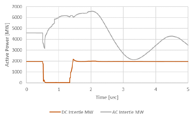
(a) AC and DC intertie flows w/ RAS
Fig. 4. Impacts of momentary cessation
(b) AC intertie voltage w/ and w/o RAS
Fig. 4. Impacts of momentary cessation
(c) System frequency w/ RAS
Fig. 4. Impacts of momentary cessation
These results indicate BPS instability when undesirable momentary cessation settings are used across all BPS-connected solar PV resources. They are not intended to depict actual BPS instability conditions; rather, they illustrate future BPS performance issues if widespread momentary cessation were to continue into the future, and they justify the recommendation to eliminate its use.
4. Improvement in positive sequence models and beyond
Ongoing efforts of NERC IRPTF not only highlighted shortcomings in parameterization of rms positive sequence models but also identified possible shortcomings in the models themselves. Based on the causes of solar PV tripping identified in the disturbance analyses, a few suggested updates to parameterization of the generic positive sequence models are:
- Momentary cessation, if employed, should be modelled using the voltage dependent current limit tables in the generic electrical controller model (i.e., REEC_A/D) [7].
- Ramp rate limits applied by a plant controller, if slower than the ramp rate applied by individual inverter controls, may impact the recovery of active current following fault events and should be modelled appropriately in the generator/converter model (REGC_A).
- If a voltage ride-through model (e.g., lhvrt, or similar) is used to represent low voltage or zero voltage ride-through, then the model should be parameterized according to actual trip settings within the plant (i.e., within the inverter) and not simply parameterized to reflect NERC PRC-024 curves [8]. Studies should be conducted by the plant developer or generator owner to ensure that the values of the model at the inverter allow the plant to meet the NERC PRC-024 voltage ride-through requirements at the point of interconnection, taking into account transformer and collector system impedances. If required, an additional lhvrt model can be applied at the generator bus in the equivalent representation.
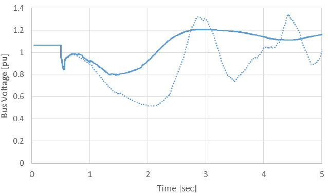
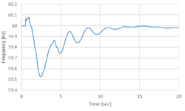
These modelling recommendations are only applicable to behaviour of IBRs that are observable in rms positive sequence simulations. With increasing amounts of BPS-connected IBRs connected to regions of the network with lower short circuit strength, fast inverter control loops (whose dynamics are presently not explicitly represented in state-of-the-art rms positive sequence dynamic models) could enter an oscillatory mode upon occurrence of a large disturbance event. Fig. 5a shows an example of a fault simulation where the rms positive sequence dynamic models incorrectly predicted a stable response while detailed EMT models show instability. Alternatively, there can be situations where the rms positive sequence dynamic model could predict instability while the EMT model of the same plant under the same disturbance may demonstrate a stable response (shown in Fig. 5b). In such a scenario, parameterization of the rms positive sequence model should be verified.
(a) Response of VSC-HVDC. Transient stability simulation predicts stability; detailed EMT simulation predicts instability. (Blue = EMT, Green = rms)
Figure 5 - Model verification between EMT and rms positive sequence dynamic models
(b) Response of VSC-HVDC. Transient stability simulation predicts instability; detailed EMT simulation predicts stability. (Green = EMT, Blue = rms)
Figure 5 - Model verification between EMT and rms positive sequence dynamic models
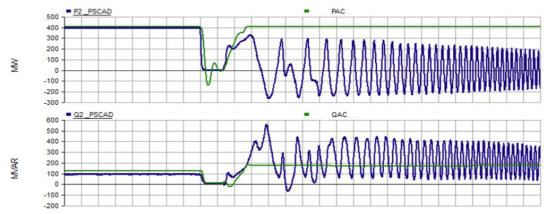
New rms positive sequence converter models are presently being developed to allow grid planners to investigate, at a high-level, during an initial generator interconnection study, the potential for controller oscillatory behaviour of the inner current control loop in combination with the phase lock loop (PLL) for a low short circuit strength condition [9]. Fig. 6 shows an example simulation comparing the new model under development (green), an EMT representation (blue), and existing state-of-the-art rms positive sequence dynamic model (orange).
While the new positive sequence model is able to represent oscillatory behaviour, it is not an exact match with the EMT results. However, an exact match between these models is not expected as there are many assumptions made while building generic rms positive sequence dynamic models and also while carrying out positive sequence simulations. Thus, the new models are not intended to replace a possible need for detailed three-phase point-on-wave simulations in EMT-type tools. EMT simulations may still need to be performed using vendor-specific detailed models when considering actual equipment design and site tuning for facilities in low short circuit strength regions. However, the new rms positive sequence dynamic model are intended to help bridge the gap between these simulation platforms for longer-term planning studies in order to initiate mitigation mechanisms. Improved models could, to some extent, also help in representing the behaviour of the PLL, protection issues regarding phase jump, and PLL loss of synchronism.
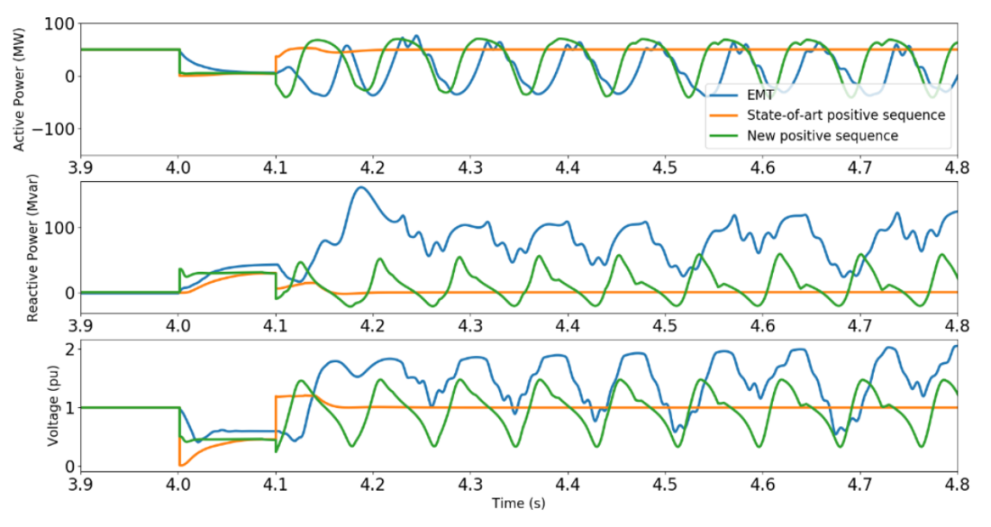
Figure 6 - Performance of improved rms positive sequence model compared with existing state-of-the-art positive sequence models for close-in fault near IBR
5. Recommandations on improvement of model verification
The previous sections illustrated systemic modelling issues regarding BPS-connected IBRs in planning base cases. Many of these issues stem from insufficient verification of the submitted models. The primary contributors to these issues include a lack of understanding of how IBR models are created and verified, how the models should perform, and techniques for verifying these models against actual equipment performance.
Challenges with the Present Plant Model Development Process – RMS Positive Sequence Models
This section describes the typical development of a rms positive sequence solar PV plant model [6]. The model is created by the plant developer for submitting for the interconnection study process. The developer creates the electrical design and chooses components like the inverters and plant controllers, and then gets dynamic models from the inverter and plant controller manufacturers. The developer may then either create the overall plant model in-house, or more likely hire a consultant to develop the plant model. The plant model includes the inverter and plant controls, main power transformers, equivalenced ac collector system and any reactive devices within the plant. Unlike a synchronous machine plant, a transmission connected IBR plant can consist of hundreds of individual inverters each connected through many miles of collector network. Representing the facility to this level of detail is generally not computationally effective in planning studies, and therefore aggregation techniques [10] are frequently used while constructing simulation models.
The developer may also not be very familiar with the grid code requirements with the interconnecting utility or transmission organization and may depend on the consultant to guide them. Typically, during this period, the inverter manufacturer and the plant controller manufacturer are consulted only if there are any problems noticed, either in getting the plant model to run or in the model’s behaviour. The developer’s primary aim during this period is to get the model approved so that an interconnection agreement is obtained.
Parameter or settings changes made by the developer or consultant during the interconnection studies may or may not be communicated back to the inverter or plant controller manufacturer. Even if changes are communicated to the manufacturers, they may not be directed to design and commissioning engineers. Further, control loop modifications or tuning in the inverter and plant controller may be made during the commissioning process. As part of the plant handover process, the developer provides the models to the generator owner. The models originally submitted for the interconnection studies are often the only models available. Since changes may have been made to the control settings, these models may not reflect the actual performance of the installed equipment. Further, changes to control systems may be made during commercial operation and model updates are often not performed to reflect such changes. All these issues highlight major challenges for dynamic model quality for BPS-connected IBRs and strengthen the need for clear requirements for model verification.
Present Inverter-Level Model Verification Processes
There are currently no standardized global requirements for inverter-level model verification. Some manufacturers verify an EMT model against the actual performance of a physical inverter during type-testing or other tests. Different voltage ride-through profiles are tested on the prototype and the EMT model performance is compared against the performance of the inverter. Once the EMT model verification is complete, this model is considered to be the verified “baseline” model, and other EMT and rms positive sequence models are compared against the baseline model. This provides traceability from the physical inverter to the models and increases the confidence of the overall plant model. Manufacturers may also use a hardware-in-the-loop (HIL) platform and verify dynamic models against this baseline model. Some manufacturers develop EMT “real code” models using the actual control code in the inverters and then use these models as the baseline models. Models developed using these techniques are the most accurate types of models and are superior to models assembled using generic control blocks available in commercial software tools. A complete EMT model of the inverter also includes a model of the hardware; if real code models are used as the baseline models, without traceability to the physical inverter, great care must be taken to ensure that the interface between controls and hardware portions of the model works correctly.
Present Plant-Level Model Validation Processes
Plant-level dynamic model verification comparing the modelled response to actual response of the plant to small disturbance tests is generally adequate for the plant level controller, supplemented by appropriate documentation and specification sheets. These types of requirements exist, for example, in the NERC MOD-026-1 and MOD-027-1 [11],[12]. Some transmission entities may require small disturbance testing during plant commissioning. This type of testing verifies model performance for small disturbance behaviour only but does not verify the large signal behaviour typical for BPS fault events or ride-through operation. These types of tests should not be relied upon solely for dynamic model verification.
Recommendations for Future Inverter Model Validation
Since EMT models are currently used for verification of higher-order models and in determining actual system performance in some cases, verification and quality control of the supplied EMT models is becoming increasingly important. The specific process used for verifying any model provided to the transmission planner should be made available to ensure model quality. Real code models may help alleviate the burden of hardware verification due to the inherent accuracy that comes from embedding the software code into the model. Subsequently, rms models should be validated, to the extent possible, for large and small signal behavior using verified EMT models.
Recommendations for Future Plant Model Validation
The entity responsible for maintaining models and performing studies may perform basic model quality and performance tests and compare the response of EMT and rms positive sequence models to confirm a reasonable behaviour from both. Specifications for proof and documentation of verification for the overall plant model should be established by transmission entities moving forward. Most importantly, verification of the large disturbance behaviour of the overall plant model, both for EMT and rms positive sequence models is becoming increasingly critical. Performance during fault recovery, operation in low short circuit strength conditions, control interactions potential, or other unique dynamic behaviours should be verified. Therefore, it is recommended that a plant be designed and commissioned with the understanding that settings and parameters may not be altered from those submitted during the interconnection study process without prior approval and study by the transmission provider. Resubmittal and reverification of the dynamic models may be necessary. After commissioning, any changes that affect the electrical performance of the resource, including its control settings and dynamic response, should be considered a material modification that warrants additional studies and model verification.
Other Recommendations for Model Development and Verification Processes
The plant developer or generator owner has the responsibility to provide models based on requirements set forth by the transmission provider. Therefore, it is essential that requirements for the types of model and level of verification for each model be clearly articulated. For every facility, the developer or generator owner should have a clearing understanding of the expectations for models and types of studies to be performed, such that requirements can be met and coordination with the manufacturers can effectively occur. Requirements for any model updates, model verification, and reliability studies for plant modifications should also be clearly defined. To support the development of highly accurate and verified dynamic models, the following types of questions may be used for model submittals of IBRs:
- What type of BPS-connected IBR facility is being represented (e.g., solar PV, wind, battery energy storage, or hybrid facility)?
- Do the steady-state and dynamic models provided meet the list of acceptable models, and do the models provided reasonably represent the resource?
- Does the powerflow model meet the recommended modelling practices used?
- What make, type, and model of inverters and other controls equipment are represented by these dynamic models? Were the inverter and plant controller specification sheets and settings used to develop the models and provided for verification purposes?
- Do the actual inverter and plant controller control modes match the flags and settings used in the dynamic models (e.g., reactive power-voltage control, active power-frequency control, current priority)? Could these settings or modes ever change during on-line operation? If so, when and why, and are these modelled appropriately?
- Do the models represent plant performance for all operating modes (by switching flags and settings), or are they only valid for the indicated control mode? If one set of model settings cannot represent all operating modes, have multiple parameter sets been provided with clear instructions on their applicability?
- Is proper proof of verification provided for all models received, including verification of small and large disturbance behaviour?
- Is documentation provided that describes all possible protections and associated settings? Are appropriate models and settings provided to represent potential inverter or plant-level tripping or cessation of current injection? Do any of these settings appear suspect or restrictive beyond performance or equipment requirements?
- Is proof of operation provided for all expected normal and contingent BPS operating conditions, including reliable operation in the lowest expected short circuit strength conditions?
These questions focus on model quality and verification of the parameterization of these models. This requires corroboration with additional data sources, confirmation from the equipment manufacturers and consultants developing the models, and coordination between all applicable parties including the transmission provider. This list is not intended to be comprehensive; rather, it is intended to help illustrate how transmission providers should be developing their grid code requirements and interconnection study processes to ensure BPS reliability under increasing penetrations of IBRs in the future.
6. Conclusion
Recent events have brought to light the gaps and limitations in modelling of IBRs for bulk power system planning. With a continued rapid growth of IBRs connecting to the BPS, inadequacies in modelling practices could lead to possible reduction of BPS reliability, security, and resiliency. Recognizing this, this paper describes the latest industry efforts to address these modelling and model verification obstacles identified by NERC and industry in North America, and suggests new recommended practices for the future.
References
- NERC, “1200 MW Fault Induced Solar Photovoltaic Resource Interruption Disturbance Report,” Atlanta, GA, June 2017.
- NERC, “900 MW Solar Photovoltaic Resource Interruption Disturbance Report,” Atlanta, GA, Feb 2018.
- NERC, “Alert: Loss of Solar Resources during Transmission Disturbances due to Inverter Settings,” Atlanta, GA, June 2017.
- NERC, “Alert: Loss of Solar Resources during Transmission Disturbances due to Inverter Settings – II,” Atlanta, GA, May 2018.
- NERC, “April and May 2018 Fault Induced Solar Photovoltaic Resource Interruption Disturbances Report,” Atlanta, GA, Jan 2019.
- NERC, “Technical Report: BPS-Connected Inverter-Based Resource Modeling and Studies,” March 2019, [to be published].
- WECC, “Proposal for new features for the renewable energy system generic models,” Salt Lake City, UT, Aug 2019.
- NERC, “PRC-024-2: Generator Frequency and Voltage Protective Relay Settings,” Atlanta, GA, May 2015.
- D. Ramasubramanian, et al., “Positive Sequence Voltage Source Converter Mathematical Model for Use in Low Short Circuit Systems,” IET Generation, Transmission & Distribution, [accepted for publication].
- WECC, “WECC Guide for Representation of Photovoltaic Systems in Large-Scale Load Flow Simulations,” Salt Lake City, UT, Jan 2011.
- NERC, “MOD-026-1: Verification of Models and Data for Generator Excitation Control System or Plant Volt/Var Control Functions,” Atlanta, GA, Nov 2014.
- NERC, “MOD-027-1: Verification of Models and Data for Turbine/Governor and Load Control or Active Power/Frequency Control Functions,” Atlanta, GA, Nov 2014.
- WECC, “Converting REEC_B to REEC_A for Solar PV Generators,” WECC REMTF, Salt Lake City, UT, June 2019.
- [1] Momentary cessation is an operating mode when no current is injected into the grid by the inverter during low or high voltage conditions outside its continuous operating range, caused by blocking of the power electronic firing commands that cause the inverter to not produce any active or reactive current.
- [2] Many BPS-connected solar PV resources are currently modeled using the REEC_B model which is not intended to reflect momentary cessation [13].
- [3] Model parameter values did not match data provided by the generator owner describing actual momentary cessation.
- [4] Due to voltage control and protection system coordination strategies employed in distribution systems
- [5] Rather than modify existing models or replace obsolete models, the user-defined model overlaid the existing models to exhibit momentary cessation when other models were not parameterized to do so.
- [6] A similar process is followed for wind and battery energy storage plants.