A1 - An innovative power system stabilization method with augmented inertia synchronous condensers
AUTHORS
G.M. GIANNUZZI, F. PALONE, C. PISANI, R. ZAOTTINI, R. PUDDU, B. ALUISIO
Terna S.p.A., Italy

Summary
Low-frequency oscillations are a significant problem in today's interconnected power grids, which can cause a reduction in power transfer capability and even threaten the safety of the power system due to potential weakly damped or undamped oscillations. In order to introduce a damping contribution to the power grid, so-called Power System Stabilizers (PSS) are currently used for synchronous machine-based power plants and also synchronous condensers. Since synchronous condensers do not act on active power, the effect over system power and frequency oscillations can be performed through reactive power channel via its excitation control. Damping action is introduced by modulating the bus terminal voltage of synchronous condensers in terms of amplitude and phase, aiming at influencing the active power of transmission lines and loads in the system and achieve stability improvement. The PSS devices are tuned to increase the damping of both local and inter-area oscillations. The most used criteria involve modelling the generator-AVR-PSS system connected to an infinite power grid, with optimization of controller parameters considering one or more operating points deemed critical. However, especially with respect to inter-area oscillatory phenomena, such controllers may not provide an adequate contribution due to an action based on the use of local electrical quantities, with poor observability of network phenomena and limited adaptability.
The synchronized measurements provided by Phasor Measurement Units (PMUs) enable the design and development of wide-area oscillation damping controllers that are adaptive to varying network operating conditions to overcome the limitations of traditional controllers. The increasing dissemination of PMUs in electric transmission networks, coupled with progress in system identification, allows for the development of adaptive techniques for oscillation damping. Wide Area Damping Control (WADC) solutions can then be developed with a measurement-based approach, which can overcome the damping logic based on operating conditions of each synchronous condenser, going to calibrate the action according to online monitoring of network conditions.
Keywords
Synchronous Condenser - flywheel - augmented inertia - low frequency oscillation - power system stabilizer - wide area damping control1. Introduction
In large power grids of considerable size and with several interconnections some groups of generators oscillating against each other lead to the phenomenon of low-frequency interarea oscillations [1]. The continuing evolution that is affecting the energy system is bringing changes to the electric grid, such as increasing penetration of renewables, decreasing power plants from conventional sources, decreased system inertia, and greater angular spreads between grid nodes. Under particular electrical system operating conditions, there may be a decrease in damping associated with low-frequency oscillations to levels considered insufficient for safe operation of the grid. In such an environment, a grid event, even one that is not exceptionally critical, could in fact trigger undamped oscillations, which could limit the power transfer capability of connecting lines and even lead to system separation and an interruption of the power supply. For instance, On 3rd December 2017 in the early morning hours, an inter-area oscillation in the Continental European system was detected by both some power plants and operators [2] fortunately without any serious consequences.
In order to mitigate these phenomena, the excitation systems of the generators are equipped with the so-called Power System Stabilizer (PSS), able to provide a stabilizing contribution to the system. The tuning of this system is performed taking into account both local problems (generator oscillations against the main grid) and wide area problems (oscillations between groups of generators, i.e. the above mentioned interarea frequency oscillations). Synchronous condensers (SCs), in spite of the characteristics that differentiate them from power plants (i.e., no active power generation) are also typically equipped with PSS. In these cases, the input power channel to the PSS, normally supplied with the electrical power produced by the generator, can be supplied with the measurement along a power line connected to the substation where the condenser is located, or not used at all. SCs reactive power control and the related modulation of the bus terminal voltage in terms of magnitude and phase as well as the active power of transmission lines and loads in the system can help in damping oscillations. In [3], a theoretical proof by small-signal analysis of SCs capability to provide damping torque via its fast excitation control has been provided. As discussed in [4] to counteract dynamic stability issues, among the three main directions that Terna follows to keep the operation of the managed electric system stable and reliable stabilizing actuators, including Synchronous Condensers PSSs, are essential. In fact, Terna is commissioning several synchronous condensers (see Figure 1) with augmented inertia, equipped by a flywheel, and equipped with PSS. These stabilizing devices are appropriately calibrated and tested, in the field, in order to assess their performance.
However, the traditional PSSs are usually tuned based on typical operating conditions and the performances can deteriorate if some different operating condition other than those being optimized occurs. Such systems are also designed to have local variables as input (usually frequency and active power) and thus counteract oscillatory phenomena seen from a single point in the network. Many works address the PSS adaptivity of the single generator [5] or the use of external signals, e.g. from PMUs to increase the effectiveness of the damping action thanks to a Wide-area control [6]. Another topic of strong interest is the coordination of the action of controllers of multiple regulating elements [7], which, based on measurements from different places in the network, usually provided by PMUs, can perform an optimized control of different local devices in order to counteract large-scale oscillatory phenomena [8]. Terna has been active for several years in the study of Wide Area Damping Control (WADC) solutions through the use of synchronous condensers and PMU measurements [9]- [10], even using Hardware-In-the-Loop simulations [11].
This paper will briefly describe the technology and characteristics of the new Terna’s unified Synchronous Condenser / Flyhweel Systems. The methodologies used for the optimization and verification of PSS installed in Italian Grid, with particular emphasis on Terna's synchronous condensers are also discussed. The paper will then describe the architecture of the WADC system designed by Terna for application in synchronous condensers that will soon be put into service in some stations of the Italian electricity grid. Also a brief description of the field tests planned to verify the performance of the WADC system is presented.
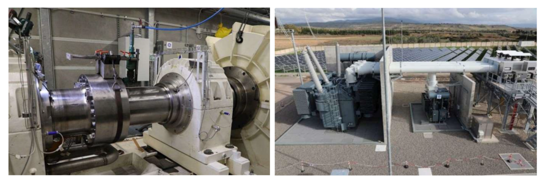
Figure 1 - Terna Synchronous Condenser installed in the Italian Grid
2. Technology and characteristics of the new Terna's unified synchronous condenser / flywheel systems
To cope with the network strength (both inertia and short circuit) reduction, Terna begun in 2014 an installation plan for synchronous condensers. The first two units, each with a 250 Mvar rating, were installed in 2014 in the islanded network of Sardinia, enhancing the operation of the existing multi-terminal, multi-infeed HVDC systems [12]; following the first installation successful installation, Terna decided to extend the project and to standardize the main characteristics of the synchronous condensers, aiming at:
- Reducing procurement time and costs by using framework agreements
- Reduced design, delivery, testing and installation time, due to an unified design
- Enable multi-vendor procurement strategy
- Enable a simpler management for the main spare parts (most notably, step up and auxiliary load transformers), which are the same for all the plants
The new Terna’s synchronous condenser projects also include a flywheel system [13], which substantially increases the overall moment of inertia (from about 8750 kg m2 to over 35 000 kg m2) and the inertia constant (from about 1.75 s to over 7 s). The most significant innovation, compared to most synchronous condenser projects, consists in the flywheel, composed by the rotating body, rigidly coupled to the electrical machine rotor, the vacuum chamber and two external supports containing the bearings.
Most notably, the flywheel is enclosed in a vacuum-tight envelope [14], which allows for negligible (< 20 kW) windage losses.
The main characteristic of the new Terna’s unified synchronous condensers flywheel systems are reported in the following table.
| SC Rated power | 250 Mvar / -125 Mvar | Subtransient reactance | <12% (sat.) |
| Continuous overload | 290 Mvar | Rated speed | 3000 rpm |
| Temporary overload | 500 Mvar / 10 s | Total moment of inertia | 35 500 kg m² |
| Rated voltage | 19 kV | Primary cooling | TEWAC |
| Step-up rated power | 290 MVA | Step Up impedance | 12.5% (on a 290 MVA base) |
| SC Losses at full load (incl. aux. and flywheel) | <3 MW | Step Up efficiency | Ecodesign TIER II |
At present time, 7 synchronous condenser / flywheel system, each rated 250 Mvar, are in commercial operation in Matera, Foggia, Garigliano, Selargius, Fano, from 3 different manufacturers (Ansaldo, GE, Siemens), and other 9 are currently under commissioning.
Other 4 synchronous condenser without flywheel are in service in Codrongianos, Favara, Partinico.
At the end of 2022, a total number of 24 SCs, 20 of which with a flywheel, are expected to be in operation in the Italian Grid.
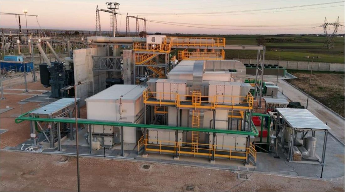
Figure 2 - Layout of the 2 x 250 Mvar synchronous condenser / flywheel system in Matera (SC, aux and flywheel manufactured by Ansaldo, Step-up Transformer manufactured by Getra, GCB and BOP manufactured by ABB, Flywheel cryogenic system manufactured by Criotec)
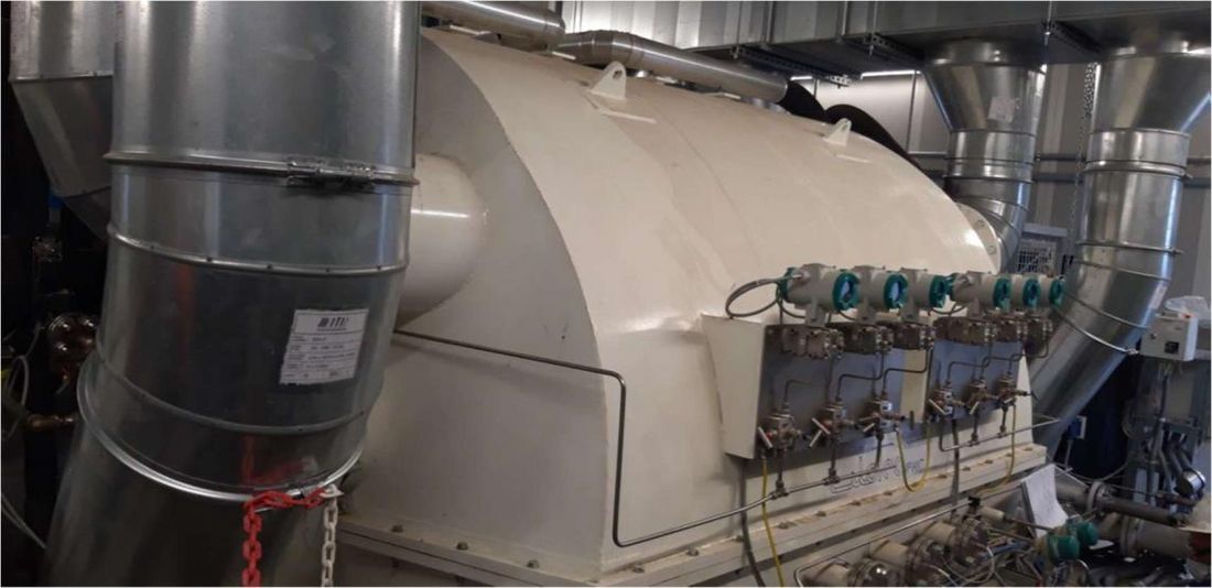
Figure 3 - Vacuum tight enclosure for the flywheel (Ansaldo / Criotec)
3. Synchronous condenser PSS tuning and testing
The modern power system consists of a large mixture of renewable energy sources (RES), varying and flexible loads, and is also experiencing a situation where a significant number of conventional generators are being replaced by power electronics-based sources. All of these factors may lead to a decrease in the small-signal stability margin of the system which in turn can cause power system instability. PSSs are widely used to improve the low-frequency oscillatory stability of power systems [12]. Moreover, including PSS in synchronous condensers the voltage regulator could be improved in order to cope with grid voltage variations and ensure greater stability during operation [13].
The Italian grid code, in the new version of the defense plan updated following the publication of Emergency & Restoration Network Regulation [14]; recommends the installation of PSS devices for generation groups of 50 MW or higher size; the PSS2B and PSS2C schemes according to IEEE std 421.05/2016 [15] must be adopted, the PSS4B scheme is also allowed in addition to one of the previous ones.
The precription sets forth the use of double input PSS (active power and frequency), as shown in Figure 4 and PSS settings are agreed with the Italian TSO either through periodically checked during power plant inspections and tests or through tests related to the upgrading of the excitation systems or PSS. This test consists in applying a step on the voltage reference of the synchronous generator Automatic Voltage Regulator (AVR) and collecting the active power response for successive assessment of the damping. As it can be noted by the Figure 5, the magnitude of the step is 2 % of the nominal voltage and the traces in red and blue represent the response with PSS disabled and the one with PSS enabled with parametrization designed by Terna, respectively.
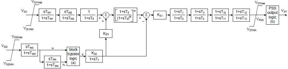
Figure 4 – PSS2C defined in std. IEEE 421.5-2016
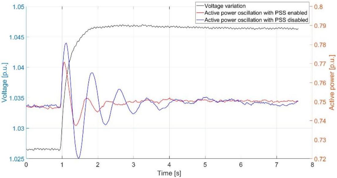
Figure 5 – Active power response to a voltage step with PSS enabled and disabled
It can be noted by the Figure 5 that with Terna finetuning the damping ratio of the excited oscillation mode is practically doubled: from 12.5 % without PSS to 23.6 % with PSS. PSS tries to compensate the phase shifting introduced by the excitation voltage that has an inherent unstable action on the synchronous generator electromagnetic torque. The goodness of its performance can be assessed by looking at the phase shifting between frequency and voltage imposed by the electrical machine on the typical frequency of the electromechanical oscillations. In Figure 6 the re-phasing action imposed by the PSS is well observable in the typical range of inter-area oscillations characterizing the ENTSOE CESA via the application of the Cross Power Spectral Density methodology (CPSD) [20-22].
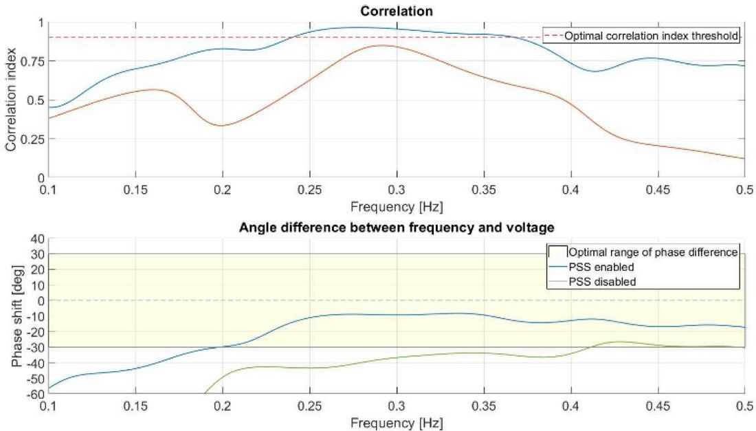
Figure 6 - Cross Power Spectral Density analysis on voltage and frequency measurements recorded during generator tests: comparison of results with and without PSS
Regarding the use of PSS in synchronous condensers, the input channel remains the only frequency channel while the power channel is strongly attenuated acting on PSS2B configuration parameters. The effectiveness of the PSS parameterization is tested by evaluating the phase shift between frequency and voltage only and not considering the damping ratio. In Figure 7 and the results of CPSD on tests carried out on a synchronous condenser without and with PSS, respectively, is shown. It can be noted the re-phasing action of PSS, in the range of low-frequency electromechanical oscillations, with a high level of correlation.
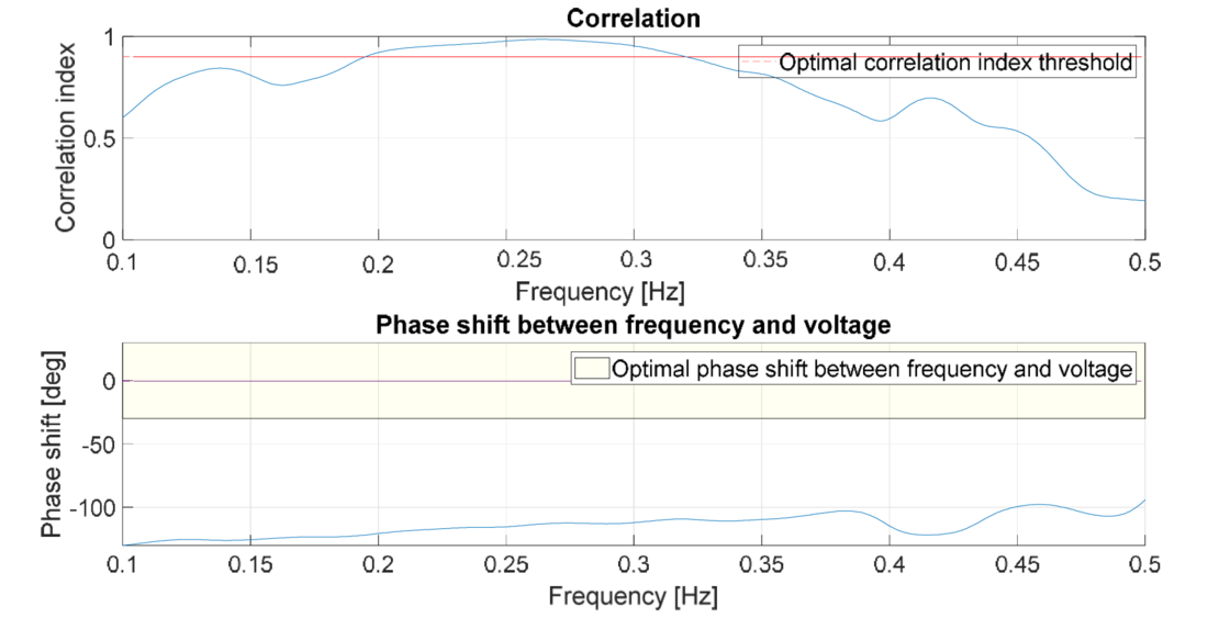
Figure 7 - Cross Power Spectral Density analysis on voltage and frequency measurements recorded during SCs tests: results with PSS disabled
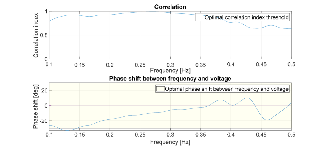
Figure 8 - Cross Power Spectral Density analysis on voltage and frequency measurements recorded during SCs tests: results with PSS enabled
4. WADC control implementation and testing on Terna SCS
The WADC architecture adopted for Terna project is described in Figure 9. This architecture uses a phasor data concentrator (PDC) collecting Phasor Measurement Unit (PMU) measurements, to feed the Supervisory Control with the data necessary to process the set point of the WADC system, carried out by the specific software developed in collaboration with EPRI. Through a fast protocol, the WADC sends the set point to the field devices, in this case a customized PMU acts as an interface with the excitation system of the synchronous condenser. Through appropriate implementations, the excitation system injects the signal into the Automatic Voltage Regulator (AVR), which controls the excitation of the synchronous machine and allows the actual implementation of the set point.
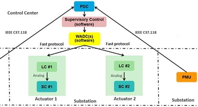
Figure 9 - WADC architecture adopted for Terna Project
The WADC is designed based on the system transfer function model represented in Figure 11. In Figure 10 it is schematically represented the operation of the WADC system and data exchange between central and local system.
A basic structure of the transfer function model of the controller is as shown in Figure 11. Figure 13 represents a block diagram of the WADC signal integration in the Excitation System of the Synchronous Condenser. The control command sent by WADC system is acquired by the modified PMU, which converts the digital command into an analog signal [4-20 mA]. Between the PMU and the excitation system is interposed a transducer, necessary to ensure the galvanic separation between the two systems. This transducer takes a current signal as input and provides a current and voltage output. In the solutions adopted by the suppliers of the excitation system, the voltage solution is usually preferred. The WADC set point is inserted into the AVR block diagram as shown in the Figure 13. The analog signal is processed by the control system only if the WADC command is active. This command is defined by the WADC system and sent to the excitation system, via the PMU, as a digital signal. As it can be seen from the block diagram, the WADC set point is added to the other contributions (e.g. reference voltage, PSS output, etc.). Wherever possible, this signal is inserted downstream of the overexcitation and underexcitation limits, so that it is present even when these limits are applied as a replacement and not as a sum of the other contributions.
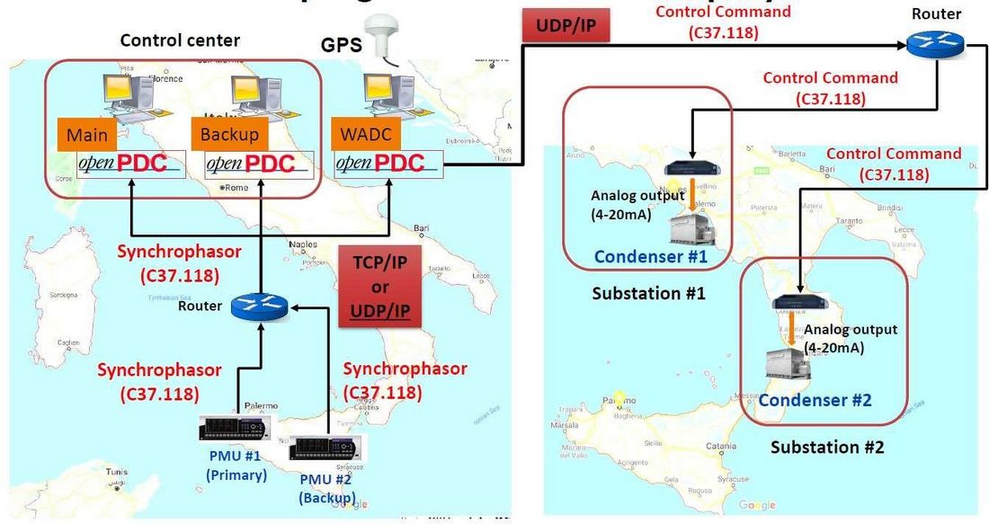
Figure 10 - Schematic overview of the WADC system communication between center and local devices
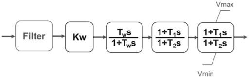
Figure 11 - WADC transfer function
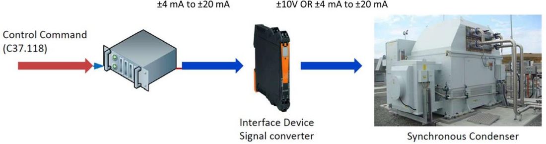
Figure 12 - WADC analog signal integration on SCs Excitation System
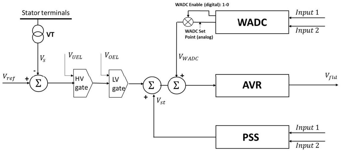
Figure 13 – Example of WADC integration scheme in the Excitation System of SC
Field testing of the WADC system, using recently installed synchronous condensers in the Italian network, is planned during 2022. For this purpose, the excitation systems of some SCs have been suitably prepared for the reception and implementation of the WADC set point. Field tests will have as first objective to verify the correct communication between the central WADC system and the apparatus placed in the premises of the synchronous condenser. These communications shall take place with adequate performances in terms of latency and reliability, in compliance with the characteristics specified in the design phase. The interfacing between the PMU and the SC excitation system will also be tested, verifying the correct exchange of digital and analog signals. It will be also verified the correct implementation of the modifications made to the excitation system (specifically to the AVR). From the point of view of the electrical system, the tests will verify the impact of the WADC set-point on the electrical quantities. As the activities progress and the system is installed on a larger number of SCs, the impact of the WADC will be further investigated and it will be possible to better appreciate its contribution on the grid stability.
5. Conclusions and future work
Further installations of synchronous condensers in the Italian network are planned during 2022. During the commissioning phases, as done for the previous installations and briefly described in the specific paragraph, the PSS functionality will be properly calibrated and tested. WADC system tests will also be carried out on some recently installed systems, in order to verify the correct functioning and performance of a newly designed oscillation control system for the Italian network. It will therefore be possible, by means of real data, to have a field test of the potential of this system, with the possibility also to identify possible improvements.
References
- P. Kundur, Power System Stability and Control, New York, NY, USA: McGraw Hill, 1994.
- System Protection and Dynamics WG, «Oscillation Event 03.12.2017, » March 2018.
- Y. M. a. K. T. Y. Katsuya, «Power system stabilization by synchronous condenser with fast excitation control, » in PowerCon 2000. 2000 International Conference on Power System Technology. Proceedings (Cat. No.00EX409), Perth, WA, Australia, 2000.
- L. Michi, E. M. Carlini, G. Giannuzzi, R. Zaottini e C. Pisani, «Improving dynamic stability in presence of static generation: issues and potential countermeasures,» in 2019 AEIT International Annual Conference (AEIT), Florence, Italy, 2019.
- S. Kamalasadan, G. D. Swann e R. Yousefian, «A Novel System-Centric Intelligent Adaptive Control Architecture for Power System Stabilizer Based on Adaptive Neural Networks,» IEEE Systems Journal, vol. 8, n. 4, pp. 1074 - 1085, 2013.
- I. Kamwa, R. Grondin e Y. Hebert, «Wide-area measurement based stabilizing control of large power systems-a decentralized/hierarchical approach,» IEEE Transactions on Power Systems, vol. 16, n. 1, 2001.
- X. Xie, J. Xiao e C. Lu, «Wide-Area stability control for damping interarea oscillations of interconnected power systems,» IET Proceedings - Generation Transmission and Distribution, pp. 507- 514, 2006.
- L. Zhu, R. Liu, Z. Pan, Y. Liu, E. Farantatos, M. Patel, S. McGuinness e N. Bhatt, «Adaptive wide-area damping control using measurement-driven model considering random time delay and data packet loss, » in 2016 IEEE Power and Energy Society General Meeting (PESGM), Boston, MA, USA, 17-21 July 2016.
- L. Zhu, Y. Zhao, Y. Liu, E. Farantatos, M. Patel, P. Dattaray, D. Ramasubramanian3, L. Michi, E. Carlini, G. Giannuzzi e R. Zaottini, «Oscillation Damping Controller Design Using Ringdown Measurements for the Italian Power Grid,» in 2019 IEEE Milan PowerTech, Milan, Italy, 23-27 June 2019.
- L. Zhu, C. Zhang, Y. Zhao, H. Xiao, I. Altarjami, Y. Liu, E. Farantatos, M. Patel, C. Pisani, G. Giannuzzi e R. Zaottini, «Mitigating Inter-Area Oscillations Using Adaptive Wide-Area Damping Controller Based on Measurement-Driven Model: Case Studies on Realistic Grid Models and Actual Events,» in CIGRE Paris Session 2020, ref. C2-101_2020.
- C. Zhang, Y. Zhao, L. Zhu, Y. Liu, E. Farantatos, M. Patel, H. Hooshyar, C. Pisani, R. Zaottini e G. Giannuzzi, «Implementation and Hardware-In-the-Loop Testing of A Wide-Area Damping Controller Based on Measurement-Driven Models,» in 2021 IEEE Power & Energy Society General Meeting (PESGM), 2021.
- A. D. Giulio, G. Giannuzzi, V.Iuliani, F. Palone, M. Rebolini e S.Zunino, «Increased grid performance using synchronous condensers in multi in-feed multi-terminal HVDC System,» in CIGRE 2014 session, paper A1-112, Paris, 24-29th August 2014.
- F. Palone, F. Gatta, A. Geri, S. Lauria e M. Maccioni, «New synchronous condenser - Flywheel systems for a decarbonized sardinian power system,» in IEEE PowerTech 2019, Milan (Italy), 23-27 June 2019..
- L. Buono, G. Gemelli, F. Palone, F. Pepe, A. Valant, A. Raciti, M. Schenone, G. Roveta, A. Stiger, L. Callegari, L. Negri e M. Rebolini, «Technical challenges and solutions for the new Terna’s standardized synchronous condensers/flywheel,» in CIGRE 2020 Session paper A1-304, Paris, August 2020.
- L. Zhu, H. Liu, Y. Ma, E. Farantatos, Y. Liu , M. Patel e S. McGuinness, «Adaptive and coordinated oscillation damping control using measurement-driven approach,» in 2016 Power Systems Computation Conference (PSCC), Genoa, Italy, 20-24 June 2016.
- A. V. Oppenheim, R. W. Schafer e J. R. Buck, . Discrete-Time Signal Processing. 2nd Ed, Upper Saddle River, NJ: Prentice Hall, 1999.
- L. R. Rabiner e B. Gold, in Theory and Application of Digital Signal Processing, Englewood Cliffs, NJ, Prentice-Hall, 1975, pp. 414-419.
- P. D. Welch, «The Use of the Fast Fourier Transform for the Estimation of Power Spectra: A Method Based on Time Averaging Over Short, Modified Periodograms,» IEEE Transactions on Audio and Electroacoustics, Vol. %1 di %2AU-15, pp. 70-73, June 1967.