B5 - Defining an MV/LV Protection, Automation, and Control system based on 5G network
Authors
M.O. NAIT BELAID - EDF R&D, Gustave Eiffel University, France
V. AUDEBERT, B. DENEUVILLE - EDF R&D, France
R. LANGAR - Gustave Eiffel University, France

Summary
In this paper, we first highlight the issues the distribution network will undergo when the rate of Distributed Energy Resources (DER) will increase in the electrical system. The development of MV and LV DERs might also increase the number of unwanted islanding situations of MV network portions, leading to human risks, creating uncleared faults, and preventing automatic reclosure. Furthermore, power network operators are seeking to improve their network availability where efficient protection systems and accurate fault location are key success factors.
Next, we study the latest cellular network technologies in connection with distribution grid protection and automation applications. Such applications call for highly reliable, secure, and low-latency communication services that are commonly based on wired communication technologies. These technologies are usually expensive and difficult to apply to electric networks covering a wide area with many connection points. The deployment of 5G, along with emerging Information and Communication Technologies (ICT) and standards, improved reliability and interoperability, as well as low latency communication capability, will allow the implementation of new advanced applications while keeping the total deployment costs low.
Then, we present a new 5G-based architecture for new Protection, Automation, and Control (PAC) and Fault Location, Isolation, and Service Recovery (FLISR) schemes. The aim behind this architecture, based on wide area measurement and monitoring system, is to protect the power network against disturbances that are beyond the scope of conventional protection schemes. Finally, we evaluate the effectiveness of our solution using a 5G-based experimental prototype.
Keywords
Distributed Generators - Renewable Energy - Protection Scheme - Wide Area Protection System - FLISR - 5G1. Introduction
Power systems are experiencing drastic changes with the introduction of Distributed Generators and Customer-Owned Resources (DGCORs), such as Photovoltaics (PVs), wind turbines and batteries, connected on MV and LV networks. Also, Synchronous Generators (SGs) are gradually replaced by Inverter Based Generators (IBGs). Compared to SGs, IBGs provide more limited fault current because of power electronics components limitations. SGs may provide fault currents of 5 to 7 times the rated current, while IBGs usually only provide 1 to 1.2 times the rated current. At HV level, this impacts the Short Circuit Powers (SCPs) of the networks and introduces stabilities issues. At MV and LV levels, DER development may lead to issues such as protection relay blinding and unwanted islanding.
Until now, the possibility of bulk DER integration was not considered during protection scheme design. Indeed, conventional design assumes: i)The SCP is sufficiently high to ensure the operation of all HV, MV, and LV protections; ii) The power system is sufficiently stable to allow fault clearance at each voltage level; iii) Most of the generators are connected at HV level, so short-circuit current in MV and LV levels are unidirectional; iv) There is a very low risk of unwanted islanding situation of MV and LV feeders; v) The loss of production in MV and LV levels in the event of an HV fault remains very small.
The aforementioned considerations were discussed in many articles through multiple studies. Article [1] highlights the issues coming along with the changes in the distribution network. It presents an overview of the major blackouts around the globe, while focusing on the initial disturbance and the cascading events. Based on HV and MV fault simulations, in our previous articles [2] and [3], we highlighted the changes in the power system and their impact on distribution network.
In 2019, several cascading events, triggered by a fault in the HV level, led to unwanted tripping of DER decoupling protections. This event resulted in the disconnection of approximately 1,1 million customers around London [4]. The use of connectivity and automation shall mitigate the risk of the occurrence of such blackout events and provide new opportunities for DSOs. Communication technologies are classified into two classes: wired and wireless. Presently, wireless communications are preferred to wired communications, the latter fit the PAC communication requirements but can be expensive and difficult to deploy and maintain over the whole area covered by electric networks already in place. In [5], the authors presented the grid automation state in Sweden, and the opportunities that 5G technology can bring to it. The current cost of interruptions is estimated at around 150 million euro per year. With the use of information communication technologies (ICT) such as 5G, interruption durations are expected to be reduced by 50%-75% resulting in a revenue increase for the distribution system operator (DSO) of up to 40 million euro per year. Compared to other wireless technologies, 5G offers several advantages, it can serve multiple applications with different communication requirements (i.e. latency, throughput, density, power efficiency, etc.), which contributes to greater flexibility, scalability, and interoperability. According to [6], only 24% of utilities manage just one communications network, with 58% of utilities have between 2 to 6 operating networks, 14% between 7 to 10, and 4% have 10 or more networks, with a significant complexity and financial burden to manage. 5G proposes 3 application scenarios, namely: Enhanced Mobile Broadband (eMBB), Ultra-reliable and Low Latency Communications (URLLC), and Massive Machine-type Communications (mMTC) as shown in Figure 1 from [7].
In this paper, we first highlight the aforementioned issues. Then, we present a new 5G-based PAC approach to cope with these issues based on an edge computing architecture which is able to: i) host control, protection and FLISR functions; ii) carry out real-time measurements; and iii) ensure information exchange with distributed sensors, protection relays, and DGCORs. Such schemes can considerably improve the electric power system resilience by reducing islanding risks while avoiding unwanted disconnections. Moreover, this architecture can accelerate FLISR execution. We also discuss the need of back-up protections based on local measurements and cybersecurity safeguard systems. Finally, we evaluate the effectiveness of our solution using a 5G-based self-healing experimental prototype that replicates the sequence of actions performed during a fault. The prototype uses off-the-shelf components like protection equipment and fault passage indicators (FPIs), as well as a Real-Time Hardware-in-the-Loop testing platform where we simulate the grid dynamic behavior during HV or MV grid faults. In the test scenarios, all DERs are connected to the MV distribution network. The results achieved with our test bed show that the proposed PAC solution meets the strict technical constraints required to clear all the use cases we considered and keeps the total deployment costs low.
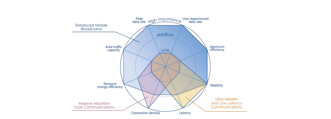
Figure 1 - The expected requirements for 5G application-types
2. Impact of DERS on the protection systems of MV and LV networks
DG integration into distribution networks affects the requirements and the performance of MV and LV conventional protection schemes. The main protection issues under these conditions are presented in [8], [9], and our previous articles [2] and [3] where we considered the following issues: i) Nuisance or false tripping of protection relays; ii) Protection blinding; iii) Recloser-fuse coordination; iv) Unwanted islanding of feeders; v) Unwanted disconnection of DER during HV faults or wide area disturbance.
In this article, we focus on the 2 last issues and demonstrate how 5G-based communication can contribute to handle it through a remote decoupling mechanism.
2.1. Unwanted islanding
According to IEC 62116 standard [10], islanding corresponds to a situation in which a portion of the power network, containing customers and producers, is isolated from the main grid. An unintentional island can be created when a segment of the utility grid containing only customer-owned generations and loads is isolated from the utility control.
Normally, when a segment of the MV grid is disconnected from the upstream grid, DERs (PVs or wind turbines) connected to that segment must stop supplying the grid. However, the load and the power produced on this portion of the grid may be balanced prior to the isolation event, i.e. the production is approximately equal to the consumption. In this case, when the source substation circuit breaker is opened (e.g. following a fault or a manual operation in the feeder), the network portion separated from the upstream network remains energized. It forms an island supplied by DER in grid-following mode (highlighted in green in Figure 2). Its voltage and frequency become unstable, varying according to changes in production and consumption. With the development of DERs and self-consumption, the probability of creating unintentional islanding will increase. Islanding operation may cause damages and present various kinds of dangers:
- Failure in eliminating a temporary fault (arc extinction) when DERs continue to feed the fault in an unwanted islanding situation. This will prevent the reclosing and convert a temporary fault into a permanent one.
- Failure in eliminating a permanent fault : a fault can be fed during an islanding situation with no mean to clear it, because it is located on the public network, or because unintentional islands provide a fault current less than needed to operate fuses or overcurrent relay protection devices inside the island.
- Reclosing issue : if there is no voltage check and the reclosing is performed before the interruption of unintentional islanding by anti-islanding protections, two asynchronous operating systems will be coupled (i.e. out of phase reclosing), which could lead to serious material damage. With voltage check, the reclosing cycle will be interrupted which will lead to a long shutdown.
- Utility line workers will be at risk if they think that the line is off.
- Power quality issues: as the unintentional islanding zone may operate under power conditions that are not suitable for the loads.
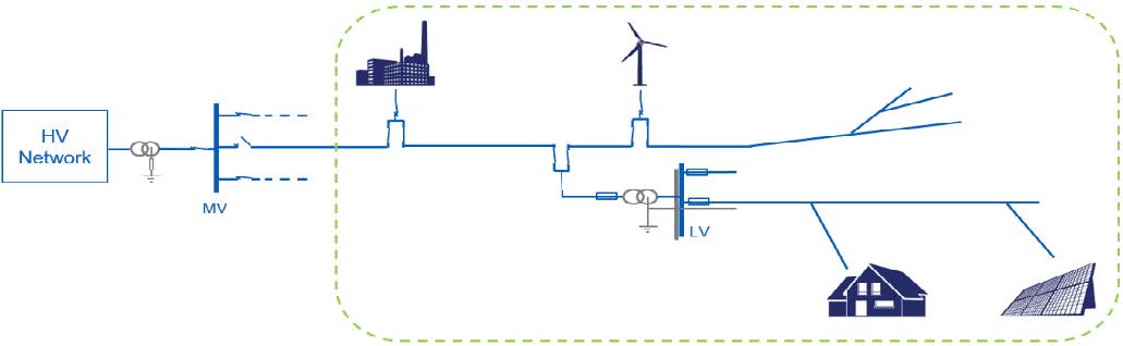
Figure 2 - Example of unwanted islanding situation
Electricity production installations are equipped with decoupling protection intended to disconnect distributed generators in the event of an incident preventing unwanted islanding. To do so, protection relays compare voltage and frequency measurements to thresholds, if the measurements are outside the authorized range, the protection trips according to the time delay associated with the threshold. Depending on the context, the settings of these protections may change. If the MV grid voltage or frequency changes following an HV fault, untimely DER disconnections may appear.
2.2. Remote decoupling
To minimize both MV feeder islanding and untimely DER disconnection (following HV faults) risks, one of the solutions is remote DER decoupling as shown in Figure 3, large voltage and frequency ranges are set to avoid untimely disconnections, but the substation sends a decoupling order to the DER when the feeder circuit breaker opens. Currently in France, remote decoupling is carried out for producers whose production is greater than 5 MW, a wired link is installed between the DER and its MV substation.
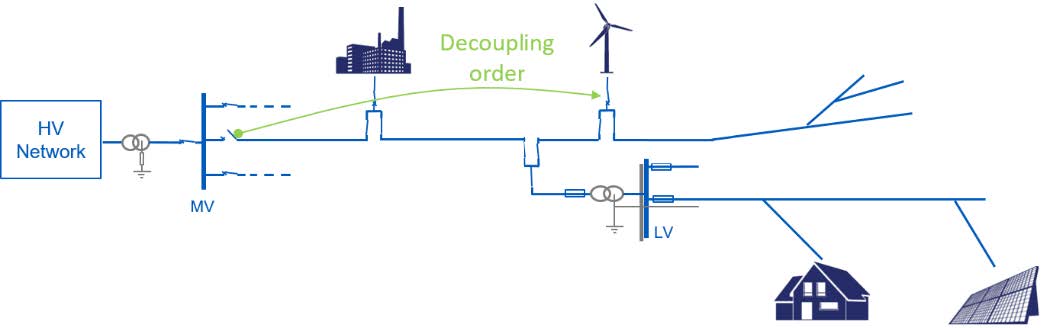
Figure 3 – Illustration of remote DER decoupling system
3. 5G-based FLISR architecture
Evolving cellular networks have the potential to provide flexibility, redundancy, and cost-efficiency in particular in retrofit cases, eg: when communication layer is annexed to an existing distribution grid. In the conducted work, we leverage the use of new communication capability provided by 5G and edge computing to set up a three-level based FLISR architecture, which enhances the operation of the protection scheme. In these applications, the number of devices is limited, and data amounts are relatively small, but latency, jitter, and reliability requirements are extremely strict.
3.1. 5G status
Operators have taken different strategies to exploit 5G technology. For the transition from 4G to 5G, 3GPPP has specified different deployment options [11] presented in Figure 4, most of the mobile operators have selected non-standalone (NSA) option 3x as their early 5G deployment since it allows fast deployment and effective use of existing 4G technology, it reuses the current evolved packet Core EPC and LTE base stations as the anchor for 5G. In this kind of deployment, the operators are focusing on offering full-service coverage in urban city areas. This strategy is consumer driven, targeted to offer high throughput, and eMBB by leveraging the use of carrier wider 5G frequency bandwidth, carrier aggregation (CA) and dual connectivity (DC). Some of the operators have selected option 2 or standalone option (SA) to keep 4G and 5G separate to offer dedicated private network services especially for industries. Operators that adopted this kind of deployment are concentrating on providing hotspots for private 5G networks for industrial use cases by covering smaller geographical areas. It is estimated that there will be over a million private networks in Europe by 2030 [12].
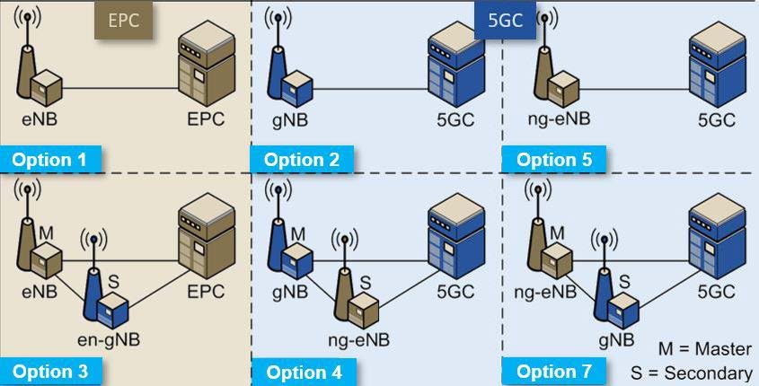
Figure 4 - Deployment options for 5G
Private networks offer to industries the possibility to parametrize the network, this come with need to understand how 5G works in order to utilize its full performance. 5G SA focuses on exploiting full 5G performance instead of the aggregated performance of 4G and 5G. this has a significant impact on latency sensitive use cases.
In our 5G test network we have utilized Option 3x, in this kind of configuration, user data traffic will flow directly through the NR (gNB) and then will be delivered over the air to the mobile device. A part of data can be also transmitted through the X2 interface to the LTE eNB and from there to the UE. Slow data flows can be delivered directly from the core of the network through 4G LTE.
3.2. Control approaches
In literature, many FLISR approaches were proposed: as discussed in article [13], they can be categorized as centralized, decentralized, or distributed. An efficient and appropriate communication architecture is needed for each approach.
3.2.1. Centralized architecture
In centralized FLISR, the data gathered from power network devices is stored and processed at a central location. The concentrated data is used for analytics and visualization. The resulted actions are then passed to the network components through communication links.
3.2.2. Decentralized or Flat Architecture
In decentralized FLISR, the controlled area is split into small regions, each region having its own local controller that performs independently from other region controllers. The power network devices of a specific region send data to the local controller, to store and analyze them. Orders are sent back to the power network devices of the region if they must perform local actions. The local controllers of each region exchange data between them if it is necessary to solve a larger area problem. The coordination between local controllers to solve large area problems is often very challenging to perform.
3.2.3. Distributed or Multi-level Architecture
Distributed FLISR scheme can be mapped between centralized and decentralized architectures. It includes local controllers as well as central or master controller. It can be thought of as centralized control with decentralized execution stage.
3.3. Proposed FLISR
An efficient FLISR system enhances the reliability and quality of supply of the power network by maximizing restored loads and reducing the outage duration [14]. The proposed FLISR shows the sequence of actions carried out when a fault occurs on the electric network. This includes 6 functions detailed below.
The aim of the communication network infrastructure is to meet each function resource requirements. The architecture we propose uses a distributed approach.
3.3.1. Defined FLISR functions
The proposed FLISR scheme contains 6 functions defined as follows:
- Fault detection: When a fault occurs, the feeder protection relay trips and opens the Feeder Circuit Breaker (FCB), for example if the current exceeds a predefined threshold. FCB and FPIs located along the network inform feeder controller about the fault through their communication link. At this stage, the faulty feeder is de-energized.
- Remote decoupling: Sending a multicast decoupling signal to all DERs anti-islanding protection relays after the FCB opening.
- Fault location: The feeder controller uses data collected from power network components (FPI, FCB, switches, etc.) as inputs for fault location algorithms.
- Fault Isolation: After an accurate location, the faulty section of the network is isolated from both directions by opening the closest upstream and downstream switches to the fault. As soon as the fault is isolated, the FCB closes and upstream out-of-service loads are restored.
- Power network reconfiguration: The target of DSOs is to reconnect as many customers as possible, while carrying out the minimum number of operations on network elements (i.e. sectionalizers and tie switches) within the shortest delay. The substation controller evaluates whether out-of-service loads can be transferred totally or partially to a healthy feeder. If the latter can recover part of the out-of-service loads, all the DERs present in that part must be managed by the controller to which the healthy feeder is connected, thus the remote decoupling link is maintained.
- Service Restoration: After the fault is cleared and the faulty section is repaired, a reverse sequence of operations is performed so that the distribution network returns to its normal pre-set configuration.
3.3.2. Level of deployment
With a fine-grained use case-oriented approach, the deployment of the proposed FLISR functions must follow a hierarchical organization [15]. This has various performance impacts, mainly on the latency and the level of situational awareness.
If the service latency requirement is not very strict, i.e. greater than 1 s, and the use case needs a global network operation, the application can be placed on a cloud level. However, if the application requires an end-to-end latency between 5 ms and 1 s with an operation scope centered on a single substation, the application must be deployed at the Mobile-Edge Computing (MEC) level. Protection functions based on distributed Intelligent Electronic Devices (IED) could be implemented at this level. Finally, if the provided service requires very low latency less than 5 ms, with a local operation scope, the application must be placed at the radio site, i.e. as close as possible to the power network components.
3.3.3. Architecture scheme
The conducted work proposes a flexible communication architecture based on edge computing capabilities, providing highly customized communication services according to diverse performance requirements demanded by FLISR schemes.
As presented in Figure 5, the proposed FLISR scheme consists of up to three levels. The lower level or local level is formed of electric network devices forming a wide area measurement system. The elements send data to a local controller placed in the middle level or edge level, which stores and analyzes them in order to send corrective orders to resolve local issues. Aggregated data is then sent to the central controller in the upper level or cloud level, which has a large snapshot of the system allowing to take in consideration a large number of parameters.
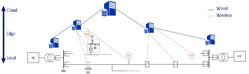
Figure 5 – FLISR: proposed three level architecture
3.3.4. 5G-based remote decoupling
As presented in Figure 6, using 5G network would allow, at the same time, to accommodate more decentralized generation plants with the remote decoupling mechanism, without installing additional infrastructure, such as wired connections. We expect that deployment and maintenance costs will be reduced.
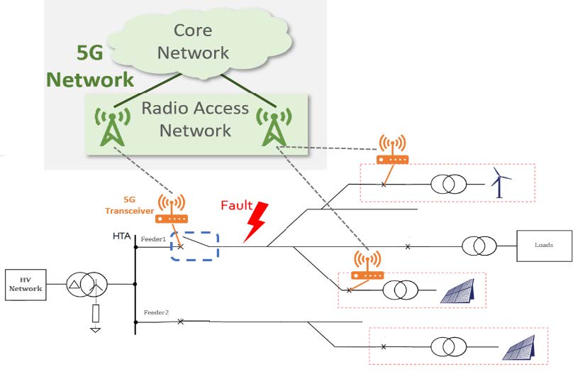
Figure 6 – Remote decoupling link using 5G infrastructure
3.4. Protection system resilience and cyber security
This article proposes a 5G network architecture that increases the performance of traditional protection systems and adapts them to new challenges associated with the evolution of the electric system. The improvement in performance lies in the speed of fault location and customers recovery. Adaptations to new issues associated with the evolution of the electric system concern:
- the adaptation of protections to system operation, and
- the capacity to keep the DERs connected when they are necessary for the system, or conversely to disconnect them if their presence endangers the safety of goods and people, or even risks disturbing network devices such as reclosers.
In such an architecture, it is important to ensure that each structure has a back-up protection system based on local voltage and current measurements, completely independent and isolated from the communication system. Therefore, in the event of failure in the 5G system, protection remains guaranteed with a reduced performance. In addition, cyber security issues will have to be addressed from the design phases of the solution. The communication system must be completely secure to prevent the power network devices units from being monitored during a cyber-attack.
4. Test setup and methodology
4.1. Experiment scheme
Currently in French distribution networks, only large DERs (> 5 MW) are equipped with anti-islanding protections embedding tele-protections functionalities. The anti-islanding protections of small DERs (≤ 5 MW) are only based on local voltage and frequency measurements. Using 5G-based communication architecture allows to extend remote decoupling to more MV and LV power plant, thus, strengthen the safety of the electrical system by limiting untimely disconnection of DERs, while considerably limiting the risks of unwanted islanding, which will promote DERs integration at MV and LV networks.
In order to implement the proposed FLISR, we design a prototype consisting of various off-the-shelf equipment such as protection components and FPIs, as well as a real-time hardware-in-the-loop testing platform where we simulate the grid dynamic behavior during HV or MV grid faults as shown in Figure 7, Figure 8, and Figure 9. The simulated distributed power network is connected to controllers hosted in the edge and cloud levels where the different FLISR functions are deployed. The communication link is based on our 5G test network. The prototype allows to collect data generated from the simulated power network and the connected protection components, then to process those data and take the most suitable actions i.e. sending commands to physical or simulated power components.
The protection equipment is directly connected to the real-time simulator through analog I/O. Two single-board computers (SBCs) are used as digital gateways, allowing physical and simulated protection equipment to communicate with the edge and cloud controllers. Our prototype is composed of three main layers:
First layer or the grid layer, which is composed of a real-time simulator with integrated Simulink model and a set of physical protection elements. The real-time simulator is connected to the physical equipment through analog or digital connections, the first are used to transfer currents and voltages of network, and the second are used to communicate the status of various components of the simulated network and receive control commands. Physical equipment contains a set of power protection components (protection relays, FPI).
The second layer consists of the communication layer which plays the role of interface between the grid layer and the control layer, it is composed of :
- Two single-board computers (SBCs) (2 X Raspberry Pi 3) that serve as a digital gateway to : i) Read the digital signals coming from physical or simulated power network components and send the contained data to the controllers in the control layer through a 5G link; ii) Receive the coming commands from the controllers (through a 5G link) and transform them to a digital signal that will be sent to physical or simulated power network components.
- 5G test network: it represents all the equipment that allows to transmit data between the digital gateway and the control layer.
Third layer is the control layer where the data processing is performed, and decisions are taken. This layer is composed of the local controllers, deployed in the MEC level, and the master controller, deployed in the cloud level. FLISR functions are deployed at two different levels (MEC, or Cloud), according to two key parameters: i) the required latency; ii) and the level of situational awareness or the amount of data required for the function to operate properly.
The role of local controllers is to analyze the collected data from the grid layer in order to send corrective orders to resolve local issues (i.e. FLISR functions 1,2,3 and 4: Fault detection, remote decoupling, fault location and isolation) in the same substation, whereas, master controller which has a large system snapshot, uses aggregated data collected from local controllers to solve wide area problems (i.e. FLISR functions 5 and 6: Network topology reconfiguration, system restoration).
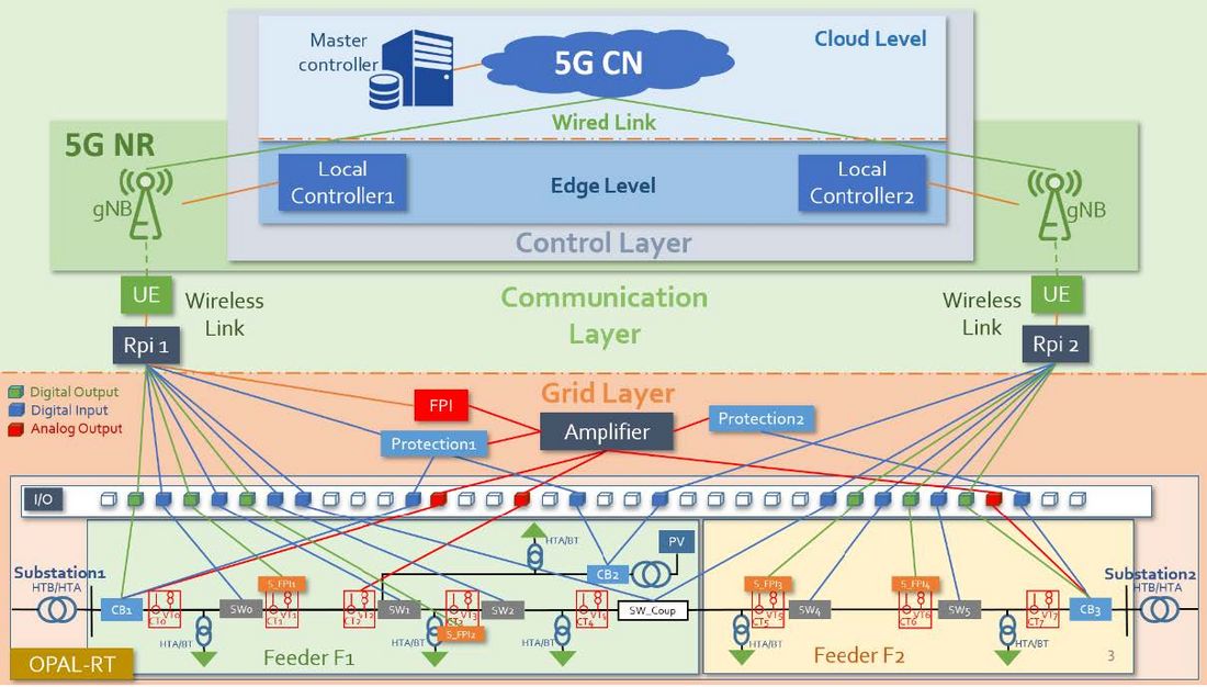
Figure 7 - Testbed architecture
4.1.1. Distribution network specification
The modeled distribution network is a semi-urban network with two 63/20 kV substations which are connected to each other with a coupling switch (SW_Coup). 65% of electrical circuits are underground and the rest are overhead. Power rating of each transformer is 36 MVA, neutral is connected to ground through 80 Ohm resistance. A 3 MW solar power plant (PV) is connected to the network (Feeder1 of substation1) by a circuit breaker. We considered Earth Fault Overcurrent Protection for the feeders of each substation, and a decoupling protection with islanding detection system (tele-decoupling) for the PV plant.
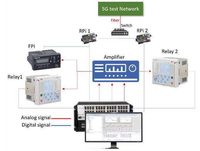
Figure 8 - Power components interconnection
4.1.2. 5G test network
The used 5G network is NSA compliant with 3GPP R15 December 2018. The 5G radio [16] operates in TDD band n78 (3500MHz) with a bandwidth of 20MHz.
The core is NSA core [17]. User equipment (UE) is a 5G router. The digital gateways are connected to the 5G router through an optical fiber cable.
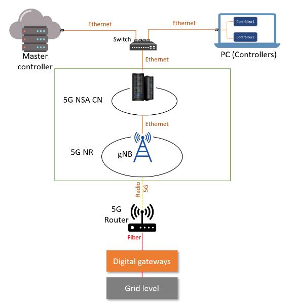
Figure 9 - 5G test network
4.2. Scenario
The scenario described below shows the sequence of actions performed during a fault, i.e. the fault detection, its location, its isolation, the reconfiguration of the distribution power network, and the service recovery. It consists of three phases:
4.2.1. Phase 1
Before the fault, the distribution network is in its normal operation mode, the first phase starts at t = 5 s:
- A ground fault appears between switches SW1 and SW2.
- Current and voltage transformers simulated in the feeder F1 send instantaneous current and voltage values from each part of the network to physical protection components. These signals are received from the analog outputs of the real-time simulator, amplified by the amplifier, and then transferred to the protection components (FPI and protection relays). At the same time, some of the simulated FPIs will detect the fault and send a digital signal to the Raspberry Pi1 using the digital outputs of the simulator.
- After detecting the fault in the feeder F1, a protection relay trips and sends a digital signal through the simulator digital inputs to open the circuit breaker CB1.
- The notification of the CB1 tripping as well as the notification of fault detection by the physical/simulated FPIs are sent to the Controller1.
- The Controller1 detects the occurrence of a fault in feeder F1 and notices CB1 tripping, so it sends a decoupling command to CB_PV (solar power plant circuit breaker).
- At the same time, the Controller1 analyzes the signals received from network FPIs and locates the fault.
- To isolate the fault, Controller1 sends digital signals through the simulator digital inputs to trip SW1 and SW2, which are respectively the closest upstream and downstream switches to the fault location.
- Controller1 sends closing command to CB1 in order to recover the upstream loads.
- After checking that the second substation can support the feeder F1 disconnected loads, the centralized controller perform network reconfiguration function, thus sends closing command to the coupling switch (SW3) so that the disconnected downstream loads will be re-energized by feeder F2.
- Controller2 sends closing command to CB_PV in order to recover a portion of downstream loads, consequently, all network sections, except the defective part, will be under voltage.
At the end of this phase, the topology of the power network will be modified, the solar power plant will be connected to feeder F2 instead of F1, thus it will be controlled by Controller2 instead of Controller1
4.2.2. Phase 2
- In this phase, an earth fault appears between switches SW4 and SW5 at t = 15 s. Controller 2 will follow the same steps as controller 1 in phase 1 to detect, locate and isolate the fault. In addition, as the PV plant is connected to station 2, controller 2 will send a remote decoupling command to CB_PV. Thanks to 5G communication, this level of flexibility is now possible, which is not the case in a conventional wired remote decoupling scheme.
- Controller2 sends closing command to CB2 in order to recover the upstream loads.
- After checking that the defective portion of network in feeder F1 was not repaired, the centralized controller will not perform network reconfiguration function.
After this second part of the scenario, a portion of the grid (between SW2 and SW5) still non-energized.
4.2.3. Phase 3
After repairing all the defective portions of the network, centralized controller will perform the recovery function which allows to the system to retrieve its initial configuration.
4.3. Results of the experiment
Using Matlab Simulink blocks, we measured the following delays:
- Average remote decoupling delay (Avg_RD_D): the delay between the opening FCB and CB_PV.
- Average fault location delay (Avg_FL_D): the delay between the fault detection (by the FPIs) and the execution of the fault location function by the local controller.
- Average fault isolation delay (Avg_FI_D): the delay between the fault detection and the opening of the closest upstream and downstream switches to the fault.
- Average network reconfiguration delay (Avg_NR_D): the delay between the fault detection and the execution of the power network reconfiguration function.
The Figure 10 shows the results obtained through the carried-out experiment.
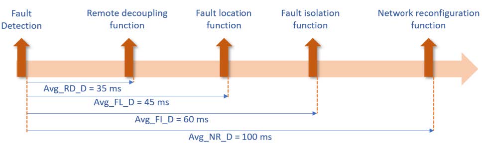
Figure 10 - results obtained from the experiment
The results showed high reliability of the 5G link with 100% of packets reaching their destination. The achieved Avg_RD_D is less than the maximum transmission time allowed by the French regulation [18] (i.e. < 70 ms). Regarding Avg_NR_D, it should be noted that the time of 100 ms is obtained in a very reduced configuration with two substations. We estimate that with the same architecture using a permanent 5G link in a real scale configuration (eg: with 50 substations), the average network reconfiguration delay will be reduced from few minutes to few seconds.
5. Conclusion
A 5G wide-area communication network has the potential to act as a key enabler for future smart grid applications. After having highlighted the challenges of the protection scheme in an evolving electric system, this article proposes a 5G-based FLISR scheme that increases the performance of traditional PAC systems and adapts them to new challenges. The proposed FLISR integrates a remote decoupling function, which maintains the remote decoupling link when the DER is connected to another feeder after a power network reconfiguration. Remote decoupling function fosters an increase in the penetration rate of DERs by providing solutions to identified constraints in the electrical system, such as, disconnection of DERs due to HV faults or a wide area disturbance. Moreover, as shown in the results section, the execution time of the proposed FLISR system will reduce the response time from few minutes to only few seconds, while allowing a seamless integration of DERs.
Next generation PAC schemes can leverage the use of 5G to become more efficient, faster, scalable, and less expensive. The advantage of 5G lies in the possibility to collect a huge amount of distributed data quickly with high reliability (i.e. uRLLC ), process it immediately (i.e. in the MEC) to analyze a disturbed network state; cases where conventional PAC schemes based on local measurements reach their limits. The performance of 5G will allow future PAC scheme to meet the requirements of multiple use cases without having to rely on different communication technologies.
We are currently working on 5G SA deployment within our laboratory, with the perspective to test the proposed FLISR scheme and compare its performance to the results obtained in this work. In addition, the implementation of the FLISR system will follow the micro-service framework by using virtual protection functions managed by an efficient orchestrator. This will simplify the deployment of protection schemes and ensure great flexibility and scalability while keeping the total deployment costs low. At the same time, we will carry out a cost-benefit analysis to quantify the impact of FLISR based on 5G SA and conduct a performance tests in the case of communication data loss, strong noise interference, or cyber-attack.
References
- H. Haes Alhelou, M. E. Hamedani-Golshan, T. C. Njenda, and P. Siano, “A survey on power system blackout and cascading events: Research motivations and challenges,” Energies, vol. 12, no. 4, p. 682, 2019.
- V. Costan, V. Gabrion, and B. Deneuville, “Power systems with massive insertion of distributed resources: impacts on distribution grids,” CIRED Conference, 2021.
- M. O. NAIT BELAID, V. AUDEBERT, V. COSTAN, and B. DENEUVILLE, “Defining a Wide Area Protection System Using 5G Communication Technology,” GCC Conference, 2021.
- N. ESO, “Technical report on the events of 9 august 2019,” Natl. Grid ESO, 2019.
- “Bringing 5G to power,” Mar. 18, 2020. https://www.ericsson.com/en/reports-and-papers/industrylab/reports/bringing-5g-to-power (accessed Jun. 29, 2021).
- L. Helen, T. Zahariadis, L. Sarakis, E. Tsampasis, A. Voulkidis, and T. Velivasaki, Smart Grid: a demanding use case for 5G technologies. 2018, p. 220. doi: 10.1109/PERCOMW.2018.8480296.
- S. Dahmen-Lhuissier, “ETSI - Mobile Technologies - 5g, 5g Specs | Future Technology,” ETSI. https://www.etsi.org/technologies/5g (accessed Apr. 17, 2022).
- V. Telukunta, J. Pradhan, A. Agrawal, M. Singh, and S. G. Srivani, “Protection challenges under bulk penetration of renewable energy resources in power systems: A review,” CSEE J. Power Energy Syst., vol. 3, no. 4, pp. 365–379, 2017.
- M. H. Bollen and F. Hassan, Integration of distributed generation in the power system, vol. 80. John wiley & sons, 2011.
- International Electrotechnical Commission, International Electrotechnical Commission, and Technical Committee 82 : Solar photovoltaic energy systems, Utility-interconnected photovoltaic inverters: test procedure of islanding prevention measures. 2014.
- arvindpdmn, “5G Deployment Options,” Devopedia, Dec. 30, 2020. https://devopedia.org/5g-deployment-options (accessed Dec. 13, 2021).
- J. Blackman, “A million private 5G networks by 2030? A million just in Europe, says Vodafone,” Enterprise IoT Insights, Jan. 27, 2021. https://enterpriseiotinsights.com/20210127/channels/news/million-private-5g-networks-in-europe-vodafone (accessed Dec. 11, 2021).
- R. Gore and M. Kande, “Analysis of wide area monitoring system architectures,” in 2015 IEEE International Conference on Industrial Technology (ICIT), 2015, pp. 1269–1274.
- A. Zidan et al., “Fault Detection, Isolation, and Service Restoration in Distribution Systems: State-of-the-Art and Future Trends,” IEEE Trans. Smart Grid, vol. 8, no. 5, pp. 2170–2185, Sep. 2017, doi: 10.1109/TSG.2016.2517620.
- S. E. Elayoubi, S. B. Jemaa, Z. Altman, and A. Galindo-Serrano, “5G RAN Slicing for Verticals: Enablers and Challenges,” IEEE Commun. Mag., vol. 57, no. 1, pp. 28–34, Jan. 2019, doi: 10.1109/MCOM.2018.1701319.
- “AMARI Callbox Series,” Amarisoft. https://www.amarisoft.com/products/test-measurements/amari-lte-callbox/ (accessed Dec. 27, 2021).
- “Dome | b-com.” https://b-com.com/en/accelerate/dome (accessed Dec. 27, 2021).
- Enedis, “Enedis-NOI-RES_13E.” Jun. 26, 2020. Accessed: Dec. 28, 2021. [Online]. Available: https://www.enedis.fr/sites/default/files/Enedis-NOI-RES_13E.pdf