A3 - Application of SF6 Alternatives for Retro-filling Existing Equipment
Authors
L. LOIZOU, L. CHEN, Q. LIU - The University of Manchester, United Kingdom
M. WALDRON, G. WILSON - National Grid Electricity Transmission, Warwick, United Kingdom
J. OWENS - 3M Company, St. Paul, Minnesota, USA

Summary
Sulphur hexafluoride (SF6) is a gas which has been widely used in gas insulated switchgear (GIS), lines (GIL) and busbars (GIB) as an interruption and insulation medium since the 1960s. The environmental concerns regarding SF6 usage, the most potent greenhouse gas known, have motivated researchers to find a more environmentally sound alternative as a replacement for SF6. While most of current research focuses on developing state-of-the-art high voltage (HV) equipment specifically designed for alternative gases, this work investigates the feasibility of retro-filling existing SF6-designed equipment. This is a more economic and time-saving solution to phase out the usage of SF6 for the power industry. The first step towards the development of a retro-fill solution is to trial various SF6 alternatives with the specific aim of identifying a suitable mixture combination for use in existing gas insulated assets.
A reduced-scale coaxial prototype was developed to determine a technically feasible gas mixture that can match the breakdown performance of SF6 under standard lightning impulse voltage waveform (1.2/50 μs). Breakdown results demonstrate that a 20% C3F7CN and 80% CO2 gas mixture exhibits comparable insulation capability to SF6 in coaxial geometries with similar field uniformity as found in GIL/GIB. A full-scale SF6 -designed 420/550 kV rated gas insulated demonstrator was assembled and retro-filled with a 20% C3F7CN and 80% CO2 gas mixture. The demonstrator was type tested under Switching Impulse (SI), Lightning Impulse (LI) and Power Frequency (AC) voltages in accordance with IEC 62271-204. Type test results have shown that the gas mixture can pass the withstand voltage tests at the specified voltage levels for SF6 gas under similar operating conditions. This work has demonstrated that a mixture of 20% C3F7CN and 80% CO2 could be a viable candidate for replacing SF6 in HV insulation applications without the need for changing the operating conditions (i.e. rated pressure) of the equipment. This is an encouraging step towards the potential phase out of SF6 in passive components installed across the transmission and distribution networks in the UK.
Keywords
Heptafluoro-iso-butyronitrile (C3F7CN / C4F7N / (CF3)2-CF-CN) - Sulfur Hexafluoride (SF6) - High Voltage - Gas Insulated Lines and Busbars - Electrical Breakdown - Type Test1. Introduction
Greenhouse gas emissions generated by human activities are a key contributing factor towards climate change. There is an increasing emphasis by the power industry to facilitate the transition to Net Zero. One key measure is the continued effort in the search for a more environmentally sound replacement of SF6 , a man-made gas with a global warming potential (GWP) 23,500 times greater than CO2 and a long atmospheric lifetime [1]. It is mainly used in gas insulated equipment across the transmission and distribution networks to provide dielectric insulation and arc interruption. The power industry presently accounts for 80% of the global SF6 inventory [2]. In the UK, it is estimated that the combined SF6 installed mass in the electricity network is approximately 1,500 t or 35 MtCO2e, with annual SF6 leak of 0.5 MtCO2e from 2015 to 2018 [3]. For National Grid Electricity Transmission (NGET), the majority of SF6 is used in passive components which are the focus of this investigation. Without viable alternatives, these figures will increase drastically in the coming decades as the electricity networks continue to phase out ageing air-blast and oil-insulated switchgear with compact SF6 equipment.
Recent SF6 -free installations use new equipment optimized by manufacturers for Novec™ 4710 and Novec™ 5110 insulating gases [4, 5]. While this is intended to reduce overall SF6 emissions, it requires considerable investment and replacing all existing SF6 -filled assets worldwide with new-builds is time consuming. An alternative approach and the aim of this study is to investigate the feasibility of retro-filling existing SF6 -filled passive components with alternative gases. This paper provides an overview of the SF6 replacement research work that has been carried out at The University of Manchester. The paper includes: (a) a review of SF6 alternatives; (b) insulation characteristics of SF6 alternatives tested for reduced-scale prototypes; (c) the development and validation of an industrial scaled gas insulated demonstrator designed for SF6 when the gas is replaced with a chosen gas candidate; and (d) IEC specified standard type test and non-standard type test results using the demonstrator.
2. Selection Process of SF6 Alternatives
Any new candidate must have a considerably lower GWP than SF6, but also satisfy a strict list of technical requirements such as high dielectric strength, good arc-quenching capability, low boiling point as well as being chemically stable, non-flammable, and low in toxicity. The aim of this work is to retro-fill existing SF6-designed transmission equipment. This means that the candidate must possess similar or better dielectric performance than SF6, but also be able to remain gaseous at the rated operating pressure of 4.5 bar [6]. Note that all pressures presented in this paper are in absolute value. Based on the literature, four promising fluorinated gases are shown in Table 1 and their merits are discussed in this section [1, 6-11]. One common limitation for all candidates is the comparatively higher boiling point than SF6. Therefore, these gases must be used in low proportions mixed with a carrier gas such as CO2 or N2 to avoid liquefaction at elevated pressures required for HV applications. Additionally, these fluorinated gases are denser than air. This means that there is a risk of asphyxiation should a substantial level of these gases be released and allowed to settle within an enclosed environment (i.e. indoor GIS).
| Gas Name | Dielectric strength relative to SF6 (pu) | Global Warming Potential | Boiling Temperature (°C) |
|---|---|---|---|
SF6 [1] | 1.0 | 23,500 | -63.8 |
CF3I, Trifluoroiodomethane [7, 8] | 1.2 | <5 | -22.5 |
C3H2F4, HFO-1234ze(E) [9] | 0.85 | 6 | -19.4 |
C5F10O, Novec 5110 [10] | 2.1 | <1 | 26.9 |
C3F7CN, Novec 4710 [6, 11] | 2.0 | 2,100 | -4.7 |
CF3I is a gas that is chemically inert, non-flammable and has a dielectric strength that is 1.2 times higher than that of SF6. The weak chemical bond C-I in CF3I means that it can be decomposed quickly in the atmosphere via photolysis, and thus has a low GWP [8]. Based on inhalation tests, the US National Research Council’s (NRC) committee on toxicology has recommended that CF3I has a lowest observed adverse level (LOAEL) on cardiac sensitization at 0.4% concentration [12]. The overall toxicity level of CF3I would drastically reduce when used as a mixture with either CO2 or N2. As for C3H2F4, commercially known as HFO1234ze(E), there are two key drawbacks: (i) the trade-off of dielectric strength (85% of SF6) and boiling point (-19 °C) means that its application is limited to medium voltage equipment operated close to atmospheric pressure, and (ii) the soot formation due to high energy discharge. Both CF3I and C3H2F4 gases generate solid precipitations (iodine and soot) that can pose an operational concern if they accumulate on a solid insulator, which could lead to surface flashover at a significantly reduced voltage [8, 9].
A unique “first breakdown” behavior has been reported for C3H2F4 [9]. The initial breakdown was subsequently followed by consecutive positive LI breakdowns chopped on the front of the LI waveform (<1 µs) as shown in Figure 1(a). The breakdown characteristic stabilizes after the first withstand is achieved. By using C3H2F4 in a mixture, the first breakdown effect is minimized indicating soot formation is the main cause of this behavior, which must be factored into any potential application of C3H2F4. Interestingly, if there is no breakdown occurrence, C3H2F4 possesses comparable dielectric performance as SF6 under non-uniform fields as demonstrated by the partial discharge (PD) characteristics shown in Figure 1(b) [9].
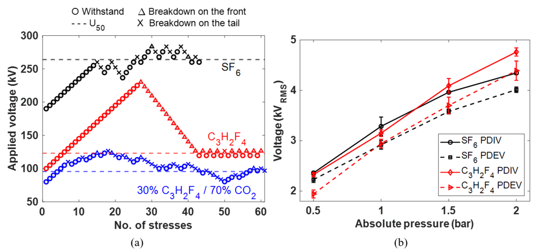
Figure 1 - (a) Test sequences for SF6, C3H2F4 and 30% C3H2F4 / 70% CO2 for LI(+) tested for a stainless steel 25 mm dia. hemisphere-to-plane configuration with a 10 mm gap and at 2 bar pressure, and (b) PDIV/EV characteristics for SF6 and C3H2F4, tested using a hemisphere-to-plane configuration with a 3 µm needle tip radius for pressures ranging from 0.5 to 2 bar [9]
C5F10O (Novec 5110) is a perfluoroketone gas and to remain gaseous in gas-insulated equipment rated at 4.5 bar, less than 10% of C5F10O may be used in a mixture. This would provide a C5F10O mixture that has considerably lower dielectric strength than SF6 at the same pressure and is unsuitable for retro-fill applications in HV equipment [10].
Novec 4710 is part of the fluoronitrile gas family, the formula C4F7N can exist in more than one isometric form: linear and branched. In its branched isometric form, the gas is practically non-toxic, which could be represented by the condensed formula (CF3)2CFCN. Note that the linear form CF3(CF2)2CN is toxic. Novec 4710 can contain a small amount of the linear isomer with the gas purity being >99.5%. C3F7CN is used to make clear that the molecule has a nitrile functionality with “CN” and thus is the preferred formula hereafter. C3F7CN has a much shorter atmospheric lifetime of 30 years and a GWP of about a tenth of SF6. The GWP of this gas is still reasonably high at 2,100 but with only 4 to 10% of C3F7CN used in mixtures. This represents a 99% carbon footprint reduction when compared to SF6 [5]. By adopting a 20% C3F7CN and 80% CO2 mixture, a comparable dielectric strength and a carbon footprint reduction of up to 98% of SF6 is achieved, while maintaining a low liquefaction temperature of -10 °C [6]. Note that carbon footprint reduction calculation is taking into account the different densities of C3F7CN/CO2 mixture and SF6 at the same pressure.
A coaxial configuration with a 10 mm outer dia. conductor and a 30 mm inner enclosure dia. that mimic the field uniformity as found in a GIL/GIB was used to compare the different gas candidates. Figure 2 shows that CF3I/CO2 mixtures [7, 8, 13] and C3H2F4 [9] possess the lowest breakdown performance for both LI polarities. Despite offering an extra liquefaction temperature margin of 5 ℃, the use of 16% C3F7CN / 84% CO2 mixture demonstrates a reduced dielectric strength, particularly under LI(-) which is the critical design voltage for GIL/GIB [11]. It is clear that a 20% C3F7CN / 80% CO2 mixture has similar breakdown strength as SF6 for coaxial geometries and is the preferred gas candidate in this retro-fill investigation [6].
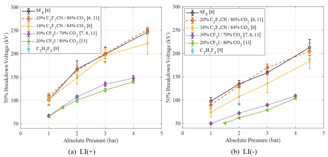
Figure 2 - Breakdown characteristics of SF6 [6] and C3H2F4 [9] gases, and mixtures of 16% C3F7CN, 20% C3F7CN [6, 11], 20% CF3I, and 30% CF3I mixed with CO2 [7, 8, 13], tested under (a) LI(+) and (b) LI(-) in a 10/30 mm coaxial configuration for pressures of 1 to 4.5 bar
3. Experimental Details
This section describes (a) type test procedures in accordance with IEC 62271-204:2011 [14], (b) setup of full-scale demonstrator assembled from transmission rated equipment designed for SF6 and (c) gas handling procedure of binary mixture.
3.1. Experimental Setup
Type tests or withstand voltage tests are performed on equipment to verify whether they can conform to the relevant IEC standard. Equipment undergoes LI, SI, AC and PD type tests prior to commissioning. Although breakdown tests of small-scale prototypes provide useful information on an alternative gas, it cannot be proposed as a viable solution unless it has passed the required type tests on practical scaled equipment. Figures 3(a)–(c) illustrate the individual components including the permeable conical insulator, busbar, and HV bushing. As shown in Figure 3(d), special caution was taken with the assembly of the demonstrator to avoid any potential damage on the conductor surface. All the components were vacuum cleaned and wiped thoroughly with isopropyl alcohol prior to the final assembly to minimize contamination and residual dust.
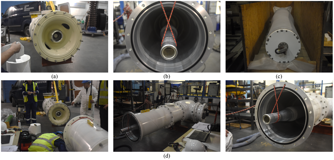
Figure 3 - GIB demonstrator setup: (a) insulating spacer, (b) straight conductor section, (c) HV bushing and (d) illustration of demonstrator assembly process
For the withstand voltage tests, the voltage waveforms and their tolerances are defined in accordance with IEC 60060-1:2010, and listed as follows [15]:
- Standard AC (50 Hz) voltage waveform within ±1% of test voltage;
- Switching Impulse (SI) [250 (±20%) / 2500 (±60%) μs] within ±3% of test voltage;
- Lightning Impulse (LI) [1.2 (±30%) / 50 (±20%) μs] within ±3% of test voltage.
Figure 4 shows the fully assembled GIB demonstrator separated into two zones: the bushing zone and the test zone. Both zones have an operating pressure of 4.5 bar. The bushing zone was always filled with SF6. As for the test zone, it was initially filled with SF6 for a benchmark test to ensure that the setup was correctly assembled before testing with an alternative candidate.
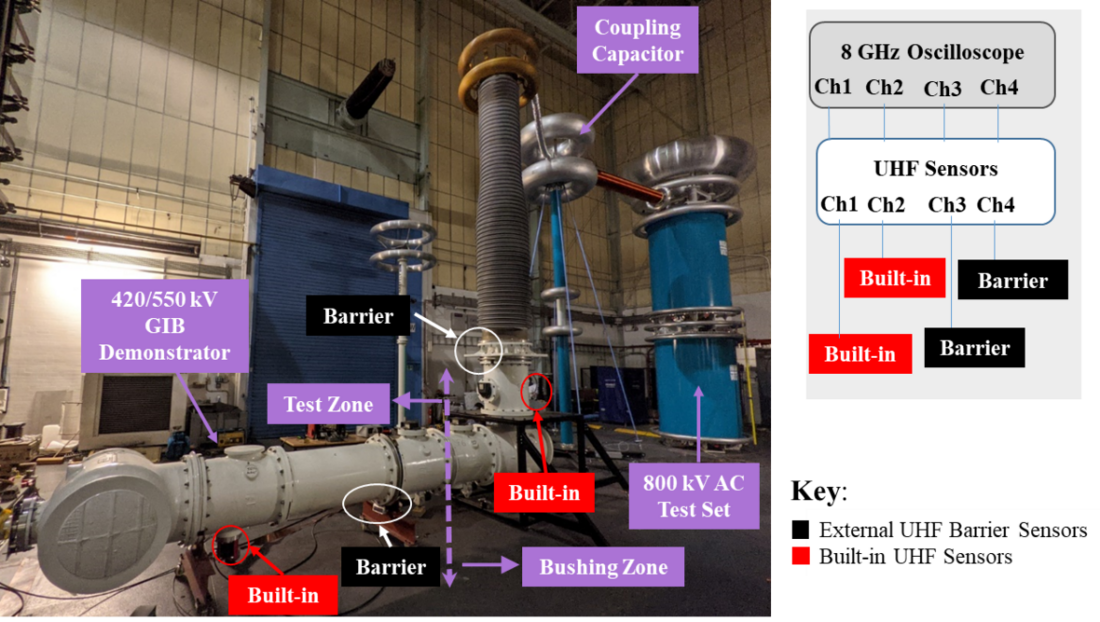
Figure 4 - Photo of the full-scale demonstrator with the location of PD sensors illustrated
Two corona rings were installed to minimize corona activities at the top of the bushing. Two built-in ultra-high frequency (UHF) PD couplers with a bandwidth of 200-1500 MHz were installed for PD measurement. Two additional UHF sensors with a bandwidth of 300-2000 MHz were positioned over viewing slots of the earth continuity bond on top of the conical insulator [6]. The expected frequencies of discharges for PD activity in insulating gases are in the GHz range. A Lecroy ultra-wide band oscilloscope with a bandwidth of 8 GHz was used to measure these signals. Prior to testing, a sensitivity verification procedure was performed using one UHF sensor as a transmitter and the remaining sensors as receivers.
3.2. IEC Type Test Procedure
The full-scale GIB demonstrator is dimensionally designed to withstand up to 550 kV basic insulation level (BIL) but is used by NGET for the 400 kV transmission network in the UK. As the equipment is rated for 420 and 550 kV BIL, both voltage levels were type tested using a 20% C3F7CN / 80% CO2 mixture. Withstand type tests were conducted as per IEC 62271-204:2011 [14]. Type tests of LI, SI, PD and AC were carried out and the test procedures for all voltage waveforms are summarized in Table 2 [6].
| Test | Description | Test Conditions and Pass Criteria |
|---|---|---|
| AC withstand voltage test | Maintain Ud for 1 minute | Ud = 650 kV (Ur = 420 kV) |
AC + partial discharge (PD) test | Upre-stress = Ud for 1 minute | UPD-test = 291 kV (Ur = 420 kV) |
Lightning impulse (LI) voltage test | 15 impulses of both polarities | ±1425 kV LI (Ur = 420 kV) |
Switching impulse (SI) voltage test | 15 impulses of both polarities | ±1050 kV SI (Ur = 420 kV) |
3.3. Gas Handling Process
Preparation: Any pressure compartment must always be vacuumed and filled with a dry gas, such as CO2, slightly above the atmospheric pressure and left for a few hours to absorb any residual moisture. The compartment is again vacuumed below 1 mbar before filling to the desired operating pressure with the test gas or mixture.
Filling: For the initial filling procedure of gas mixtures, the Manometric method based on Dalton’s law of partial pressures was adopted. This states that the total pressure of a mixture of non-reacting gases is equal to the sum of the partial pressures of individual gases [16]. This can be expressed mathematically as follows:
(1)
where P1…, Pn represent the partial pressures of individual gases and Ptotal is the total pressure of the gas mixture.
C3F7CN was first filled to the required partial pressure and then topped up with CO2 to reach the desired total pressure of the gas mixture. The filling of CO2 must be performed slowly toavoid a possible “forced cooling” effect that results in the liquefaction of some C3F7CN due to the cooling effect caused by rapid expansion of CO2 into the compartment.
Mixing: A re-circulation loop is used after the filling of a mixture. The entire volume of gas inside the pressure compartment is circulated for a minimum of two cycles, which is dependent on the compressor rating in m3/hour and the compartment volume. This is to ensure that the gas mixture is homogeneously mixed before initiating any test.
Analysis: For SF6, a purity of >97% is always used as per IEC 60480:2004 [17]. A bespoke alternative gas analysis instrument capable of measuring a 15-30% of C3F7CN with a deviation of ±1% was used to determine the gas mixture ratio. SF6 was recorded to have a 99.8% purity while the gas mixture had a ratio of 20.7% C3F7CN / 79.3% CO2 without any trace of O2.
Recovery and Re-use: Used gases must be recovered into their respective storage cylinders as part of a close-loop system. Depending on the level of decomposition, these aged gases could be re-used for additional tests. C3F7CN tends to liquefy when its partial pressure within a mixture exceeds ≈2.5 bar as result of its boiling point. Liquefaction can be prevented if the storage pressure is well below the saturation vapor pressure of the mixture taking into account the worst-case room temperature. In the event of liquefaction, a heating blanket is used to pre-heat the storage cylinder so that the gas mixture becomes homogeneous prior to filling.
4. Experimental Validation of Full-scale Demonstrator
4.1 IEC Type Test Results
Table 3 shows that 20% C3F7CN / 80% CO2 gas mixture passed the withstand type tests for 420 kV rating as successfully as SF6 [6]. There was no breakdown occurrence during the SI, LI and power frequency withstand tests at the specified voltage levels in IEC 62271-204:2011 [14]. For the UHF setup, PD discharges emit a signal of at least 16 mVpk-pk and any signal exceeding this value defined as a PD discharge inside the equipment. The equipment was pre-stressed at 650 kV ACRMS for 1 minute and subsequently energized at 291 kV ACRMS voltage for more than 30 minutes. A maximum noise level of 8.01 mVpk-pk was recorded from the UHF sensors during this period, which indicates no PD activity in the GIB and passed the test. Upon completion of the 420 kV type tests, the retro-filled demonstrator was increased to voltage levels specified for the 550 kV BIL. Similar to 420 kV BIL, Table 3 shows that no breakdown occurrence was recorded even at an elevated voltage level for all voltage waveforms. For the PD test, a maximum signal of 11.42 mVpk-pk was recorded at 381 kV ACRMS voltage after 30 minutes energization tested with a 20% C3F7CN / 80% CO2 gas mixture. This demonstrates that both gas media possess comparable dielectric performance tested in a full-scale industrial equipment. These tests have effectively established that a 20% C3F7CN / 80% CO2 gas mixture could be retro-filled with a significant safety margin for the 400 kV GB transmission network.
| Rated Voltage | Test | 20% C3F7CN / 80% CO2 | 100% SF6 |
|---|---|---|---|
420 kV | ±1050 kV SI | 0/15 | 0/15 |
±1425 kV LI | 0/15 | 0/15 | |
650 kV AC | No breakdown | No breakdown | |
291 kV PD | Signals | Signals | |
550kV | ±1175 kV SI | 0/15 | 0/15 |
±1550 kV LI | 0/15 | - | |
710 kV AC | No breakdown | No breakdown | |
381 kV PD | Signals | Signals |
4.2. Non-standard Type Test Results
Additional non-standard type tests were carried out using impulse waveforms to push the limit of the chosen gas mixture retro-filled in the demonstrator. The non-standard type tests were carried out at 420 kV BIL and listed as follows:
- Increasing Impulse Applications: An increased number of impulse applications from 15, per IEC standards, to 30, which is to investigate the behavior of 20% C3F7CN / 80% CO2 gas mixture under an increased number of overvoltage transient events.
- Under-pressure: The operating pressure was reduced to 4 bar to simulate a severe gas leakage event. Type tests at this reduced pressure will determine whether the gas mixture is still able to withstand the required LI and SI voltage levels.
Table 4 shows that the use of a 20% C3F7CN / 80% CO2 gas mixture has successfully passed the LI and SI tests of both polarities with no breakdown occurrence, despite doubling the number of impulse applications for the specified 420 kV BIL. Furthermore, the operating pressure was reduced from 4.5 bar down to 4 bar, representing a pressure drop of >10%. However, the LI and SI type tests of both polarities had no breakdown occurrence recorded at 420 kV BIL. Note that the liquefaction temperature of a 20% C3F7CN / 80% CO2 gas mixture at 4 bar is around -13 °C, which is an extra 3 °C temperature margin for the retro-filled equipment. Standard and non-standard type tests have shown the dielectric performance of a 20% C3F7CN / 80% CO2 gas mixture is comparable to SF6 as a potential replacement solution without having to change the equipment. Note that the differences in the thermal performance of the new gas candidate under high load have not been covered in this study. Similar experimental validation approach could be adopted for other equipment of different make, dimension or voltage rating to examine whether the use of SF6 in passive components could eventually be phased out.
| Rated Voltage | Test | 20% C3F7CN / 80% CO2 |
|---|---|---|
| (i) Increased Number of Impulse Applications | |
420 kV | ±1050 kV SI | 0/30 |
±1425 kV LI | 0/30 | |
| (ii) Reduced Operating Pressure to 4 bar | |
420 kV | ±1050 kV SI | 0/15 |
±1425 kV LI | 0/15 | |
5. Potential Retro-fill Locations in the UK
Outdoor equipment retro-filled with a 20% C3F7CN / 80% CO2 mixture can be operated down to -10°C at 4.5 bar. Therefore, it is important to assess the probability of reaching this temperature in potential retro-fill sites in the UK. Table 5 reports NGET substations rated at transmission voltages that possess the largest amounts of installed SF6 (>20 t). These substations represent approximately 40% of NGET’s total SF6 inventory. Historic temperature data have been obtained from weather stations close to the locations of substations outlined in Table 5. The weather stations shown in Table 6 have been capturing temperature data that is publicly available on the Met Office website [18]. The majority of the reported substations are located in the South East region of the UK. Five weather stations have been chosen to cover the temperature profiles of regions close to the substations shown in Table 5. The mean daily minimum temperature recorded from 1990 to 2018 shows that the Durham weather station had the lowest mean daily minimum temperature of -3.4 °C recorded in December 2010 [18].
| Map Location | Substation Name and Voltage Rating | SF6 Inventory (t) | |
|---|---|---|---|
1 | BRAMFORD, 400 kV | 53 | |
2 | ST JOHNS WOOD, 400 kV | 37 | |
3 | CONNAHS QUAY, 400 kV | 31 | |
4 | WEST HAM, 400 kV | 28 | |
5 | HACKNEY, 400 kV | 27 | |
6 | SELLINDGE, 400 kV | 26 | |
7 | NORTON, 400 kV | 26 | |
8 | LITTLEBROOK, 400 kV | 25 | |
9 | KILLINGHOLME, 400 kV | 24 | |
10 | BARKING, 400 kV | 22 | |
11 | SIZEWELL, 400 kV | 22 | |
12 | GRAIN, 400 kV | 22 | |
13 | NEW CROSS, 275 kV | 21 | |
| Map Location | Weather Station Location | Mean Daily Minimum Temperature |
|---|---|---|
A | Durham | -3.4 °C |
B | Sheffield | -1.9 °C |
C | Lowestoft | -1.4 °C |
D | Heathrow | -1.5 °C |
E | Manston | -1.0 °C |
Temperatures tend to be slightly lower in the North of England than the South East region. The data presented are the mean daily minimum temperatures which means that it is possible to have short periods in a day where the outdoor temperature drops close to the liquefaction temperature of -10 °C for a 20% C3F7CN / 80% CO2 mixture. This could potentially be considered as acceptable for normal operation since the internal conductor carries several thousands of amps during high-load conditions and this will inherently heat up the gas medium. Appropriate temperature control measures are required for scenarios where the current flowing through the conductor is close to the minimum temperature due to light or no-load conditions during a cold winter period.
6. Conclusions
This paper presents an investigation into the technical feasibility of adopting a 20% C3F7CN / 80% CO2 gas mixture as a potential retro-fill replacement of existing passive components designed for SF6 . The main conclusions are as follows:
- A comparative analysis was performed on existing literature for coaxial configurations that mimic the field uniformity as found in GIL/GIB equipment. Breakdown results of different alternatives in such prototype demonstrated that a 20% C3F7CN / 80% CO2 gas mixture possesses comparable dielectric performance to SF6 necessary for a retro-fill solution.
- Type tests with a GIB demonstrator showed that the chosen gas mixture has successfully passed all the required IEC type tests specified for 420/550 kV BIL. Additional non-standard type tests in 420 kV BIL also had no breakdown occurrence even when the operating pressure was reduced to 4 bar. This establishes a greater level of confidence that a retro-fill solution is viable in SF6-designed equipment.
A liquefaction temperature of -10 °C for the chosen gas mixture is a potential limitation for outdoor equipment. However, a review of the minimum temperature profiles from the main SF6 substations in the UK identified that it is very rare that the mean daily minimum temperature can go below -10 °C.
References
- IPCC, “Climate Change 2013: The Physical Science Basis. Working Group I Contribution to the Fifth Assessment Report on Interngovernmental Panel on Climate Change,” 2013.
- Y. Kieffel, T. Irwin, P. Ponchon, and J. Owens, “Green Gas to Replace SF6 in Electrical Grids,” IEEE Power and Energy Magazine, vol. 14, no. 2, pp. 32–39, 2016.
- BEIS, The United Kingdom National Statistics Authority, Jul 2018.
- E. Laruelle et al., “Reduction of greenhouse gases in GIS pilot project in UK,” CIGRE Session 46, C3-304, 2016.
- Y. Kieffel et al., “SF6 Alternative Development for High Voltage Switchgears,” CIGRE Session 45, D1-305, Paris, France, 2014.
- L. Loizou et al., “Technical Viability of Retro-filling C3F7CN/CO2 Gas Mixtures in SF6-designed Gas Insulated Lines and Busbars at Transmission Voltages,” IEEE Transactions on Power Delivery, vol. 35, no. 5, pp. 2394-2402, Oct. 2020.
- L. Chen et al., “Potential of CF3I/CO2 Gas Mixture in Gas-Insulated Equipment,” IEEE Conference on Electrical Insulation and Dielectric Phenomena, Ann Arbor, USA, 2015.
- L. Chen et al., “CF3I Gas Mixtures: Breakdown Characteristics and Potential for Electrical Insulation,” IEEE Transactions on Power Delivery, vol. 32, no. 2, pp. 1089-1097, Apr. 2017.
- P. Ranjan et al., “Anomalous First Breakdown Behavior of HFO1234ze(E),” IEEE Transactions on Dielectrics and Electrical Insulation, vol. 28, no. 5, pp. 1620-1627, Nov. 2021.
- P. C. Stoller et al., “Mixtures of CO2 and C5F10O perfluoroketone for high voltage applications,” IEEE Transactions on Dielectrics and Electrical Insulation, vol. 24, no. 5, pp. 2712-2721, Oct. 2017.
- L. Loizou, L. Chen, Q. Liu, and M. Waldron, “Lightning Impulse Breakdown Characteristics of SF6 and 20% C3F7CN / 80% CO2 Mixture under Weakly Non-Uniform Electric Fields,” IEEE Transactions on Dielectrics and Electrical Insulation, vol. 27, no. 3, pp. 794-801, Jun. 2020.
- Subcommittee on Iodotrifluoromethane, Iodotrifluoromethane: Toxicity Review, Washington, USA: The National Academies Press, 2004.
- L. Chen, M. S. Kamarudin, H. Griffiths, and A. Haddad, “Breakdown of CF3I Gas and its Mixtures under Lightning Impulse in Coaxial-GIL Geometry,” IEEE Transactions on Dielectrics and Electrical Insulation, vol. 23, no. 4, pp. 1959-1967, Aug. 2016.
- “BS EN 62271-204:2011: High-voltage switchgear, Part 204: Rigid gas-insulated transmission lines for rated voltage above 52 kV,” Br. Stand. Institutions, 2011.
- “BS EN 60060-1:2010: High-voltage test techniques, Part 1: General Definitions and test requirements,” Br. Stand. Institutions.
- M. S. Silberberg, Chemistry: The Molecular Nature of Matter and Change, 5th ed. Boston: McGraw-Hill, 2009.
- “BS EN 60480:2004 - Guidelines for the checking and treatment of sulphur hexafluoride (SF6) taken from electrical equipment and specification for its re-use,” Br. Stand. Institutions, 2004.
- UK Government. Met Office [Online]. Available: https://www.metoffice.gov.uk/