B4 - Transmission system testing of a VSC based HVDC System
Authors
M. MEISINGSET, S. BØDAL - Stattnet, Norway
K. KOREMAN - TenneT, Netherlands
A. VINOTH - Hitachi Energy, Sweden

Summary
NordLink is an HVDC interconnector between the 420 kV substation at Ertsmyra in Norway and the 380 kV substation at Wilster in Germany. The interconnector is designed as a bipole without dedicated metallic return cable, with two largely independent pole converters at each converter station, for increased availability and reliability performance. NordLink is rated for ±515 kV d.c. system voltage and 1400 MW transmission capacity. Cascaded Two-Level (CTL) Voltage Source Converter (VSC) technology has been used to achieve low losses, minimize a.c. filtering, fast-acting voltage control capability and enable import during low short circuit conditions in Norway.
The HVDC converter stations in Norway and Germany were commissioned for STATCOM-operation in the summer of 2019 [1] and the spring of 2020.
NordLink was successfully commissioned with power transmission in the autumn of 2020. The paper describes the system testing of two functionalities during commissioning, which is important to obtain the required reliability and availability performance of NordLink. The first functionality is the fast transition from bipole to monopole operation when a fault occurs in one converter pole either in Norway or Germany. The second functionality is the auto-reclosure for temporary faults in the HVDC overhead line between the transition station and the converter station in Norway.
NordLink performed successfully a 90-day trial operation period from December 2020 to March 2021.
Keywords
VSC – HVDC – Bipole – Commissioning1. Introduction
NordLink is an HVDC interconnector between Norway and Germany, which was commissioned in the fall of 2020. The interconnector is rated for ±515 kV d.c. system voltage and 1400 MW transmission capacity in the receiving end. The HVDC interconnector consists of two VSC converter stations, 53 km overhead line in Norway [2], 515 km of submarine cable and 55 km of underground cable in Germany. In addition, there is a transition station at the Norwegian coast, where the overhead line is connected to the submarine cable. Figure 1 shows the location of the converter stations and the cable route. To fully utilize the advantages of VSC technology, the converters are designed with reactive power capacity for steady-state conditions and fast voltage support during transient conditions, such as during faults in the connected a.c. transmission grid.
The HVDC interconnector is designed as a bipole without dedicated metallic return cable, with two largely independent pole converters at each converter station, for increased availability and reliability performance. The main operating mode is bipole operation, but each pole can run in monopole operation to allow preventive maintenance and corrective repair work of the other disconnected pole. In this case, the pole conductor of the disconnected converter is reconfigured for use as a metallic return. The converter stations are equipped with a d.c. bypass arrangement with high-speed switches. If a pole should trip due to a converter fault, this arrangement will enable the transition from bipole to monopole operation in approximately one second. There is one special operation mode available that allows one pole to operate in power transmission mode and the other pole on each side of the HVDC Interconnector to operate in STATCOM mode. The configuration of the HVDC interconnector is shown in Figure 2.
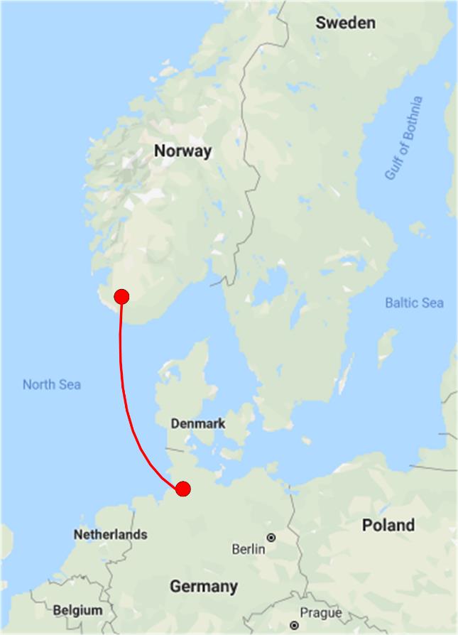
Figure 1 - NordLink HVDC Interconnector
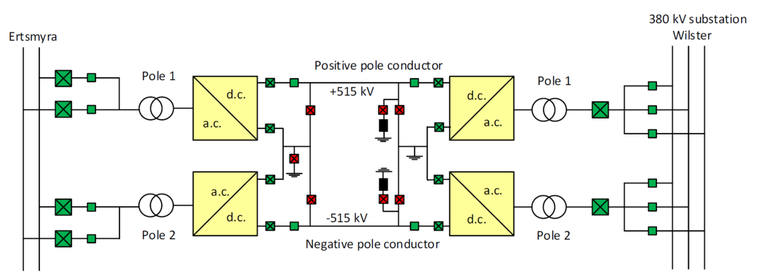
Figure 2 - Simplified single line diagram of NordLink HVDC interconnector
1. The converter stations
The Norwegian converter station is located at Ertsmyra, close to Tonstad in Sirdal municipality. In parallel with the construction of the HVDC Interconnector, the a.c. transmission grid in southwest Norway has been upgraded from 300 to 420 kV to provide sufficient transmission capacity for the next decades. Part of this voltage upgrade is a new 420 kV a.c. substation at Ertsmyra, that is the point of common coupling for NordLink. Tonstad hydro-power plant with an installed capacity of 960 MW is located just a few kilometres from Ertsmyra substation. With a yearly estimated generating capacity of 4000 GWh, this is the largest generating power plant in Norway. The close proximity to fast-acting hydropower generation makes NordLink well suited to compensate for variation in unregulated solar- and wind generation in continental Europe.
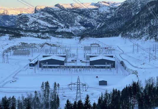
Figure 3 - HVDC converter station at Ertsmyra, Norway
Figure 3 shows Ertsmyra substation with the NordLink HVDC converter station in the front and the 420 kV a.c. substation in the background.
The HVDC converter station in Norway is connected to the 420kV a.c. substation at Ertsmyra by two overhead line (OHL) connections and two double circuit breaker bays with conventional Air Insulated Switchgear (AIS), as shown in Figure 2. This enables one converter pole to operate in power transmission mode, and the other pole to operate in STATCOM mode. Dedicated switches are installed to enable the connection of each pole converter to ground to obtain this functionality. A simplified single line diagram of Ertsmyra converter station is shown in Figure 4. The converter station has an outdoor DC yard.
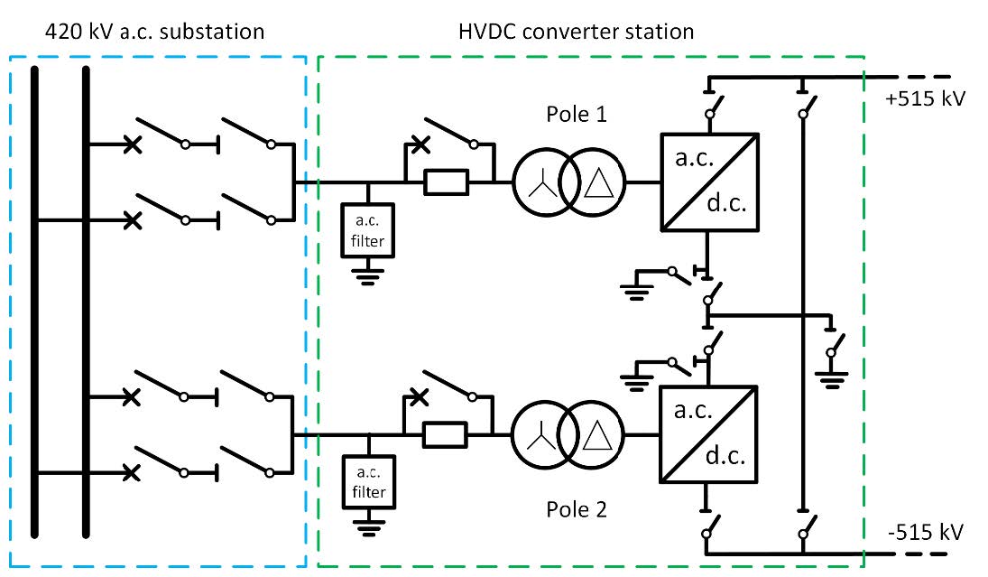
Figure 4 - Simplified single line diagram of Ertsmyra converter station
The 420 kV a.c. substation at Ertsmyra has a double busbar arrangement equipped with a manual operated busbar sectionalizer. One northbound 420kV OHL, one 420kV southbound OHL and one HVDC converter pole are connected to each side of the sectionalizer. This enables the substation to maintain the operation of one north-southbound 420kV OHL and one converter pole in case of a busbar fault when one busbar section is disconnected for planned maintenance.
The HVDC converter station in Germany is connected to the 380 kV a.c. substation at Wilster by two underground cable connections and two single circuit breaker triple busbar bays with conventional Air Insulated Switchgear (AIS).
HVDC converter station at Wilster is shown in Figure 5. There are two main buildings in green, one for each 700 MW converter pole. Each building consists of three parts, containing the phase reactors, the valves and the DC yard.
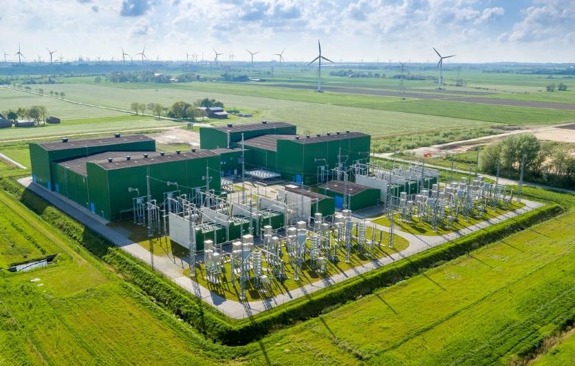
Figure 5 - HVDC converter station at Wilster, Germany
Source: http://www.tennet.eu
2. Commissioning overview
The NordLink HVDC converter station in Norway was successfully commissioned for STATCOM operation mode in July 2019 [1]. The STATCOM performance requirements with respect to various operating modes and functionality were verified. As the power transmission tests for the HVDC interconnector were not planned to commence before autumn 2020, the commissioning team took advantage of the unique opportunity to extensively test the STATCOM performance of the two converter poles in Norway during the summer of 2019. The commissioning and testing were performed according to the recommendations in Cigré technical brochure 697 [3]. Commissioning of the HVDC converter station in Germany for STATCOM operation was performed in the spring of 2020.
The installation of the last HVDC cable section, the two 55 km underground cables in Germany, was completed in the summer of 2020. The commissioning of the HVDC Interconnector with power transmission testing started on September 2nd 2020. The cable discharge resistors at Wilster were damaged through arcings after several cable discharges during testing in the early stages of the commissioning period. Some design modifications were implemented in the cable discharge resistors to improve the internal voltage distribution. This included replacement of ceramic bushings by silica glass insulators and addition of grading capacitors units. The purpose of the cable discharge resistors is to de-energize the cables which are connected to the faulty converter pole and prepare the cables for metallic return operation during monopole operation of the HVDC Interconnector. The cable discharge resistors were dismantled and the commissioning program continued without performing the tests involving the use of the cable discharge resistors.
NordLink started commercial operation on December 18th 2020 at the commencement of the 90-day trial operation period. The trial operation period was performed without the cable discharge resistors available and was successfully completed on March 18th 2021. The new re-designed cable discharge resistors were installed and the remaining part of the commissioning program, including rapid cable discharge, was performed during March 24-26th 2021. The converter stations were taken over by NordLink Norge AS (Statnett 100%) and DC Nordseekabel GmbH & Co. KG (TenneT 50% and KfW 50%) on March 31st 2021. Asset management at Statnett and TenneT were given the operational responsibility on April 1st 2021.
2.1. Fast transition from bipole to monopole operation
NordLink is designed as a rigid bipole system with two pole conductors without dedicated metallic or sea return. If one converter pole is out of operation due to maintenance or repair, the other converter pole can operate in monopole mode using the conductor belonging to the disconnected converter pole as a metallic return. To enable fast transition between bipole and monopole operation mode, the converter stations are equipped with a d.c. bypass arrangement with High-Speed Switches (HSS). These switches are modified a.c. circuit breakers, thus allowing for fast operation as compared to the conventional disconnectors. This enables fast transition between different configurations. These modifications mean that the a.c. breakers are re-designed for the higher 515 kV d.c. operating voltage using longer insulation distances and corona rings. The breaking chamber and the operating mechanism are not modified.
The fast transition from bipole to monopole operation is an automatic switching sequence which is initiated by a trip signal in one converter pole. Hence, the occurrence of a fault causing trip in one converter pole, initiates a transition from balanced bipolar operation to monopolar metallic return operation to maintain continued power transmission within the available capacity of one pole (i.e. 685 MW). The sequence includes ramping down the pre-fault bipole power flow to zero, reconfiguration in the bypass arrangement of the HVDC Interconnector and power ramping back to the pre-fault power flow level limited by the capacity in one pole. The faulty converter pole will trip by opening the a.c. circuit breakers, and it will also be isolated from the d.c. side. On the other end of the HVDC Interconnector, the healthy converter of the disconnected pole will also be isolated on the d.c. side, but it remains connected to the a.c. side and transfers into STATCOM operation mode. Hence, a fault in the positive converter pole in Norway results in monopole operation with the positive pole conductor as a metallic return and STATCOM operation in the disconnected converter pole in Germany, as shown in Figure 6. The d.c. switches shown in green colour are closed whereas the switches in red colour are open for this configuration. The cable discharge resistors at Wilster are indicated in black colour.
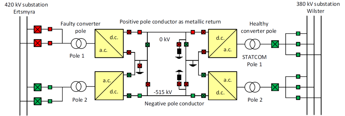
Figure 6 - Simplified single line diagram of NordLink HVDC interconnector in monopole operation
The time from fault detection to the reconfiguration of the bypass arrangement has been completed, is approximately 1 second. The subsequent power ramping to the rated monopole power transmission takes 2 seconds regardless of the pre-fault power transmission level. A fixed ramping time with sufficient duration was chosen to avoid undesirable impact in the power system, which potentially could be caused by a fast ramping of the power transmission within a few ms. Hence, the total transition time from pre-fault bipole operation to monopole operation is expected to be approximately 3 seconds.
The purpose of this functionality is to lower the risk of a bipole trip and avoid instantaneous surplus or deficit of 1400 MW in the synchronous Nordic transmission system. In the occurrence of a fault in one converter pole in Norway or Germany, monopole operation limited to the rated power transmission capacity (i.e. 685 MW) in one converter pole can be maintained, as well as STATCOM operation in the healthy converter of the disconnected pole at the opposite end of the HVDC Interconnector.
As the transition sequence involves several connections and disconnections of many switches in the d.c. bypass arrangement, with conditions and permits for every step in the sequence, the transition was first tested with low power transmission in the HVDC Interconnector during commissioning. When this test verified that the transition sequence was working correctly, the transition sequence was tested with high power transmission. The fast transition from bipole to monopole operation was initiated by switching off both pumps for the valve cooling system in the positive converter pole 1 at Ertsmyra.
The HVDC cable discharge resistors were re-designed and installed after the successful completion of the 90-day trial operation period. Figure 7 shows the transient performance of the HVDC Interconnector during the testing of the fast transition from bipole to monopole operation. The transition sequence was initiated by a valve cooling pump failure in converter pole 1 at Ertsmyra. The commissioning test of this functionality was performed on March 25th 2021.
The pre-fault power transmission in bipole operating mode was 720 MW from Norway to Germany. The test initiated a trip of converter pole 1 and fast transition to monopole operation with the positive pole 1 conductor as a metallic return. The 720 MW pre-fault power transfer was chosen to verify that the post-fault power transmission was ramped to 685 MW, which is the maximum power transfer capacity in monopole operation.
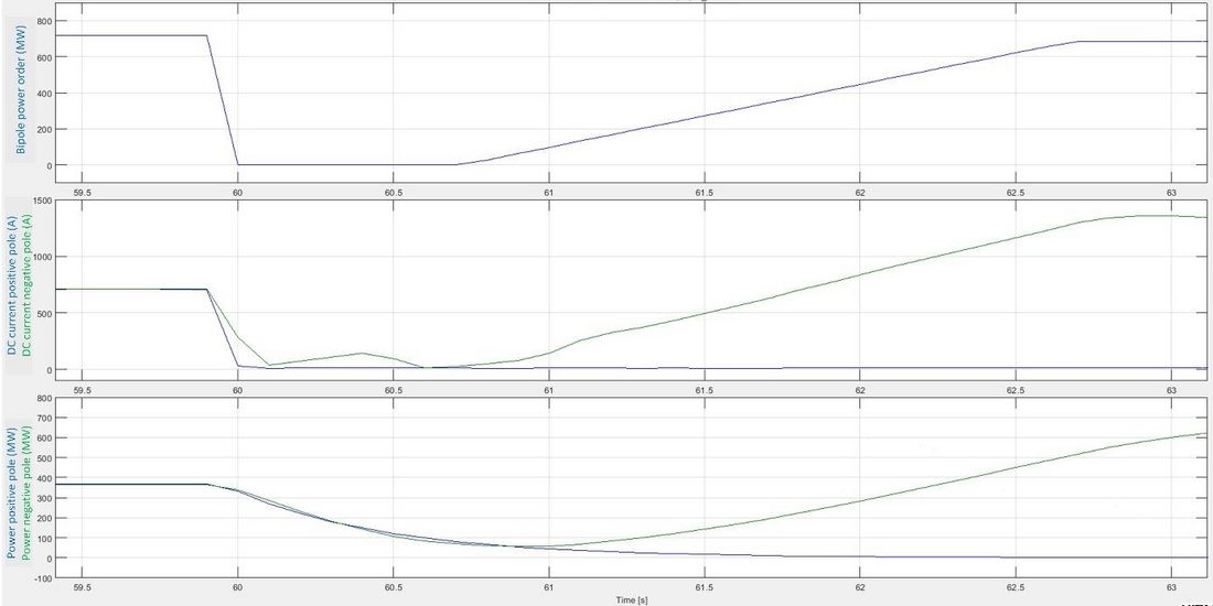
Figure 7 - Fast transition from bipole to monopole operation with pole 1 conductor as a metallic return
Figure 7 shows the fast transition from balanced bipolar operation to monopolar operation with pole 1 conductor as metallic return initiated by a valve cooling pump failure in converter pole 1 at Ertsmyra. The sequence starts by ramping down the pre-fault 720 MW bipole power transfer to zero. The ramping down of both the bipole power order and the measured DC current in the faulty converter pole 1 at Ertsmyra takes approximately 100 ms. Then, the required switching of the d.c. bypass arrangement at both converter stations to disconnect the faulty converter pole is performed in 0.8 seconds. Hence, the time from fault detection to completion of the reconfiguration of the bypass arrangement is about 0.9 seconds. The last part of the transition sequence restores the power transmission to rated 685 MW monopole power transmission. The power transmission was restored during 1.95 seconds ramping time. The ramping speed for the power order was set to 350 MW/s. The healthy converter pole 2 now carries sufficient DC current to transmit the entire post-fault power of 685 MW. The ramping time of the DC current in pole 2 follows the ramping time of the power order. Hence, ramping of the actual power transmission also follows the ramping of the power order. Unfortunately, the graph showing the actual power transmission in pole 1 and 2 are filtered curves, which gives the incorrect impression that the ramping of the actual power transmission is slower than the power order. The total transition time from fault detection in bipole operation to monopole operation with the restoration of the power transmission takes 2.85 seconds.
Both the faulty converter pole 1 and the healthy converter pole 2 at Wilster remain deblocked though the complete transfer sequence from bipole to monopole operation. The only difference is that pole 1 is disconnected from the d.c. side at Wilster and thus transfers into STATCOM-operation. Both converter poles at Wilster also remain in Q-control operating mode and maintain their Mvar output without interruption.
2.2. Clearance of d.c. overhead line faults with restart
The 53 km HVDC overhead transmission line from the converter station at Ertsmyra to the transition station at Vollesfjord is routed through harsh environmental conditions in the mountains. The overhead line is exposed to snow and ice build-up during winter, occasionally salt spray from the sea near the coast and lightning strikes in the summer. It is expected that these environmental conditions will occasionally cause pole-to-ground faults on the overhead HVDC transmission line. To reduce the consequences of losing 1400 MW in the transmission systems due to such temporary faults in the HVDC overhead line, the HVDC Interconnector is equipped with an automatic reclosure functionality.
Vollesfjord transition station is located at the coastline in Norway and interconnects the HVDC overhead line and the submarine cables. The transition station is equipped with a disconnector with earthing switches on each side, and an optical current measurement unit, for each pole conductor. These current measurements from the transition station at Vollesfjord, together with current measurements from the converter station at Ertsmyra, are input signals for the overhead line differential protection. This protection device is used for the detection of pole-to-ground faults on the overhead line, and subsequent activation of the automatic reclosure functionality.
Statnett has no previous experience with automatic reclosure functionality of any HVDC Interconnectors. A full-scale field test was therefore performed to verify this functionality. The test was performed by intentionally subjecting a pole-to-ground fault on the negative pole 2 on a temporary extension of the permanent busbar arrangement in the DC yard in the converter station at Ertsmyra. A similar field test of a pole-to-ground fault in a d.c. overhead line was performed in Canada in 2015 [4].
Figure 8 shows the test arrangement for the staged fault in the negative pole conductor of the overhead DC line, where the temporarily extended busbar indicated in red, just before the short circuit to ground fault was subjected.
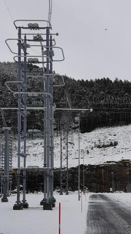
Figure 8 - Field test arrangement for an overhead DC line fault at Ertsmyra converter station
When the pole-to-ground fault was subjected, a flame arc was ignited at the fault location. Thus, an HVDC-overhead line fault was detected which activated the HVDC line differential protection and initiated the auto-reclosure sequence to restore the power transmission. The first part of the sequence was to clear the fault by de-energizing the faulty converter pole 2 of the HVDC Interconnector. This was done by blocking the HVDC converter valves and opening the 420/380 kV a.c. circuit breakers in the faulty converter pole at each end of the HVDC Interconnector. After the opening of the a.c. circuit breakers, the fault current contributions from the a.c. networks through the converter transformers stop and the flame arc extinguishes. Approximately 400 ms after the a.c. circuit breakers were opened, a re-energization of the HVDC Interconnector was attempted by closing the a.c. circuit breakers and de-blocking the valves in the faulty converter pole. The re-energizing is successful if the dielectric withstand level in the fault location in the DC overhead line, has been restored to normal pre-fault value. The ramping to pre-fault power transmission level is then performed in the HVDC Interconnector.
The HVDC Interconnector shall be capable of restoring the active power transmission and reactive power exchange for both converter stations to a minimum of 90% of the pre-fault values within 1 second after the clearance of a fault on the overhead DC line section of the HVDC Interconnector. The auto-reclosure function after detection of a fault in the d.c. overhead line is designed for one automatic restart attempt. This means that the pre-insertion resistors are designed for the heat absorption required for one restart attempt only. If the restart attempt fails, it means that the d.c. fault is not cleared and the HVDC Interconnector will be tripped. The converters may then be restarted manually in STATCOM operation mode, disconnected from the d.c. side.
Two full-scale short-circuit field tests were conducted as part of the system tests with 50 MW HVDC power transmission from Norway to Germany.
The first short-circuit test, performed on November 27th 2020, was unsuccessful as it caused the HVDC Interconnector unintentionally to trip due to an activation of the pole current differential protection in the faulty converter pole. This interrupted the auto-reclosure sequence and no restart attempt was made. To avoid this, the settings of this protection device were adjusted.
The second short-circuit test shown in Figure 9, was conducted on December 4th 2020, verified that the auto-reclosure function performed properly. It was however revealed that the setting of the reclose time from the opening to the closing of the a.c. circuit breakers in the auto-reclosure sequence was too long (730 ms). This caused the DC voltage across the IGBT valve gate units to decrease below the threshold value, which delayed deblocking of the valves in the restarting converter pole by 2.14 seconds. The valve gate units will lose the energized indication 685 ms after the converter a.c. circuit breaker opened, meaning that all the switching must be completed within 590 ms.
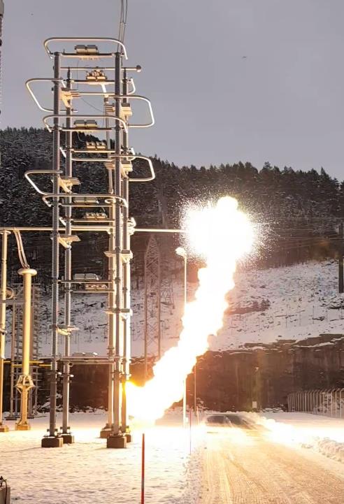
Figure 9 - Field test of a fault on the overhead DC line section of the HVDC Interconnector
This will enable converter Ready For Operation (RFO) to be achieved immediately after the energization. RFO means that the converter is energized and that all conditions are fulfilled to permit deblocking of the converter without any protective actions. In this case, the circuit breaker reclosure time was longer than 590 ms, which resulted in a significant delay in the RFO and deblocking of the valves. When the DC voltage across the valve gate units was restored to above the threshold level, the valves deblocked and the power transmission was restored to the 50 MW pre-fault value by ramping the DC current.
Figure 10 shows the transient performance of the HVDC Interconnector during the second full-scale pole-to-ground fault in the negative pole 2 conductor in the overhead d.c. line section of the HVDC Interconnector. The figure shows the bipole power order, the two pole conductor d.c. voltages at Ertsmyra, the two pole conductor d.c. currents at Ertsmyra and the three 420kV a.c. phase currents through the converter transformers in the faulty converter pole 2 at Ertsmyra.
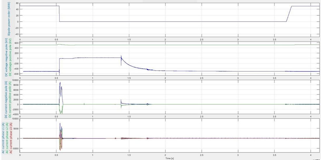
Figure 10 - A field test of a pole-to-ground fault on the overhead DC line section of the HVDC Interconnector to verify the auto-reclosure functionality
When the pole-to-ground fault occurs in the negative pole 2 conductor of the overhead d.c. line, the valves in the faulty converter pole 2 are blocked in both stations. The neutral bus at the d.c. side at Ertsmyra is grounded via the Neutral Bus Ground Switch (NBGS). The NBGS remains closed until the valves have deblocked. As a result, the d.c. voltage in the faulty negative pole 2 conductor drops rapidly to zero. The DC voltage in the healthy pole conductor remains close to the pre-fault value during the fault sequence. A fault current flows through the converter a.c. circuit breakers and in the d.c. pole conductor towards the location of the fault in the d.c. overhead line for a duration of 52 ms. The peak value of the DC fault current in the faulty pole conductor is about 9 kA. The DC current in the healthy pole conductor has a peak value of about 4 kA. The overhead line current differential protection in the faulty converter pole is activated, which detects the fault and initiates the restart sequence. At detection of the fault, the bipole power order is stepped down to zero.
The fault is cleared when the a.c. circuit breakers in the faulty converter pole 2 trip at both converter stations and thus interrupting the fault current contributions from the a.c. grids through the converter transformers. The Neutral Bus Switch (NBS) in the faulty pole opens at both stations to interrupt any circulating d.c. currents. The HSS in the faulty pole thereafter opens at both stations, which disconnects the faulty converter pole from the d.c. side. The pre-insertion resistor bypass switch opens to prepare for energization and restart. The NBS in the faulty pole is then re-closed at both converter stations. The restarting converter pole is now ready for energization.
The a.c. circuit breakers in the restarting pole remained open for 730 ms when they close at about t=1.3 s and re-energize the converter through the pre-insertion resistors. The pole HSS in the restarting converter pole closed at both stations at about t=1.4 s, which initiated the recharging of the d.c. voltage in the faulty pole conductor. The pre-insertion resistor bypass switch closes 430 ms after the closing of the a.c. circuit breakers at about t=1.73 when the d.c. conductor in the restarting pole has been sufficiently re-charged.
After energization, the RFO signal is required to permit valve deblock. In this situation, the IGBT valve gate units lost energized status prior to energization. As a result, there was no RFO achieved immediately after energization. Additional time was therefor required to re-charge the IGBT valve gate units to achieve RFO and permit the valves in the restarting converter pole to deblock. The RFO was achieved 2.14 seconds after closing of the a.c. circuit breakers. Hence, the 730 ms setting of the a.c. circuit breaker restart time caused a significant delay in deblocking of the valves. The time from valve block to deblock in pole 2 was 3.1 seconds. The NBGS at Ertsmyra opened 48 ms after RFO and the power ramping started 65 ms after RFO. The results show that the duration from fault clearance to the restoration of the pre-fault power transmission was approximately 3.2 seconds.
To avoid the decrease in the d.c. voltage across the valve gate units below the threshold value for valve deblocking, which was observed during the second field test, the time delay between the opening and closing of the converter a.c. circuit breakers was reduced from 730 to 400 ms. The circuit breakers are designed for 300 ms reclose time. It was necessary to modify settings in the control and protection system to achieve fast connection of the circuit breakers. These modifications included bypass of the synchronized switching device for the circuit breakers to avoid delay during auto-reclosure. A third test was therefore conducted to verify that the auto-reclosure function was performed within the required response time. The auto-reclosure sequence was initiated by making an online software activation of the overhead DC line current differential protection in the control and protection system. Hence, a simulation of a line-to-ground fault in the DC line was created to activate the current differential protection. Figure 11 shows the bipole power order in the HVDC Interconnector during the test.
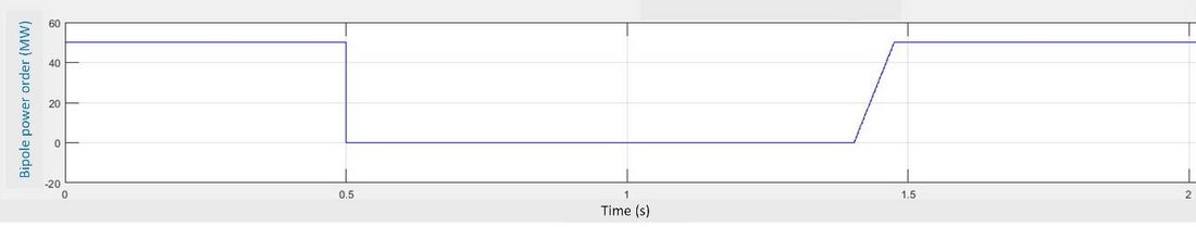
Figure 11 - Test of the response time of the overhead DC line auto-reclosure function (software test)
The HVDC Interconnector shall be capable of restoring the active power transmission to minimum 90% of the pre-fault value within 1 second after the clearance of a fault on the overhead d.c. overhead line. This initial required recovery time was subject to adjustment during detailed engineering. The test verified compliance to this requirement as the power transmission was restored within 950 ms after fault clearance, but only for this low 50 MW power transmission level. Hence, the adjustment from 730 to 400 ms in the circuit breaker reclose time, resulted in restoration time of 950 ms, which is a significant improvement compared to the 3.2 second restoration time observed in second field test.
The duration of the ramping of the power transmission was short at 70 ms, since the pre-fault power transmission was relatively low at 50 MW from Norway to Germany during the test. The post-fault ramping speed of the power transmission was set to 700 MW/second due to requirements from the Transmission System Operator's national control centre. Hence, the ramping time from zero to rated 1400 MW power transmission is currently 2.0 seconds. This 700 MW/s setting of the ramping speed means that the restoration time for the auto-reclosure function would be marginally shorter than 3 seconds if the d.c. fault occurred with 1400 MW power transmission in the HVDC interconnector.
Conclusion
The NordLink HVDC converter stations in Norway and Germany were commissioned for STATCOM operation mode in the summer of 2019 [1] and in the spring of 2020.
NordLink was successfully commissioned for power transmission mode in the autumn of 2020. The paper describes the system testing of two functionalities during commissioning, which are important to obtain the required reliability and availability performance of NordLink.
The first functionality is a fast transition from bipole to monopole operation when a fault occurs in one converter pole either in Norway or Germany. The converter station in Germany is equipped with cable discharge resistors to de-energize the faulty converter pole conductor and prepare the conductor for metallic return operation during monopole operation of the HVDC Interconnector. The transition from bipole to monopole operation with restoration of the pre-fault power transmission limited by the monopole capacity, was performed in less than 3 seconds. Hence, the test verified that the functionality worked correctly and within the required time response.
The second functionality is the auto-reclosure for temporary faults in the HVDC overhead line between the transition station and the converter station in Norway. Two full-scale field tests and one software test were conducted to verify the auto-reclosure function when a temporary pole-to-ground fault occurs in the overhead line section of the HVDC Interconnector. The tests verified that the auto-reclosure function was working properly. The active power transmission was restored to the 50 MW pre-fault value within 1 second after the clearance of the fault in the d.c. overhead transmission line.
References
- S. Bødal, M. Meisingset, C. G. A. Koreman, A. Vinoth, H. S. Andersson, "Commissioning of VSC HVDC converters for STATCOM operation", Paper B4-109 CIGRE 2020 Session Paris, France.
- S. Bødal, J. J. Bremnes, S. Vogt, C. G. A. Koreman, E. Matias, H. S. Andersson, "Interaction between parallel HVDC and a.c. overhead lines", Paper B4-128 CIGRE 2016 Session Paris, France.
- CIGRE Working Group B4.63, Technical brochure 697, "Testing and commissioning of VSC HVDC Interconnectors".
- B. Korbutiak, M. Mielke, H. Said, M. Paradis, P. Kuffel and R. Gignac, "Fault Staging On a 500kV Monopole Link Utilizing An Unmanned Aerial Vehicle". Paper B4-114 CIGRE Winnipeg 2017 SC A3, B4 and D1 Colloquium.