C4 - Taking advantage of grid-forming BESS behaviour during major outages: contribution to improve the share of renewable energy in French isolated power systems
Authors
G. SANTOS PEREIRA, G. PRIME - EDF Lab Paris-Saclay, France
F. BENAVENT - EDF Centre d’Ingénierie Système Transport, France
J. WITKOWSKI - EDF Systèmes Énergétiques Insulaires, France

Summary
The share of Variable Renewable Energies (VREs) in the French isolated power systems – i.e. Overseas Departments and Territories – is significantly increasing compared to previous years. The French government has decided that electric generation of these isolated systems must be fully be derived from renewable energy resources, progressively suppressing all classic fuel-based generation.
It is already well known in the state of the art that the massive insertion of VREs leads to many challenges vis-à-vis system stability. To pave the way, this paper investigates different solutions to guarantee (and improve) the stability of isolated power systems. For this purpose, a real isolated power system is used as a case study, and the stability of the system after a major incident is analysed for different scenarios with synchronous condensers, grid-feeding and grid-forming BESS (Battery Energy Storage System). Focus is applied to solutions based on grid-forming control strategy.
To be considered as a valid scenario, the system should resist a major generation loss without disturbing the under-frequency load shedding protection scheme, displaying abnormal steady-state equilibrium point, or breaking – even transiently – the synchronism between its sources. Different variants without synchronous generators can be considered as a solution, even improving system dynamics when compared with the base scenario.
The main results illustrate the benefits of a system fully based on oversized grid-forming BESS, however, considering the current industrial scenario, this solution is also the least realistic between them. A very realistic variant with a combination of synchronous condensers and grid-forming BESS may guarantee the stability of the system, presenting good advantages compared with other scenarios. However, remaining challenges related to the robustness and effectiveness of current limitation strategies of grid-forming control are still under investigation.
As a grid operator, EDF SEI considers grid-forming control of the BESS as a very valuable solution to increase VRE rates while ensuring system stability under any circumstance. However, there are still challenges under investigation to specify the behaviour of this new class of assets to guarantee system stability, respecting the harmony between system elements.
Keywords
Isolated power systems - Battery Energy Storage System - Grid-feeding - Grid-forming - Synchronous Condensers - Power System Stability - Under-frequency Load Shedding1. Introduction
Like many other electrical grids worldwide, the French isolated power systems such as Overseas Departments and Territories have experienced these past years a significant increase in their share of Variable Renewable Energies with power electronics interface (VREs) such as wind and photovoltaic. For example, the maximum instantaneous share of VREs was measured at 50% of the consumption in the power system of Corsica and may approach 35% in other island power systems operated by EDF SEI [1]. Therefore, the stability of these grids, in particular the frequency stability, is becoming more challenging due to the reduced inertia provided by the remaining conventional generators.
To overcome these frequency stability issues, several solutions have already been implemented in French isolated power systems to stabilise them despite their lower inertia levels such as:
- ROCOF based load shedding [2], [3].
- Fast frequency control and ROCOF based active power response (boost mode) from Battery Energy Storage Systems (BESS) [4]–[7].
- RESCU-F: dynamic frequency support in the form of a fast reduction of the active power of loads induced by a controlled reduction of the grid voltage [8], [9].
At the same time, grid-forming BESS operated by Energy Management Systems (EMS) are making instantaneous “100% renewable” operation possible in microgrids with periods without any conventional generators connected to the grid.
Grid-forming BESS is a recent solution in the scientific literature that has been applied successfully to many microgrids projects worldwide [10], [11]. It may become one of the main solutions to ensure the stability of larger isolated power systems. This study aims to address some of the remaining challenges that need to be investigated before large-scale deployment. One of these challenges is the correct operation of the under-frequency load shedding (UFLS) protection scheme, while the frequency becomes defined mostly or completely by several grid-forming BESS.
In microgrid applications, it is current practice to oversize and to divide a BESS into several subsystems in such a way that there can be no shortage of frequency containment reserve. Furthermore, the number of customer feeders is generally quite low and therefore the load shedding scheme can, in some cases, be managed directly by the EMS, not requiring a frequency dip below a given threshold.
In larger meshed isolated systems, with voltage levels above 50 kV, and load peaks reaching several hundreds of MW, oversizing grid-forming BESS to cover the frequency containment reserve would introduce a significant financial deoptimisation. Therefore, UFLS remains imperative and its efficiency is still important to avoid blackouts during major outages.
The objective of this paper is to investigate the behaviour of grid-forming BESS regarding frequency stability, determining the most appropriate solution for a large isolated power system. Furthermore, the study identifies other remaining challenges related to the application of grid-forming BESS to ensure a stable power system operation with a high penetration rate of VREs. For this purpose, a grid topology inspired from an actual French island grid and the EDF SEI grid code requirements regarding frequency stability are used.
This paper is organised as follows. Section 2 summarises modelling specificities of the isolated power system and its energy sources. Section 3 introduces the case study and the different scenarios considered in the analysis. Detailed comparisons of the frequency of the Centre of Inertia (COI) and transmission system voltages obtained with each variant are provided in this section. Finally, the scenarios in which the system stability is proven are summarised in Section 4, presenting the final considerations of each solution, and the perspectives for future works.
2. System modelling
This study is conducted using a power system analysis software, and the simulations are performed in RMS domain. Details on the modelling of the structure of the power system and sources are described as follows.
2.1. Isolated power system
The Single-line diagram (SLD) of the “Île du steak au poivre” power system – a real but anonymised isolated power system – is represented in Figure 1a. As illustrated in Figure 1b, each generation site “G-bus” is represented by either a synchronous generator, or an association of a synchronous condenser and a grid-feeding BESS, or a grid-forming BESS. Likewise, as in Figure 1c, each substation bus of this system is composed of seven sheddable general loads, one bank of shunt capacitors, and one PV plant.
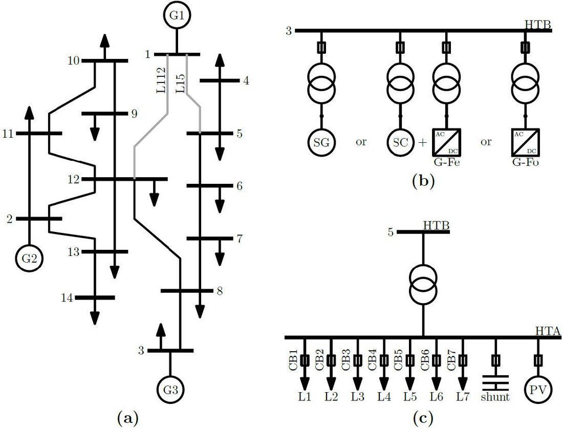
Figure 1 - (a) Single-line diagram (SLD) of French isolated power system “Île du Steak au Poivre”; (b) Illustration of Bus 3 containing the different possible power plants; (c) Detailed representation of Bus 5, composed of seven sheddable general loads, one bank of shunt capacitors, and one PV plant.
Furthermore, each HTA bus is equipped with an under-frequency load shedding (UFLS) protection scheme, of which the block diagram is illustrated in Figure 2. The electric frequency (?) and its rate of change (??) are estimated from a PLL and filtered using two cascaded first-order filters. These signals are processed into an algorithm to determine the feeders that should be shed by acting on the breakers CB1 to CB7.
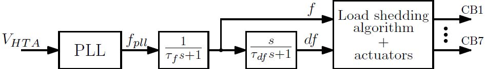
Figure 2 - Block diagram of under-frequency load shedding (UFLS) protection scheme
2.2. Synchronous machine-based sources
As illustrated in Figure 3, two types of synchronous machine-based sources are used in this work: synchronous generators, and synchronous condensers. The detailed control scheme of hydro generators cannot be disclosed due to confidentiality reasons, however, similar structures can be found in [12]. Regarding the synchronous condensers, the only structural difference with the generators is that they do not have a speed governor and turbine.
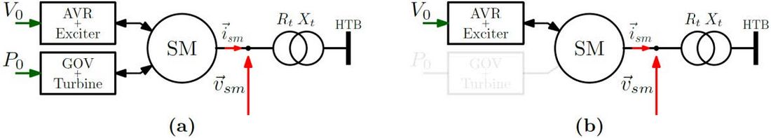
Figure 3 - Structure of synchronous machine-based assets. (a) Synchronous generator; (b) Synchronous condenser
2.3. Power electronics-based sources
The power electronics topology of BESS is illustrated in Figure 4. The inverter is interfaced with the ac grid with an inductive filter and a transformer. Regarding the dc side, the battery voltage dynamics are neglected. The presented structure is considered for either grid-feeding or grid-forming BESS. Examples of structures can be found in [12]–[15]. The macroblocks of the control strategies used in this study are illustrated in Figure 5a, and Figure 5b, respectively.

Figure 4 - Power electronics interface of battery energy storage systems (BESS) controlled either in grid-feeding or grid-forming mode
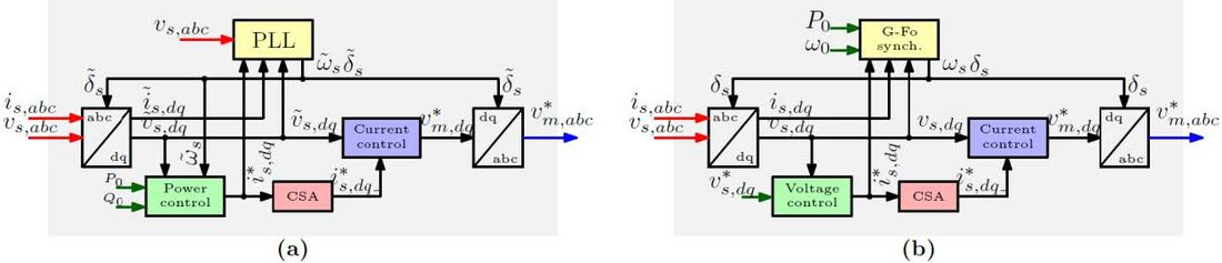
Figure 5 - Structure of (a) grid-feeding control strategy; (b) grid-forming control strategy
3. System stability after a major outage
The French government has decided through decrees that electric generation of isolated systems will fully be derived from renewable energy resources, suppressing progressively all classic fuel-based generation [16], [17]. The deployment of flexibilities such as BESS is expected to mitigate the intermittence of variable renewable energies, and to help the overall stability of the system [18]. Other assets as synchronous condensers can also be used to ensure grid stability [19], [20].
This paper assesses the stability of the Île du Steak au Poivre system after a major outage, the loss of generation site G1 through the disconnection of transmission lines L112 and L15, represented in grey, in Figure 1a. In absolute terms, the loss of G1 corresponds to half of the total generation (120 MW), 54% of power the total power reserve (94 MW/Hz) and 35% of the total kinetic energy (271 MWs).
Aligned with the strategic approach of EDF SEI, scenarios with considerable penetration of PV and combining different types of flexibilities are considered. The Reference scenario represents the current state of this isolated grid with 30% of peak PV generation, and all three generation sites based on synchronous generation. In the other scenarios, the instantaneous penetration ratio of PV corresponds to 50% of the total generation. In Variant 1 (SC + GFe), the fuel-based generation of G2 and G3 is replaced with a combination of synchronous condensers and grid-feeding BESS. Since, as opposed to large power systems, inertia and active power reserve in isolated systems are very limited, being key parameters to guarantee the good behaviour of the system, they are equivalent to those found in the Reference scenario. Variants 2a and 2b (GFo) respectively consider oversized and undersized grid-forming BESS as a replacement of fuel-based generation of G2 and G3. Grid-feeding BESS of Variant 1 are replaced with grid-forming BESS in Variant 3a/b (SC + GFo), providing additional 144 MWs of “inertia”. Table 1 and Figure 6 summarise the aforementioned scenarios, and the active power profiles found before the outage.
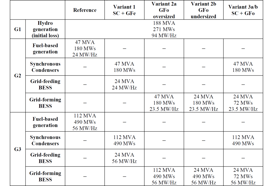
Table 1 - Scenarios considered in the stability study of the Île du Steak au Poivre system
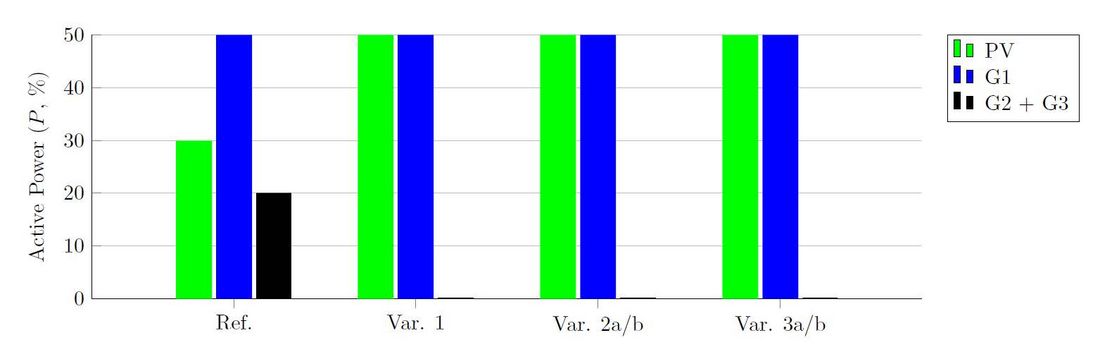
Figure 6 - Initial active power profile of PV and generation sites G1, G2 et G3 for each considered scenario
3.1. Reference scenario
Figure 7 illustrates the evolution of the COI frequency, and HV voltages of the remaining generation sites (Buses 2 and 3) and the electrically furthest loads (Buses 4 and 10) for the Reference scenario after the loss of G1. The classic dynamics of synchronous generators can be observed in the behaviour of the COI frequency.
The dynamics of HV voltages result from different phenomena. At first, a voltage dip due to the network reconfiguration is observed. Subsequently, system voltages undergo a fast increase mainly because of UFLS action, where reactive injection of shunt capacitors supersedes the absorption of the remaining loads. Finally, the dynamics of the voltage regulations of the synchronous generators is observed.
A focus on the action of the UFLS protection scheme of Bus 10 is illustrated in Figure 8. It can be observed that the breaker of the first feeder (CB1) has been triggered following the detection of RoCoF below -2 Hz/s, and those of the second and third feeders (CB2 and CB3) following the detection of frequency under 48.2 and 47.9 Hz, respectively. It is highlighted that, due to the relatively low inertia of isolated systems comparing to interconnected ones, thresholds for UFLS protection scheme are adapted for the operation of the former. The impact of the UFLS action over the HV voltage is also ratified in Figure 8.
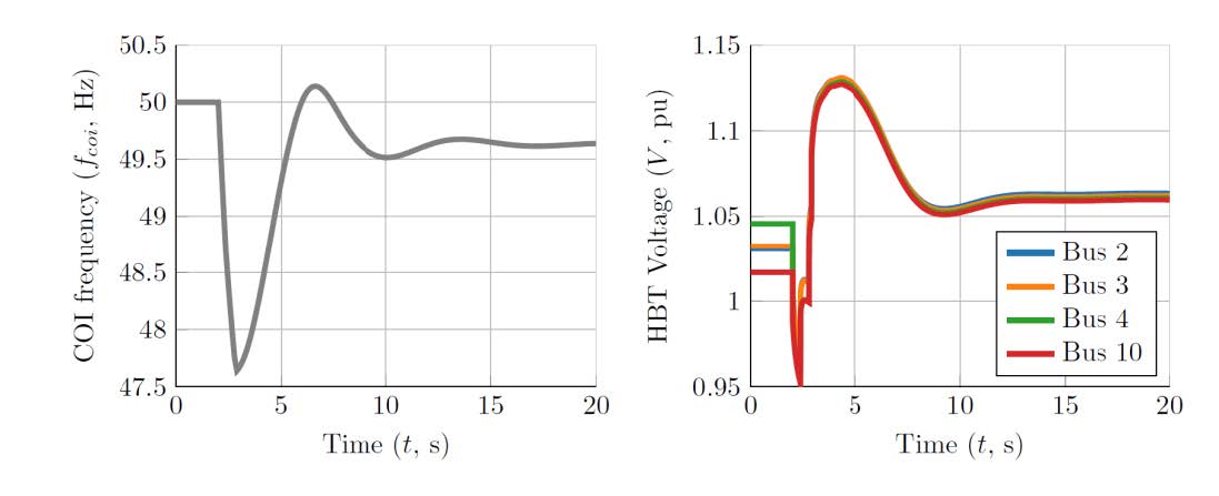
Figure 7 - Evolution of the COI frequency (left) and HV voltage of buses 2, 3, 4 and 10 (right) after the loss of generation site G1 (Reference scenario)
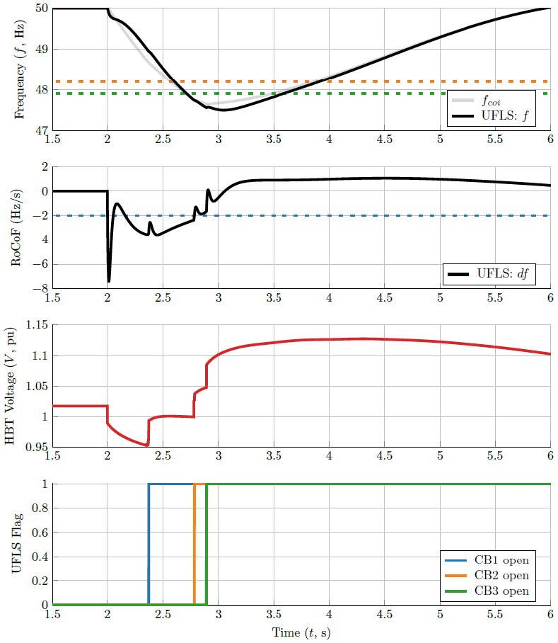
Figure 8 - Action of under-frequency load shedding protection scheme of Bus 10 (Reference scenario). Opening of CB1, and CB2 and CB3 by RoCoF and under-frequency, respectively (thresholds indicated by dashed lines)
3.2. Variant 1: Synchronous condensers and grid-feeding BESS
In Variant 1, with the replacement of the fuel-based generation of G2 and G3 with a combination of synchronous condensers and grid-feeding BESS, dynamics are slightly improved. A comparison of frequency and voltage behaviours of the current scenario and the Reference one is provided in Figure 9.
Regarding frequency dynamics, since the equivalent inertias of both scenarios are equivalent, the RoCoF immediately after the incident are also the same. However, thanks to the rapid response of the frequency reserve of the BESS – i.e. first order response with 350 ms settling time – frequency nadir is slightly improved. Therefore, the dominant behaviour of the frequency is more damped, not presenting oscillations to regain steady state. As in the Reference scenario, and for the same reasons, three feeders of each system load have been shed.
The replacement of synchronous generators with a combination of synchronous condensers and grid-feeding BESS does not appear to have a significant impact on the behaviour of system voltages.
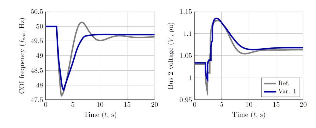
Figure 9 - Comparison of the COI frequency (left) and HV voltage Bus 2 (right) after the loss of generation site G1 obtained with the Reference and Variant 1 scenarios
3.3. Variant 2a and 2b: 100% grid-forming BESS
Instead of replacing fuel-based generators with synchronous condensers and grid-feeding BESS, Variant 2 proposes only the deployment of grid-forming BESS, providing both the same equivalent inertia and power-frequency characteristics of the previous scenarios. Two different scenarios are considered in Variant 2 per se. Oversized and undersized BESS are used in Variant 2a and 2b, respectively.
Frequency and voltage behaviours are significantly improved in Variant 2a. A comparison with the results of Variant 1 is given in Figure 10. Since after the loss of G1 there are only grid-forming BESS connected to the system, differently than the precedent scenarios, the COI frequency displays a first-order dynamic. As a result of the same equivalent inertia as in the precedent scenarios, the initial RoCoF is the same as observed before, and therefore, the first feeders of all system loads have been disconnected following the detection of low RoCoF. However, due to the improvement of frequency behaviour, under-frequency protections have not been triggered, thus bringing the system frequency to a different equilibrium point.
It should be highlighted that a load shedding protection scheme based on RoCoF is used to avoid fast frequency variations, resulting in deep nadirs, and possibly, a frequency collapse. The use of this mechanism is justified for the Reference scenario and Variant 1. However, since in the current scenario the COI frequency displays a first-order dynamic, the RoCoF-based load shedding protection scheme is unnecessary, and even inopportune since grid-forming BESS have sufficient capacity to provide the whole active power mismatch and thereby avoid load shedding.
Because of the fast voltage control of grid-forming BESS, the voltage behaviour of the system is also different when compared to precedent cases. The sudden current draw due to network reconfiguration triggers transiently the current limitation algorithm of grid-forming BESS, accentuating voltage dip, which reaches 0.65 pu. However, since the BESS are oversized, this phenomenon lasts only for tens of milliseconds. As in the precedent scenarios, it is possible to observe a voltage increase following the UFLS action. Furthermore, it is highlighted that, due to the faster voltage control of grid-forming BESS comparing to classic synchronous generators, a better support is provided for PV plants, which can trip protections due to long periods of overvoltage.
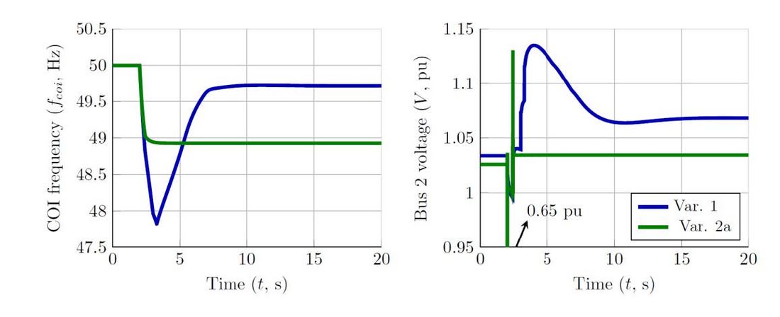
Figure 10 - Comparison of the COI frequency (left) and HV voltage Bus 2 (right) after the loss of generation site G1 obtained with Variants 1 and 2a
In Variant 2b, grid-forming BESS are undersized with a rated power of 24 MVA/each. Differently than in Variant 2a, the BESS cannot support the initial current draw and the current limitation algorithm is permanently triggered, resulting in a low steady-state voltage in all system buses. Since system loads display dependency with voltage levels, the consumption drastically reduces, and therefore, the COI frequency does not display a consequent drop, stabilising just below 49.75 Hz. Consequently, no feeders have been shed by the UFLS protection scheme. Figure 11 illustrates a comparison between Variants 2a and 2b.
In the current scenario, the reduction of the system voltage – which is a result of the current limitation strategy of grid-forming BESS – hinder the proper operation of the UFLS protection scheme, rendering the system inoperable. Variant 2b cannot be considered as a candidate solution as the observed low voltage levels would trigger the under-voltage protection of the grid-forming BESS (not modelled in this work) resulting in a system blackout.
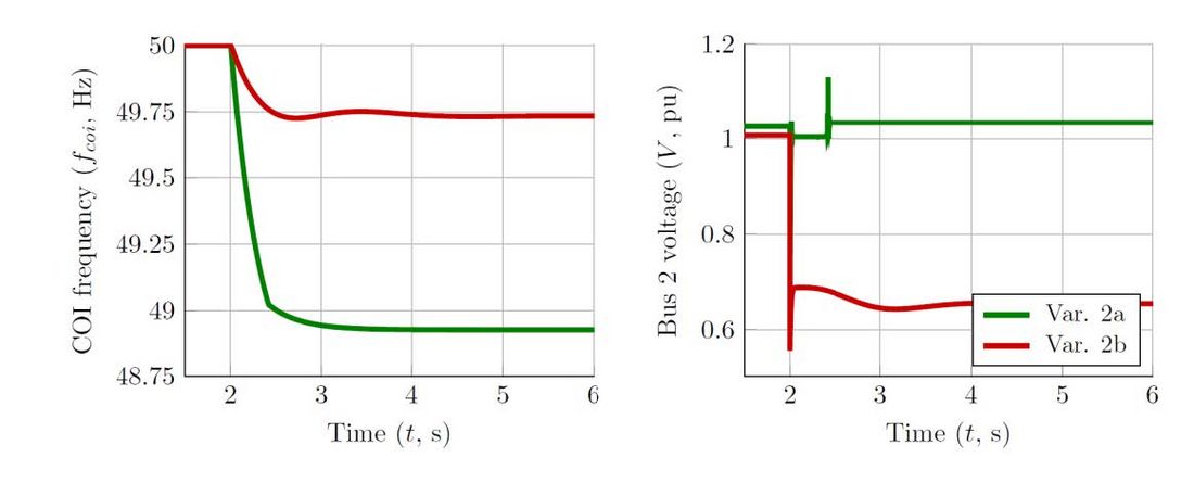
Figure 11 - Comparison of the COI frequency (left) and HV voltage Bus 2 (right) after the loss of generation site G1 obtained with Variants 2a and 2b
3.3. Variant 3a/b: Synchronous machines and grid-forming BESS
In Variant 3a/b, grid-feeding BESS from Variant 1 are replaced with grid-forming BESS, resulting in a combination of synchronous condensers and grid-forming BESS. In this scenario, the grid-forming BESS provide additional 144 MWs of “inertia”, resulting in 814 MWs after the loss of G1.
It has been identified in the literature that the current saturation algorithm in grid-forming inverters in systems with synchronous machines could lead to loss of synchronism [21]–[24]. To circumvent it, an adaptation of the measurement of active power in the grid-forming control is proposed in [25]. Instead of using the measurement of output voltage (??,??) and current (??,??), as given in Eq. (1), the “unsaturated power” (??????) is calculated using the measurement of output voltage and the unsaturated current reference (), as given in Eq. (2). As a result, even if the inverter is saturated, the synchronisation algorithm treats it as unsaturated, preventing synchronism losses.
(1)
(2)
The grid-forming BESS of Variant 3a and 3b implement the classic, and the modified approach for active power measurement, respectively. Figure 12 compares the frequency behaviour of these sources in both variants. It can be observed that, in Variant 3a, after a certain period saturated, the grid-forming BESS break the synchronism with the system, starting to oscillate. On the contrary, in Variant 3b, the frequencies of grid-forming BESS behave as expected, even though they operate saturated for a long period of time. Even though the sources eventually become resynchronised in Variant 3a, the observed behaviour cannot be accepted in real power systems, since the power oscillations can jeopardise the stability of the grid and the integrity of its elements.
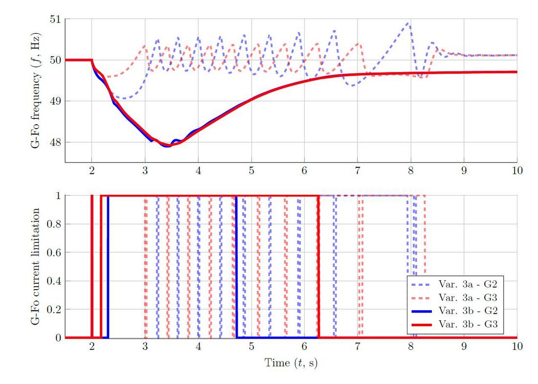
Figure 12 - Comparison of the grid-forming frequency behaviour (top) and activation of its current limitation algorithm (bottom) obtained with Variants 3a and 3b
A comparison of the COI frequency obtained with Variant 1 and Variant 3b is provided in Figure 13. It can be noted that, despite the 144 MWs of additional inertia, the improvement of the frequency behaviour, especially on the initial RoCoF, is almost negligible. This can be explained by the fact that the grid-forming BESS are in current limitation mode (Figure 12) and, despite the additional inertia, they are not able to provide much more active power to the grid when compared with grid-feeding BESS (Figure 13).
It is worth reminding that, as opposed to synchronous machines, inertia on power electronics-based sources is a control parameter, and it only is effective if the source is not limited in current (or power).
Nevertheless, it can be observed in Figure 14 that, even limited, grid-forming BESS is able to improve system dynamics, especially system voltage, when compared to previous variants. However, it is emphasised that, in normal conditions, the supplementary inertia provided by grid-forming BESS would also display a positive impact on the frequency behaviour of the system, especially the initial RoCoF.
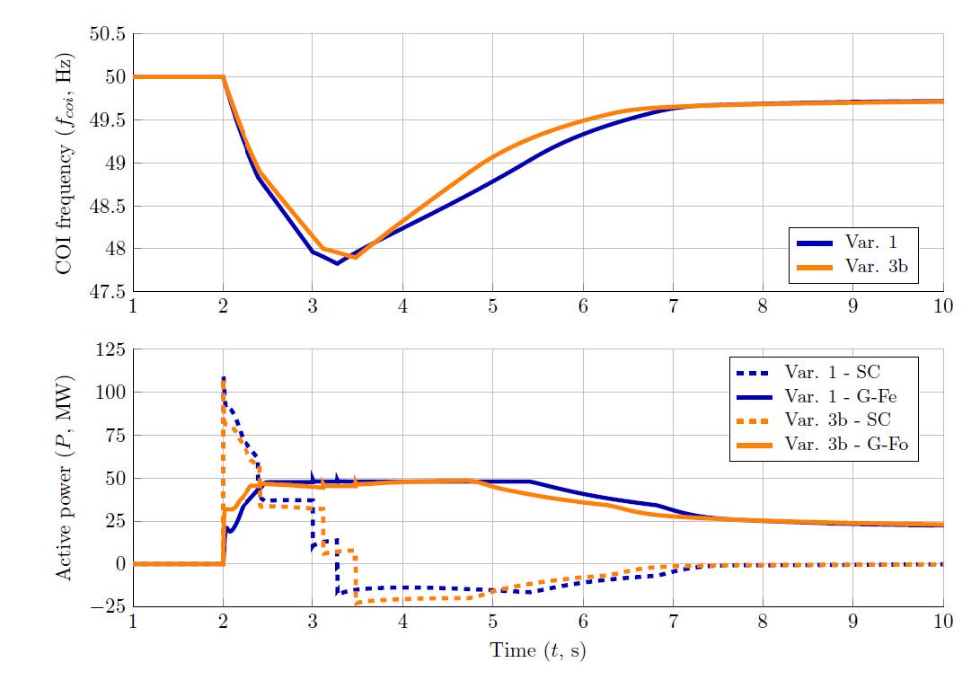
Figure 13 - Comparison of the COI frequency (top) and total active power provided by the synchronous condensers and BESS (bottom) after the loss of generation site G1 obtained with Variants 1 and 3b
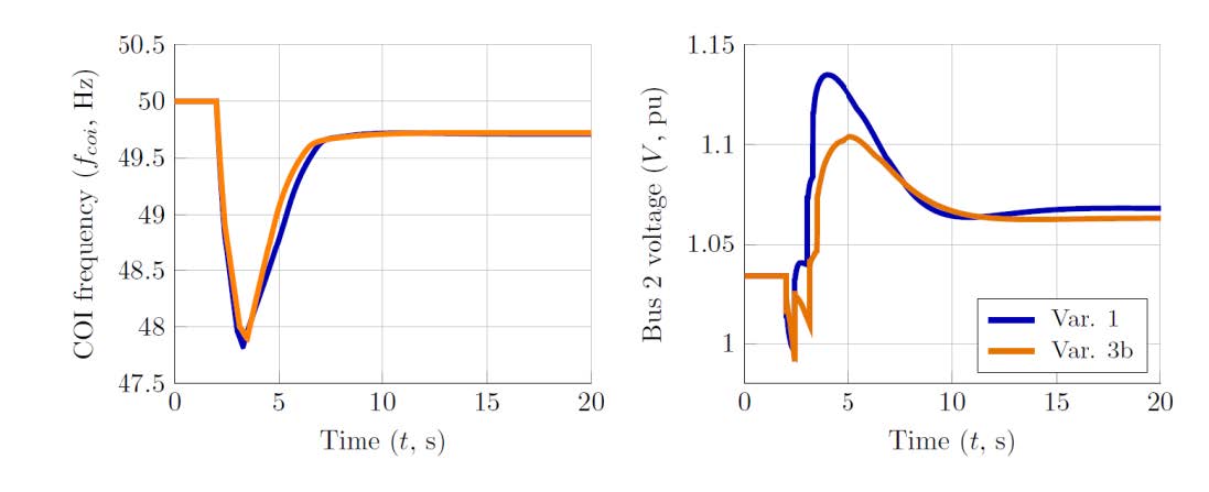
Figure 14 - Comparison of the COI frequency (left) and HV voltage Bus 2 (right) after the loss of generation site G1 obtained with Variants 1 and 3b
4. Summary of the main findings and perspectives
This study has compared different scenarios to mitigate fuel-based sources, achieving 100% of renewable energy generation in a French isolated power system. BESS in both grid-feeding and grid-forming modes, as well as synchronous condensers, have been considered as solutions to replace the fuel-based generation.
For a scenario be considered as a valid solution, the system should resist a major generation loss without disturbing the UFLS protection scheme, displaying abnormal steady-state equilibrium point, or breaking – even transiently – the synchronism between its sources. Three variants have fulfilled these requirements. A comparison of the dynamics of their COI frequencies and voltages with the Reference scenario is illustrated in Figure 15.
All three variants present improved dynamics when compared with the Reference scenario. Variant 2a with 100% oversized grid-forming BESS displays the best behaviour of all solutions. In this scenario, the first-order dynamic of the COI frequency, due to the absence of a frequency nadir, allows for more consumers to remain connected after the outage, by shedding fewer feeders. Voltage behaviour is also improved in this variant, presenting much faster dynamics when compared with the other solutions. However, considering the current industrial scenario, a 100% oversized grid-forming BESS-based solution is also the least realistic between them.
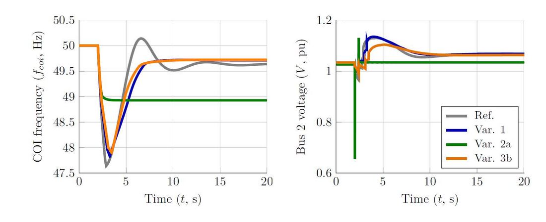
Figure 15 - Evolution of the COI frequency (left) and HV voltage Bus 2 (right) after the loss of generation site G1 for the acceptable scenarios
Variant 2b with an undersized grid-forming BESS and the proposed control structure could not ensure an acceptable steady-state voltage level. Further work will focus on different BESS power conversion architectures and control strategies to try and mitigate this issue and allow a smooth operation of under-frequency load shedding.
Variants 1 and 3b are both based on a combination of synchronous condensers and BESS, the control strategy of the battery being the only difference between them; grid-feeding and grid-forming, respectively. The dynamics observed with both solutions are comparable, although slightly better – especially regarding voltage dynamics – with grid-forming BESS. It is reminded that, if grid-forming BESS are not saturated, they can provide additional inertia to the system. However, it is also highlighted that, compared to the grid-feeding strategy, it is more difficult to perform current limitations in inverters with grid-forming strategy, and the robustness and effectiveness of the proposed strategies are still under investigation.
As a grid operator, EDF SEI considers grid-forming control of BESS to be a very valuable solution to increase VRE rates while ensuring system stability under any circumstances. However, there are still challenges under investigation to clearly specify the behaviour of this new class of assets. Current limitation strategies are part of these challenges. Future works could reveal that the optimal limitation strategy is system-specific, i.e. depending on grid topology and on the possible grid incidents, or even asset-specific, i.e. depending on the point of connection of the grid-forming BESS.
References
- EDF, “Open data EDF Corse & Outre-mer.” https://opendata-corse-outremer.edf.fr/pages/home0/ (accessed Nov. 15, 2021).
- F. Gonzalez-Longatt, J. M. Roldan-Fernandez, H. R. Chamorro, S. Arnaltes, and J. L. Rodriguez-Amenedo, “Investigation of inertia response and rate of change of frequency in low rotational inertial scenario of synchronous dominated system,” Electron., vol. 10, no. 18, 2021, doi: 10.3390/electronics10182288.
- U. Rudez and R. Mihalic, “RoCoF-based Improvement of Conventional Under-Frequency Load Shedding,” in 2019 IEEE Milan PowerTech, Jun. 2019, no. June, pp. 1–5, doi: 10.1109/PTC.2019.8810438.
- EU-SysFlex, “Deliverable 3.1: Product Definition for Innovative System Services,” EU, 2019.
- F. Milano, F. Dorfler, G. Hug, D. J. Hill, and G. Verbic, “Foundations and Challenges of Low-Inertia Systems (Invited Paper),” in 2018 Power Systems Computation Conference (PSCC), Jun. 2018, pp. 1–25, doi: 10.23919/PSCC.2018.8450880.
- ENTSO-E, “Technology Factsheets,” Brussels, 2021.
- ENTSO-E, “High Penetration of Power Electronic Interfaced Power Sources and the Potential Contribution of Grid Forming Converters,” Brussels, 2020.
- D. Prasetijo, W. R. Lachs, and D. Sutanto, “A new load shedding scheme for limiting underfrequency,” IEEE Trans. Power Syst., vol. 9, no. 3, pp. 1371–1378, 1994, doi: 10.1109/59.336128.
- G. Delille, L. Capely, D. Souque, and C. Ferrouillat, “Experimental validation of a novel approach to stabilize power system frequency by taking advantage of Load Voltage Sensitivity,” in 2015 IEEE Eindhoven PowerTech, Jun. 2015, pp. 1–6, doi: 10.1109/PTC.2015.7232697.
- O. Schömann et al., “Experience with Large Grid-Forming Inverters on Various Island and Microgrid Projects,” 4th Int. Hybrid Power Syst. Work., no. May, pp. 0–4, 2019.
- J. H. Eto et al., “Research Roadmap on Grid-Forming Inverters,” NREL Rep., 2020.
- G. S. Pereira, “Stability of power systems with high penetration of sources interfaced by power electronics,” Centrale Lille, 2020.
- T. Qoria, “Grid-forming control to achieve a 100% power electronics interfaced power transmission systems,” 2020, [Online]. Available: https://pastel.archives-ouvertes.fr/tel-03078479.
- M. Paolone et al., “Fundamentals of power systems modelling in the presence of converter-interfaced generation,” Electr. Power Syst. Res., vol. 189, no. April, p. 106811, 2020, doi: 10.1016/j.epsr.2020.106811.
- A. Monti, F. Milano, E. Bompard, and X. Guillaud, Converter-Based Dynamics and Control of Modern Power Systems, 1st ed. Elsevier, 2020.
- République Française, “Décret no 2017-530 du 12 avril 2017 relatif à la programmation pluriannuelle de l’énergie de La Réunion,” J. Off. la République Française, no. NOR : DEVR1701352D, p. 182, 2017.
- République Française, “Décret no 2015-1697 du 18 décembre 2015 relatif à la programmation pluriannuelle de l’énergie de Corse,” J. Off. la République Française, no. NOR : DEVR1527419D, p. 86, 2015.
- MIGRATE, “The Massive InteGRATion of power Electronic devices: Enabling the energy transition by providing solutions for the technological challenges,” TenneT TSO GmbH, EU, 2020.
- A. Di Giulio et al., “Increased grid performance using synchronous condensers in multi in-feed multi-terminal HVDC System,” CIGRE Sess. 45, p. 8, 2014, doi: 10.13140/2.1.1829.0241.
- H. Biellmann et al., “The benefits of implementing Synchronous Compensators in grids with high penetration of Renewables,” in Cigre, 2020, p. 16.
- H. Xin, L. Huang, L. Zhang, Z. Wang, and J. Hu, “Synchronous Instability Mechanism of P-f Droop-Controlled Voltage Source Converter Caused by Current Saturation,” IEEE Trans. Power Syst., vol. 31, no. 6, pp. 5206–5207, 2016, doi: 10.1109/TPWRS.2016.2521325.
- J. Chen, F. Prystupczuk, and T. O’Donnell, “Use of voltage limits for current limitations in grid-forming converters,” CSEE J. Power Energy Syst., vol. 6, no. 2, pp. 259–269, 2020, doi: 10.17775/CSEEJPES.2019.02660.
- E. Rokrok, T. Qoria, A. Bruyere, B. Francois, and X. Guillaud, “Transient Stability Assessment and Enhancement of Grid-Forming Converters Embedding Current Reference Saturation as Current Limiting Strategy,” IEEE Trans. Power Syst., vol. 37, no. 2, pp. 1519–1531, Mar. 2022, doi: 10.1109/TPWRS.2021.3107959.
- X. Wang, M. G. Taul, H. Wu, Y. Liao, F. Blaabjerg, and L. Harnefors, “Grid-Synchronization Stability of Converter-Based Resources—An Overview,” IEEE Open J. Ind. Appl., vol. 1, no. August, pp. 115–134, 2020, doi: 10.1109/ojia.2020.3020392.
- K. V. Kkuni and G. Yang, “Effects of current limit for grid forming converters on transient stability: analysis and solution,” Jun. 2021, [Online]. Available: http://arxiv.org/abs/2106.13555