Oscillatory Interaction Between Large Scale IBR and Synchronous Generators in the NEM
AUTHORS
E. FARAHANI, P. F. MAYER, J. TAN, F. SPESCHA, M. GORDON
Australian Energy Market Operator (AEMO), Australia

Summary
Oscillatory modes in the Australian National Electricity Market (NEM) are changing due to network topology changes, the addition of new generations, and the retirement of synchronous generators from the market. These factors influence the frequency and damping of the oscillations.
This paper is concerned with the interaction of Inverter-Based Resource (IBR) plant-level controls with an oscillatory mode in the NEM. The 3.5 rad/s (≈0.5 Hz) mode involves synchronous generators in Queensland (QLD) and Victoria (VIC) oscillating against generators in New South Wales (NSW) and South Australia (SA) spanning a power system that covers the 5000 km eastern seaboard of Australia. The recent integration of large-scale IBRs on critical system interconnectors has shown the potential to further deteriorate this oscillatory instability resulting in the need for additional tuning of IBRs control systems. This phenomenon may occur if the new IBR installations lack control bandwidth at the same frequencies as system modes.
Results of two case studies on oscillatory stability investigations carried out by the Australian Electricity Market Operator (AEMO) using the wide-area EMT model are presented in this paper. First, it is shown that with modification of the Grid Following (GFL) IBR controls, the negative influence on the system mode could be mitigated. AEMO also did investigate the hypothetical application of a commercially available Grid Forming (GFM) Virtual Synchronous Generator (VSG) system. VSG settings chosen without consideration of the existing system are shown to have the potential to exacerbate existing oscillatory instabilities. In both cases, the simulations show that better system-wide damping could be obtained only when there is careful consideration of the electrical location of the IBR, as well as the settings of the IBR controllers regardless of the IBR technology.
Keywords
Power system stability - Small signal analysis - oscillatory modes - systems - renewable - grid forming - oscillations1. Introduction
Oscillatory instability is one of the major concerns to power system operation in the NEM. The NEM comprises the interconnected system of Queensland, New South Wales, Victoria, South Australia and Tasmania, with HV transmission levels ranging from 110 kV to 500 kV. The system has numerous AC as well as HVDC interconnectors as illustrated in Figure 1 and it spans 5000 km with a maximum demand of approximately 35GW. AEMO is an independent system and market operator responsible for power system security under the provisions of the National Electricity Rules (NER). Since 2018, the NEM has faced operational challenges due to the large uptake of IBRs and operational reduction in participation or decommissioning of large conventional synchronous generators [1]. Most IBRs in the NEM are located in remote areas with limited transmission capacity, remote from load centres and conventional Synchronous Generators (SG). The electrical distance of IBRs from stronger parts of the network together with the large size of some IBR projects has contributed to specific weak operating arrangements in terms of system strength. New market initiatives have been conducted by the Australian Energy Market Commission (AEMC) [2] to address this problem via an update to system strength grid code requirements. Additionally, a simultaneous reduction in the number of online conventional generators has resulted in a decline in the system inertia, fault levels, and power system stability robustness in consideration of conventional power system stability.
The possible adverse impacts of control systems of IBRs on the grid oscillatory modes were investigated in [3]. As discussed in [3] IBR control parameters can significantly improve mode damping but also create unstable modes if not tuned properly. The influence of the IBR control parameters on the grid stability will be magnified as the system becomes weaker in terms of system strength [4]. This paper presents the results of two case studies, highlighting the adverse interaction between IBRs control systems and one of the oscillatory modes in NEM, experienced during grid connection integration at the critical location in the grid. Both experiences indicated that inappropriate parameter settings of the IBRs can lead to a significant reduction in damping properties of at least one of the oscillatory modes, regardless of the IBR technology. Grid inertia decline can also lead to changes in the characteristics of the grid oscillatory modes and their sensitivities to operational conditions [5]. Therefore, system integration studies of emerging IBRs in the NEM frequently involve the exposure of electromechanical modes (for conventional generators) and electrical control instabilities of power electronic connected devices [6].
1.1. Oscillatory modes in the NEM
Some of the traditional and well-known oscillatory stability modes in the NEM are the QLD vs SA mode at approximately 0.3 Hz, the ‘I35’ mode comprising QLD/VIC vs. NSW/SA at approximately 0.5 Hz (see Figure 2), the ‘I25’ mode, and a number of other local, intra-station and intra-regional modes that are typically present in AC connected bulk power systems. At present, there is no real-time post-contingent assessment of oscillatory security in the NEM. Instead, offline frequency domain analyses (small signal studies) are relied upon to establish operating transfer limits on critical transmission lines and interconnectors. However, a lack of information on linearized models of IBRs has resulted in greater uncertainties in the frequency domain analysis. Currently, for the mainland system, AEMO uses the Psymetrix Monitor [7] to extract modal damping values from measured system perturbations present in real interregional line flows at various points in the system. This tool cannot be utilized for forward-looking studies.
It is very important to recognize that many existing stabilizing devices, such as Power System Stabilisers (PSS) and Static Var Compensators (SVC), on the NEM, were tuned for the system at the time of their energization or commissioning. In many cases, this can date back more than 20 or even 30 years. However, as seen in [5] the characteristics of some of the critical oscillatory modes can change as inertia declines. Therefore, as the NEM is undergoing an unprecedented number of IBR connections and the rapid decommissioning of conventional synchronous generators, the stabilizing controllers tuned in the past may not be effective for the present power system. Thus, it is prudent that the system operators constantly monitor the damping characteristics of the SGs across the grid as inertia declines and advise the relevant generating systems if they cannot meet NER requirements in terms of damping factors. Then, the generating systems must address the non-compliance via retuning the relevant control systems such as PSS.
1.2. Adverse interaction between an IBR and I35 oscillatory mode
This paper presents an example of a critical control interaction between plant-level controls of a GFL IBR and a system mode. The adverse interaction was identified during studies of a large-scale IBR connection into an HV transmission interconnector corridor. The oscillatory instability was observed during simulations using a wide-area EMT model. Traditional small signal stability tools have been unable to identify these types of interactions with the available models. This paper shows how the interaction of IBR controls can contribute to oscillatory instability across the NEM, especially when IBRs are at locations susceptible to power system oscillations. While small signal stability analysis is based on the assumptions of small perturbations and linearised models, the composition of IBRs and conventional generators in the transitioning power system requires greater assessment effort which may include a combination of analytical tools. In other words, a diversity of analyses is of particular importance when IBR linearized model information may not be available, validated, or provide the most up-to-date plant representation.
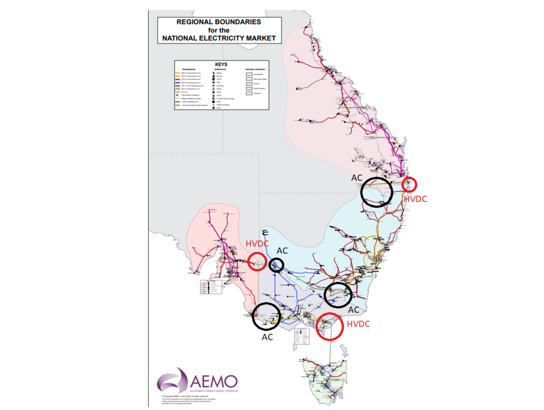
Figure 1 - Overview of the NEM managed by AEMO with indications of HV AC and HVDC interconnectors between regions (publicly available map from aemo.com.au)
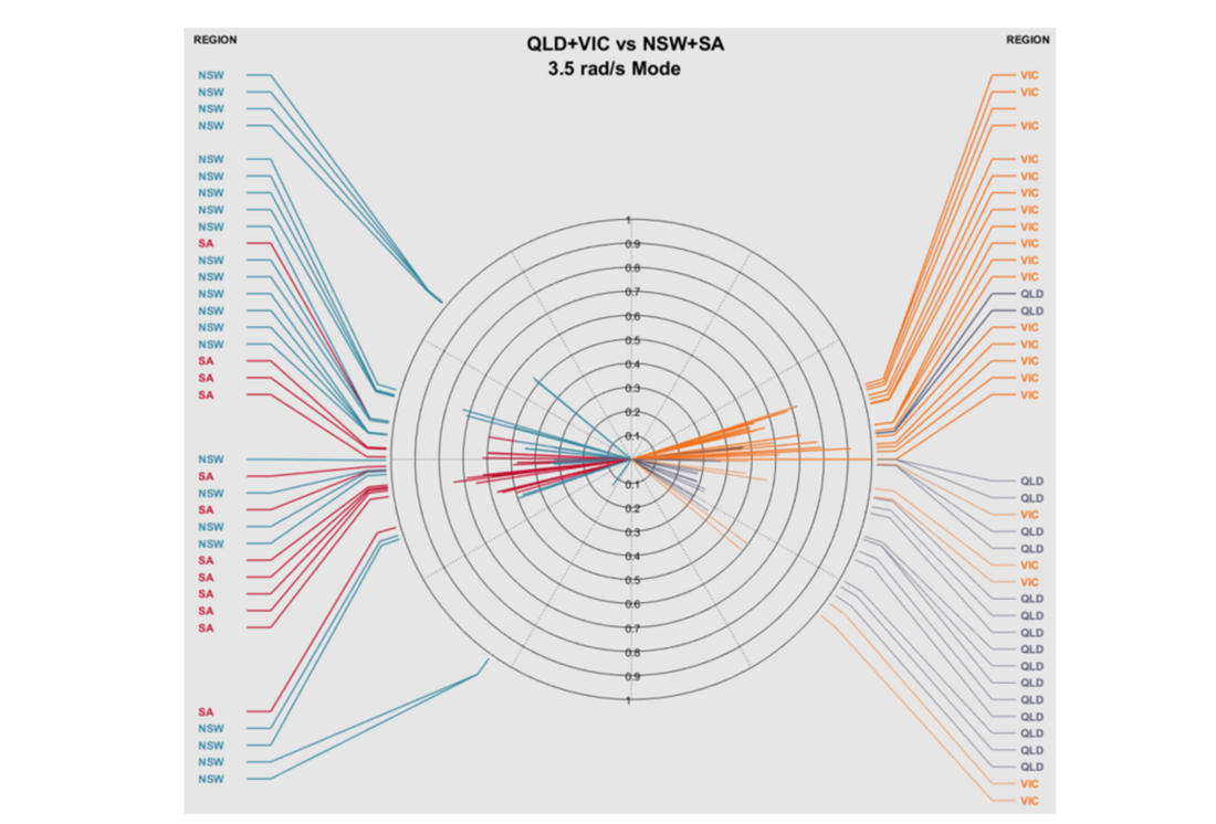
Figure 2 - NEM oscillatory mode between QLD/SA vs NSW/SA (eigenvectors for synchronous machines in each NEM region)
The impact of a large-scale IBR plant on power system oscillatory instability in this paper could not be captured with conventional small signal assessment tools. The actual control and characteristics associated with the plant level control hierarchies, including communication delays were simulated in an EMT wide-area model. Results of the EMT simulation showed that the IBR plant exacerbated inter-area oscillations between two clusters of synchronous generators. The participation of the IBR plant controls in this mode resulted in oscillations lasting for more than 30 seconds which exceeded the damping requirements stipulated in the NER.
Our discussion is further expanded by presenting examples of the stabilizing characteristics of a GFM VSG Battery Energy Storage System (BESS). It is shown that the configuration options available in a VSG solution provide flexibility that can either dampen system oscillations or, if inappropriately configured, exacerbate them.
1.3. Converter-driven stability
Converter-driven stability is an emerging topic in power system stability that covers a wide range of frequencies, including slow interactions with electromechanical systems [9]. Sustained oscillations in power, reactive power, and voltage are among the most common power system stability challenges recently experienced in Australia. For inverter-based plants, these instabilities may be manifested from the lower to higher frequency ranges (instabilities at 0.25 Hz, 6-8 Hz to 19 Hz have been observed in the NEM). Example of problems in the real power system, including its solutions, was documented in [10]
1.4. Application of Grid Forming VSG across the NEM
Integration of Grid Forming IBRs is still in its inception stage in the NEM. As of 2022, there are no grid forming wind nor solar installations. Currently, there is one GFM BESS generating system equipped with VSG and another GFM BESS VSG approved for connection, with expected commissioning in early 2023. Both are located in remote parts of the power system. While the benefits of GFM BESS and non-grid forming BESS devices in general have shown to provide sufficiently fast frequency responses and adequate reactive support capabilities, for the overall effectiveness of VSGs, it is important that they are installed at critical system locations where their full functionality can be utilized for the benefit of the overall system stability. In this paper, we present the potential oscillatory stability benefits of a properly tuned VSG in a location known to be sensitive to oscillatory stability. The importance of wide-area studies is highlighted as we explore the impact of VSG inertia emulation capabilities and the overall benefits of the response across the NEM.
2. Power System Model
Driven by the complexity of the interconnected system and shortfalls associated with availabilities of IBR’s linearized models for oscillatory stability assessments, the studies in this paper have focused on using the state of the art full NEM EMT model. The wide-area EMT model includes more than 3000 buses and in excess of 300 detailed site-specific IBR models. The model contains all the transmission lines and transformers, the distribution transformers and underlying distribution networks including their equivalents. Furthermore, AEMO has custom-built unit specific, dynamic models of all critical synchronous power stations in the NEM.
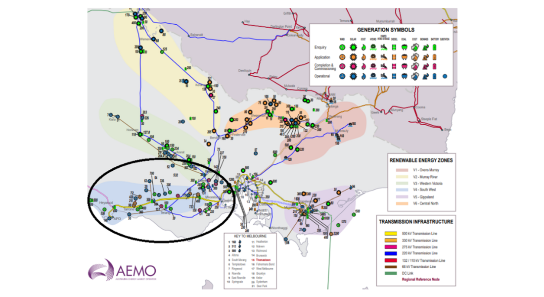
Figure 3 - Power system map indicating 500/220 kV area of interest and Victorian-South Australian HV interconnector near Haywood (publicly available map from aemo.com.au)
In earlier works and prior to the addition of large-scale IBRs, sensitivity to oscillatory instability across QNI and SA-VIC interconnector was analysed in [11] The SA-VIC 275kV interconnector stretches more than 400km from Heywood in Victoria to Tailem Bend in South Australia. Its system-normal transfer is limited to approximately 600 MW in each direction due to stability reasons. Since 2016 the interconnector on the Victorian side has had a few large-scale IBR (wind farm) connections collectively exceeding 1500 MW of generation capacity. See Figure 3 for the study area of interest. All IBRs in the network case are modelled as site-specific client user models with detailed representation of inverters and plant-level controls.
3. Stability investigation
3.1. Impact on oscillations from a grid following IBR
The grid disturbance for this investigation occurred on a 500 kV system. The 500 kV transmission line is highlighted by a black ellipsoid in Figure 3. As shown in Figure 3, the 500 kV double-line circuit connects SA to the central part of VIC. In this disturbance, one of the 500 kV circuits was disconnected as a result of a two-phase-to-ground fault. The fault An IBR plant has been identified as the largest contributor to exacerbating the oscillatory instabilities on the interconnector, where oscillations exceeding 30 seconds have been observed across the NEM power system, see Figure 4. The IBR was equipped with grid-following technology (GFL). Initial investigations indicated that synchronous generators in Queensland (QLD) and Victoria (VIC) formed a coherent group oscillating against the synchronous generators in New South Wales (NSW) and South Australia (SA), see Figure 5 to Figure 7. Further study revealed that contributions from SGs in SA and VIC toward the 0.5 Hz inter-area oscillatory mode were more significant than the SGs in NSW and QLD. In other words, the nearest generators were swinging against each other.
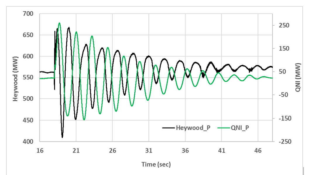
Figure 4 - Heywood and QNI oscillation following 500 kV disturbance at Heywood
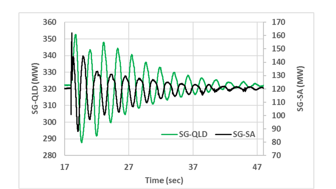
Figure 5 - Oscillation of one synchronous generator in SA (SG-SA) vs one synchronous generator in QLD (SG-QLD)
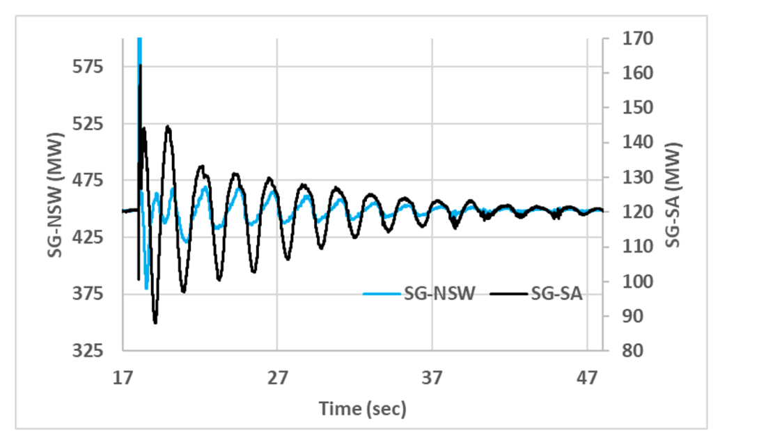
Figure 6 - Oscillation of one synchronous generator in SA (SG-SA) vs one synchronous generator in NSW (SG-NSW)
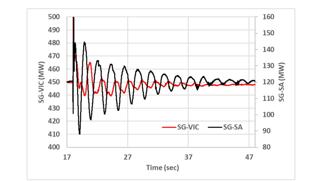
Figure 7 - Oscillation of one synchronous generator in SA (SG-SA) vs one synchronous generator in VIC (SG-VIC)
Compounding the inter-area electromechanical oscillations, the IBR plant has also shown inadequate performance associated with dynamic voltage control capabilities at the same frequencies. Figure 8 shows the overlay of reactive power injected by that IBR and the voltage at its connection point. From Figure 8 it is obvious that the IBR is not controlling these voltage oscillations at its point of connection as its injected reactive power is completely in phase with the voltage at its point of connection. This behaviour excites the existing I35 (0.5 Hz) oscillatory mode. This issue will be explained in more detail below.
Following careful redesign and tuning of the IBR plant-level control systems, a solution has been achieved with damping requirements being met, as shown in Figure 9. It will be discussed in more detailed in Section 3.2.
3.2. The root cause
It is generally assumed that IBR plants will not participate in inter-area electromechanical modes due to the lack of the physical rotating mass, which is directly coupled to the grid. As the control bandwidth of the grid-interfacing inverters is much higher than the frequency range of inter-area oscillations, the risk of an undesirable control interaction at such low frequencies is not obvious. In fact, most studies that examine the interaction of IBR controls on inter-area oscillations focus on the potentially beneficial properties of IBR control and assume that IBRs are connected in close electrical proximity to the SG that they are displacing [6], [12], [13]. These studies generally show a positive impact of IBR on system modes. On the contrary, our experience has been that IBRs are seldom located in proximity to existing SG. In fact, because they require large open spaces, IBR plants tend to be located both physically and electrically far from both population and conventional generation centres, such as coal-fired and hydropower stations.
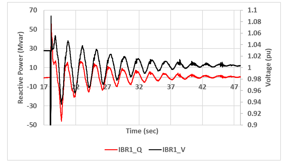
Figure 8 - Inadequacy of IBR in controlling the voltage at its connection point
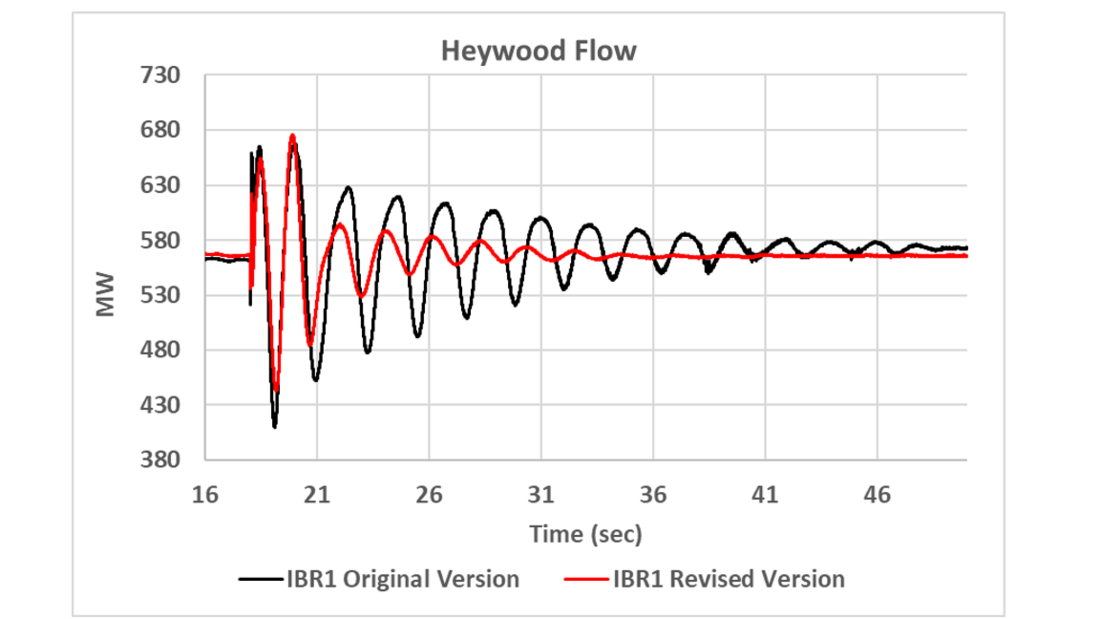
Figure 9 - Comparison of Heywood interconnector performance before and after IBR control system redesign

While the bandwidth of inverter controls is more than sufficient to prevent participation in low-frequency modes, communication delays between controllers within IBR plants tend to be high (in the 100s of ms) and their effect on system stability are seldom considered [14], [15]. In this investigation, when communication channel delays were considered using time-domain EMT simulation, the reactive power controls implemented in the subject IBR were found to be unstable at the same frequency as a known system mode (I35). Furthermore, because of its geographic location along an inter-tie between the two areas involved with the mode, reactive power injection by the IBR would directly influence the flow along the line. Investigations on the influences of FACTS devices on inter-area oscillations have mainly focused on mechanisms for improving stabilization [16]-[18]. The case in this paper shows that the same sensitivity which makes the mid-point of a line an ideal location for damping improvement, also means that an unstable reactive current injection in that location will have an increased detrimental effect on the inter-area power transfer.
The oscillatory instability of concern in this paper is directly related to control issues of a single IBR plant which has tipped the balance of power system stability in the area. The overall cause-effect in the network is complex including the following contributing factors:
Controls: The IBR system has been found to have implemented controls that are inherently unstable (i.e. in isolation of the external system) at the frequencies of concern. Furthermore, the inherent quantization, transport delays for control signals between the plant controller and the inverter, including auxiliary systems, operation mode selections, the speed of response, gains and limiters in the park level control are all contributing factors have been redesigned as part of the project integration. The relevant OEM was notified about the voltage control system instability of the IBR at the frequency of interest and its adverse impact on the 0.5 Hz oscillatory mode. The OEM did further investigations and endeavoured to retune the model and also the associated firmware. As a result of tunning, the voltage control system showed sufficient robustness at 0.5 Hz. The performance enhancement of the voltage control system is highlighted in Figure 9. The black and red traces, respectively, show the MW flow oscillations before and after the tunning process. As depicted in Figure 9, the adverse impact of the IBR of the damping of the oscillatory mode has been significantly mitigated.
Large size of the project relative to system strength: Despite the location on the EHV transmission corridor, the connection can be considered weak on the basis of traditional SCR proxy (Short Circuit MVA/Rated MW). Consequently, voltage sensitivity to power and reactive power changes are prominent [19].
Cumulative effect of IBR: While the interconnection studies of the IBR have exposed its internal control limitations, the studies also highlighted the control integrity of other nearby large-scale IBRs. The contribution and weakness at oscillatory frequency modes from nearby generation plants had gone unnoticed in the past. From that perspective, the IBR in question has tipped the scale of underlying issues associated with other plants in its electrical vicinity which also have control systems susceptible to (less pronounced) amplification of the 0.5 Hz mode.
Modelling: The use and application of time domain assessments in the EMT environment is computationally demanding and time-consuming. Appropriate frequency domain and small signal model information (if such is available from the Original Equipment Manufacturer (OEMs) and for the whole system with up-to-date and validated IBR information) would have highlighted proximities and control modes of other IBRs and forewarned of the sensitivity of the oscillatory mode that is likely to occur. The use of such models is highly recommended to aid in the early identification of potential oscillations and in returning plants when necessary.
Inertia: Overall reduction in system inertia across the NEM which further increases sensitivities to the nature of oscillations and damping capabilities [20].
4. Evaluation of grid forming VSG IBR for reducing inter-area oscillations
As demonstrated through assessments presented in Figure 4 to Figure 7, the primary challenge in the large-scale NEM system concerns responses across interconnectors, where low-frequency electromechanical oscillations may be exacerbated due to a reduction in system inertia and a high penetration of IBRs, with limited control and damping properties, in critical system locations. As highlighted in the previous section, the impact of new emerging IBRs on the oscillatory stability of the grid should be assessed, and any adverse interaction should be rectified via parameter tuning of the relevant control systems. The application of GFM BESS operating in VSG mode was also investigated to evaluate its potential to improve the power transfer dynamics and oscillatory characteristics of the NEM. In this analysis, the IBR with GFL technology was supplemented with a BESS which had GFM technology. For this purpose, an OEM-provided detailed EMT model of a GFM with an actual VSG control platform has been applied at the Heywood substation located on the interconnector between Victoria and South Australia. Previous work has shown that GFM can provide a stabilizing influence on oscillations over a wide range of frequencies and that care must be taken to consider instabilities that can be present within the control systems of GFM [21].
Figure 10 shows the result of applying a VSG solution without considering the network characteristics. In this case, default parameters provided by the manufacturer which had been tuned to provide good fault performance in a Single-Machine-Infinite-Bus (SMIB) test scenario were used. The black trace shows the response with no GFM connected and the orange curve shows the response with the GFM connected. It is obvious that there is negligible benefit from the GFM with the OEM default parameters. Figure 11 shows a similar comparison of response without GFM (black curve) and with a poorly tuned VSG in service (red curve). Despite a much higher inertia constant (which would be expected to achieve greater stiffness and more stability) this plant has a negative influence on system damping. This potential for VSG to exacerbate existing issues highlights how wide-area studies with appropriate, trustworthy models combined with good engineering judgment must be used to determine the resulting phase–power relationship of the power and frequency control channel at the targeted frequency. VSG GFM devices require an appropriate control setup and should not be assumed to be plug-and-play components.
In the absence of reliable frequency domain models it is possible to improve VSG performance at the frequency of interest and take advantage of the inherent damping characteristics that GFM can provide with the use of a wide-area EMT model. Figure 12 shows a comparison of the improved damping that can be achieved with the considered selection of GFM parameters. Once again, the black curve shows the response with no GFM and the blue and green curves show the effects of GFM with different VSG inertial constants.
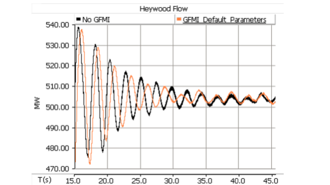
Figure 10 - Comparison of Heywood interconnector performance with un-tuned (OEM default settings) GFM BESS VSG control system
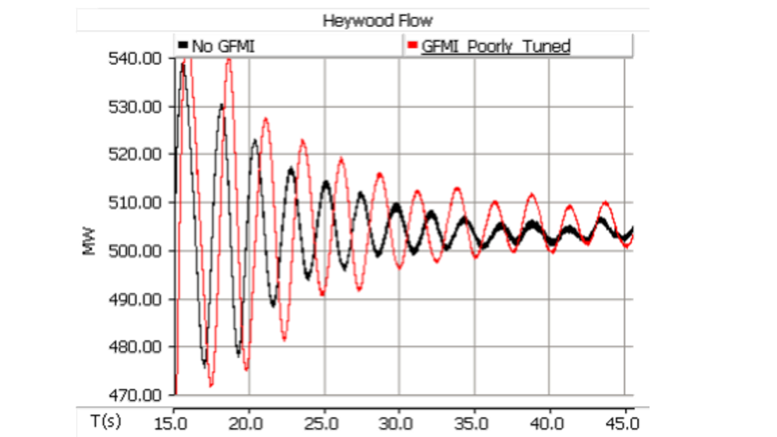
Figure 11 - Comparison of Heywood interconnector performance with improperly tuned GFM BESS VSG control system
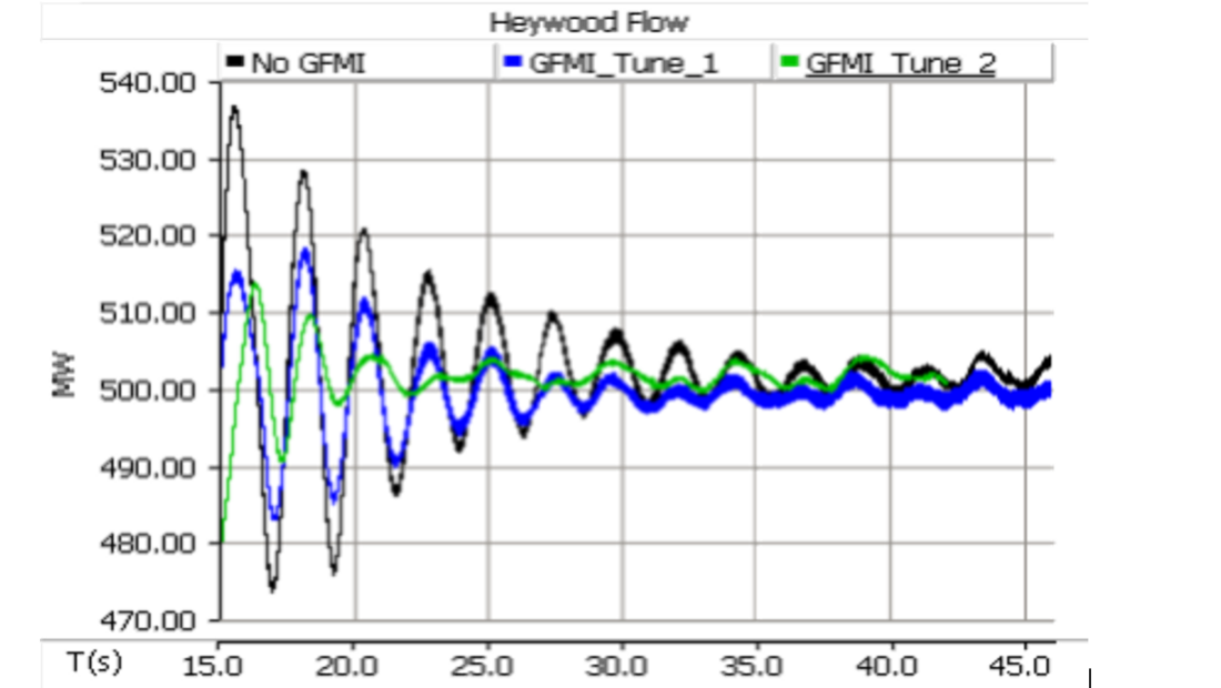
Figure 12 - Comparison of Heywood interconnector performance with different GFM BESS VSG inertia properties
5. Future work
Since the frequency of the mode is 0.5Hz, then the adverse interaction between the IBR and the oscillatory mode is capturable by RMS/Positive sequence simulation tools which are less computationally demanding. Therefore, as part of future, the authors intend to recreate this analysis in the available RMS/Positive sequence tool at AEMO and benchmark the results against EMT results.
6. Conclusion
The results of an oscillatory stability investigation concerned with the integration of large-scale IBRs on a critical interconnector are presented. The investigation has shown that at the present level of synchronous machine and IBR connections, the transmission system is susceptible to oscillatory instability which spans NEM wide. This paper discussed the risk of oscillatory instability coupling between electrical controls of the IBRs with electromechanical interarea oscillations across the power system. With large-scale increase penetration of IBRs and reduction of inertia provision from conventional synchronous generators, Australian power system is expected to be exposed to greater engineering and analysis complexity. Through two case studies, the paper emphasized:
- The importance of appropriate tunning of the IBRs control properties to avoid degradation of any of the network’s oscillatory modes. It is therefore important to promote grid access and design requirements for parts of the system where susceptible to oscillatory instability.
- Both GFL and GFM technologies are required to appropriately tune the relevant control system to avoid introducing any adverse impact on the grid oscillatory modes.
- Operating changes including new thinking and understanding of IBR control system attenuation characteristics at scale are required.
- Accurate plant-level frequency domain models are critically required to support engineering design and analysis.
The findings in this paper are critically important in the Australian power system context to enable a smooth transition from centralized and conventional synchronous generators towards predominantly powered by inverter-based plants.
References
- AEMO, “Power System Limitations in North Western Victoria and South Western New South Wales,” 2019. Accessed: Sep. 07, 2020. [Online]
- AEMC, “National Electricity Amendment (Efficient management of system strength on the power system) Rule 2021 No. 11,” 2021. Accessed: Aug. 17, 2022. [Online].
- J. Quintero, V. Vittal, G. T. Heydt, and H. Zhang, “The Impact of Increased Penetration of Converter Control-Based Generators on Power System Modes of Oscillation,” IEEE Transactions on Power Systems, vol. 29, no. 5, pp. 2248–2256, Sep. 2014, doi: 10.1109/TPWRS.2014.2303293.
- NERC, “Short-Circuit Modeling and System Strength (White Paper),” Atlanta, Feb. 2018. Accessed: Sep. 02, 2022. [Online].
- J. W. Shim, G. Verbic, and K. Hur, “Stochastic Eigen-Analysis of Electric Power System With High Renewable Penetration: Impact of Changing Inertia on Oscillatory Modes,” IEEE Transactions on Power Systems, vol. 35, no. 6, pp. 4655–4665, Nov. 2020, doi: 10.1109/TPWRS.2020.3000577.
- M. Saadatmand, G. B. Gharehpetian, A. Moghassemi, J. M. Guerrero, P. Siano, and H. H. Alhelou, “Damping of Low-Frequency Oscillations in Power Systems by Large-Scale PV Farms: A Comprehensive Review of Control Methods,” IEEE Access, vol. 9, pp. 72183–72206, 2021, doi: 10.1109/ACCESS.2021.3078570.
- AEMO, “Victoria – South Australia (Heywood) Interconnector Upgrade,” 2015. Accessed: Aug. 17, 2022. [Online].
- Badrzadeh B et al., “The Need for Enhanced Power System Modelling Techniques and Simulation Tools,” CIGRE Science & Engineering, vol. 17, no. November, pp. 30–46, 2020.
- N. Hatziargyriou et al., “Definition and Classification of Power System Stability - Revisited & Extended,” IEEE Transactions on Power Systems, vol. 36, no. 4, pp. 3271–3281, Jul. 2021, doi: 10.1109/TPWRS.2020.3041774.
- A. Jalali, B. Badrzadeh, J. Lu, N. Modi, and M. Gordon, “System Strength Challenges and Solutions Developed for a Remote Area of Australian Power System with High Penetration of Inverter-Based Resources,” CIGRE Science & Engineering, vol. 20, Feb. 2021.
- J. Leung, T. George, and S. H. Goh, “Small signal sensitivity technique for determining inter-connector transfer limits,” in 2015 IEEE PES Asia-Pacific Power and Energy Engineering Conference (APPEEC), Nov. 2015, pp. 1–5. doi: 10.1109/APPEEC.2015.7381049.
- H. Liu, L. Jin, D. Le, and A. A. Chowdhury, “Impact of high penetration of solar photovoltaic generation on power system small signal stability,” in 2010 International Conference on Power System Technology, Oct. 2010, pp. 1–7. doi: 10.1109/POWERCON.2010.5666627.
- R. Shah, N. Mithulananthan, and K. Y. Lee, “Large-Scale PV Plant With a Robust Controller Considering Power Oscillation Damping,” IEEE Transactions on Energy Conversion, vol. 28, no. 1, pp. 106–116, Mar. 2013, doi: 10.1109/TEC.2012.2230328.
- M. Ghafouri, U. Karaagac, I. Kocar, Z. Xu, and E. Farantatos, “Analysis and Mitigation of the Communication Delay Impacts on Wind Farm Central SSI Damping Controller,” IEEE Access, vol. 9, pp. 105641–105650, 2021, doi: 10.1109/ACCESS.2021.3096331.
- D. Ramasubramanian, “Differentiating between plant level and inverter level voltage control to bring about operation of 100% inverter based resource grids,” Electric Power Systems Research, vol. 205, Apr. 2022, doi: 10.1016/j.epsr.2021.107739.
- E. W. Kimbark, “How to improve system stability without risking subsynchronous resonance,” IEEE Transactions on Power Apparatus and Systems, vol. 96, no. 5, pp. 1608–1619, Sep. 1977, doi: 10.1109/T-PAS.1977.32490.
- L. Angquist, B. Lundin, and J. Samuelsson, “Power oscillation damping using controlled reactive power compensation-a comparison between series and shunt approaches,” IEEE Transactions on Power Systems, vol. 8, no. 2, pp. 687–700, May 1993, doi: 10.1109/59.260811.
- R. K. Varma and H. Maleki, “PV Solar System Control as STATCOM (PV-STATCOM) for Power Oscillation Damping,” IEEE Trans Sustain Energy, vol. 10, no. 4, pp. 1793–1803, Oct. 2019, doi: 10.1109/TSTE.2018.2871074.
- T. Lund, H. Wu, H. Soltani, J. G. Nielsen, G. K. Andersen, and X. Wang, “Operating Wind Power Plants under Weak Grid Conditions Considering Voltage Stability Constraints,” IEEE Trans Power Electron, pp. 1–12, 2022, doi: 10.1109/TPEL.2022.3197308.
- U. Agrawal, J. O’Brien, A. Somani, T. Mosier, and J. Dagle, “A Study of the Impact of Reduced Inertia in Power Systems,” in Proceedings of the 53rd Hawaii International Conference on System Sciences (HICSS 2020), Sep. 2020, pp. 3010–3017. doi: 10.24251/HICSS.2020.367.
- P. F. Mayer, M. Gordon, W. Huang, and C. Hardt, “Improving grid strength in a wide‐area transmission system with grid forming inverters,” IET Generation, Transmission & Distribution, May 2022, doi: 10.1049/gtd2.12498.