Development of an optimised Fibre-Optic Sensor for Laboratory and Substation non-invasive Calibration of Current Transformers
Authors
Gabriella CROTTI, Palma Sara LETIZIA - INRIM, Italy
Alf-Peter ELG, Mikael LINDGREN - RISE, Sweden
Guglielmo FRIGO - METAS, Switzerland
Jari HÄLLSTRÖM - VTT, Finland
Paolo MAZZA - RSE, Italy
Burak AYHAN, Hüseyin ÇAYCI - TÜBITAK, Türkiye

Summary
Accuracy of voltage and current measurements is a crucial aspect in power systems management, from grid control in high voltage transmission and distribution grids to power quality parameter evaluation, up to energy and metering market fairness. Substation installed instrument transformers are key elements of the high voltage and current measurement chain, so their errors and stability over time should be verified periodically by comparison with metrology grade reference sensors. However, this is a costly and time-consuming procedure, if the instrument transformer in-line verification entails the breaking of the power circuit due to the use of an invasive reference sensor. To face this issue, focused research activities are being developed within the 23IND01 Electrical Energy and Supply Reliability (ENSURE) research project.
In the paper, the ENSURE initial activities are presented, with reference to the development of on-site calibration methods of high voltage substation current transformers (CTs). The focus is on the development of a wideband, non-invasive, all-fibre-optic sensor to be used first as a laboratory reference in the calibration of CTs. Sensor characterisation procedures for use in high voltage substations are also dealt with.
The sensor target performance is 0.05% for the measurement of the current fundamental tone up to at least 1kA and less than 0.5 % up to the 50th/60th harmonic tone.
Starting from a proof-of-concept sensor previously developed, a reference wideband all-fibre-optic current sensor (FOCS) is under finalisation. The features of the FOCS are detailed in the paper and characterisation tests are defined to quantify the current sensor performances under substation realistic conditions. Based on the available documentation, data and experience, a list of influence quantities with their range of variation is identified, focusing on on-site measurement conditions. The analysis is performed considering both the reference FOCS and off-the-shelf non-invasive sensors.
Finally, laboratory characterisation circuits are discussed, which reproduce ideal and realistic substation current sensor operating conditions, along with first examples of characterisation tests.
Keywords
High voltage, electrical substation, fibre-optic sensor, calibration, on-site verification, current transformer, measurement uncertainty, metrology1. Introduction
Accuracy of voltage and current measurements is a crucial aspect in power systems management, from grid control in high voltage (HV) transmission and distribution grids to power quality (PQ) monitoring, up to energy and metering market fairness. Substation instrument transformers (ITs) are key elements of the high voltage and current measurement chains, so their errors should be verified periodically over time by comparison with reference sensors.
The calibration of installed ITs is time-consuming and costing, as it requires the power conductor disconnection, to remove the equipment for the off-line calibration or to insert an invasive reference sensor for live verifications. So, the possibility of carrying out on-site live verifications without de-energisation of the line, making use of non-invasive reference sensors, would save time and reduce costs.
With reference to current measurement, an important aspect is the availability on the market of low power CTs (LPCTs), such as the air-core CTs and the optical sensor based CTs [1][2]. These LPCTs show better characteristics than the conventional ones as to linear dependence on current, wider bandwidth, and reduced weight. Conversely, they may show higher sensitivity to influence quantities and less information is available on their long-term stability [3].
In particular, Fibre-Optic Current Sensors (FOCS) offer immunity to electric interference, compact size, low cost, and a potential to achieve a much higher bandwidth than conventional CTs. So, their use as wideband non-invasive reference sensors for CT calibration is very promising. FOCS enable DC and AC signals measurement, with currents of several hundred kiloampere, relative uncertainty 0.02% [4] and temperature dependence less than 0.002 %/°C, using a sampling rate of a few kS/s. Despite achieving traceable measurement uncertainties < 0,01 %, from 0.1 % to 120 % of a rated current of 10 kA, field conditions remain a challenge where a measurement uncertainty of 0.02 % is needed for calibration of CTs.
FOCS exploit the Faraday effect in a fibre by detecting the magnetic field from a current-carrying conductor. The sensitivity described by the Verdet constant [5] is proportional to 1/λ2, which is why a short wavelength is beneficial. The proposed system uses 650 nm wavelength as opposed to the more commonly used 1300 nm or 1550 nm wavelengths. This however adds complexity and difficulty in obtaining the required components.
Example of calibrations of substation CTs, where off-line measurements are carried out at power frequency by high current generation and reference measurement systems, are reported in [6][7]. Such calibrations are performed over the range of currents required by the IT standards [8] - [11], but they require the power line outage and the disconnection of conductors.
Experiences with live connection of reference non-invasive sensors are limited (see e.g., [12] - [15]). In this case, the current values are imposed by the grid load, then depending on the time and duration of the measurements. The challenges are the availability of a suitable characterised reference sensor for on-site use, its connection in the substation under energised conditions, as well as a realistic estimation of the sensor on-site measurement uncertainty, which has to be sufficiently low e.g., up to one third of the accuracy limits of the CT to be calibrated. The sensor characterisation by comparison with a laboratory standard of higher performances is needed, considering the impact of the on-site circuital conditions and environmental influence quantities. In addition, in case of an installed CT used for PQ measurements, the sensor accuracy should be verified at least in the first harmonic range [8].
To face these open issues, focused research activities are being developed as a part of the 23IND01 Electrical Energy and Supply Reliability (ENSURE) research project [16]. In the paper the initial activities of ENSURE are presented that deal with the study and experimentation of traceable non-invasive current transformer calibration methods for the HV substations. The focus is on the development and characterisation of a new wideband, non-invasive all-optical fibre current sensor. The sensor target performance in the measurement of currents at fundamental tone is 0.05 % up to at least 1 kA and one order of magnitude higher for measurements up to the 50th/60th harmonic tone.
A description of the FOCS under finalisation is provided in Chapter 2. The sensor is to be used first as a laboratory standard. To exploit its features as an on-site reference sensor, in-field measurement conditions and influence quantities are analysed in Chapter 3, also making reference to off-the-shelf non-optical sensors. Laboratory characterisation circuits reproducing both ideal and more realistic substation operating conditions are briefly discussed in Chapter 4 and first examples of characterisation tests on a laboratory developed non-invasive current sensor are presented. Future activities are summarised and conclusions are drawn in Chapter 5.
2. Reference FOCS for current sensors calibration
A new non-invasive FOCS based reference system for on-site substation CT calibrations is developed for live connection by optimising the FOCS sensor from the EMRP ENG61 project [17]. Several challenges need to be tackled for a possible implementation, ensuring target accuracy limits are met, investigating connection methods for the sensor to make connection possible under energised conditions in the substation.
2.1. The FOCS upgrade
The previously developed FOCS [17] has undergone a major redesign. New components, previously not available at the 650 nm design wavelength, have been acquired, including a circulator to better conserve the optical power in the system. A schematic of the system is depicted in Figure 1, based on both the birefringence and polarization modulation principle [18]. Incoherent light is generated by a superluminescent diode operating at 650 nm wavelength.
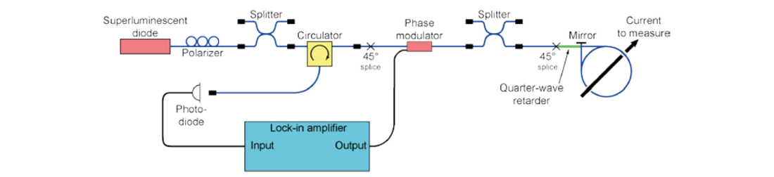
Figure 1 - Schematic of the FOCS. The reflecting mirror is mounted close to the entrance of the sensing coil, adjacent to the quarter-wave retarder for an integer number of turns
A paddle-type polarizer is used to create a linear polarization state. Using a polarization-maintaining splitter, the polarization state can be verified and the stability monitored. The circulator transmits the light towards the first 45° splice, which divides the wave into two linearly polarized orthogonal waves, travelling in a polarisation-maintaining (PM) fibre. A phase modulator is then used to introduce a controlled phase shift between the two polarization states as shown in Figure 2. Ideally, a square-wave is used to bring the system into a state of near-linear response [19]. The modulation frequency is tuned to the travel time through the fibre and sensing coil. The two 99:1 splitters are inserted for monitoring of power and polarization state during preparation and are not used for active operations.
The length of the fibre is coupled to the modulation bandwidth of the phase modulator and also serves to ensure some distance between the electronics and the sensing coil, which is to be placed at potential. The start of the sensing coil is characterized by another 45° splice, immediately followed by a short piece of PM fibre, which is cut at precise length to act as a quarter-wave retarder (changing the orthogonal linear polarization into circular polarization). A mirror is placed at the end of the sensing coil, which reflects the wave and reverses the polarization states. Travelling back through the system, all reciprocal effects are ideally cancelled out. When reaching the circulator, the same polarization state which was injected into the system is sent to the photodiode, whose response is read by the lock-in amplifier.
2.1.1. Closed loop detection
A novel approach to setting up the FOCS uses a different modulation approach [19]. By using ±π/2 square-wave modulation according to Figure 2, the unbalance and its direction can be detected, and the feedback signal generated. The modulation frequency is tuned to the fibre coil eigenfrequency.
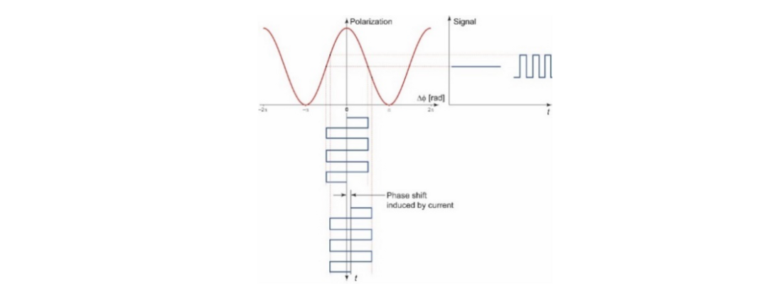
Figure 2 - Square-wave modulation gives near-linear response
2.1.2. Fibre development
Fibres for current sensors are manufactured using either standard low birefringence (LoBi) or high birefringence (HiBi) configuration. The birefringence is used to preserve the polarisation state and counter depolarisation and unwanted polarisation changes when bending the fibre. LoBi fibre can be used down to 250 – 320 mm bending radius depending on the cladding diameter (typically 80 or 125 μm) while a HiBi fibre can sustain down to 30 mm bending radius.
To increase FOCS sensitivity, the core of a fibre was adapted to 633-650 nm with an outer diameter of 125 μm for the cladding of the fibre. Further increase of the Verdet constant using doping by TbAl of LoBi fibres has been studied [5]. However, for the application of live connections in substations, an undoped HiBi fibre has been manufactured.
2.1.3. Live connection
An openable clamp with a 300 mm inner diameter with a hollow channel for fibre insertion has been designed to simplify mounting of the fibre in the field. The purpose is to develop a method for live line in-situ calibrations. The active fibre with coatings has a 0.26 mm outer diameter, which is mounted into a 0.9 mm diameter flexible protection tube and in turn is fed into a 4 mm diameter PTFE tube for insertion after closing the clamp on the current conductor in Figure 3.
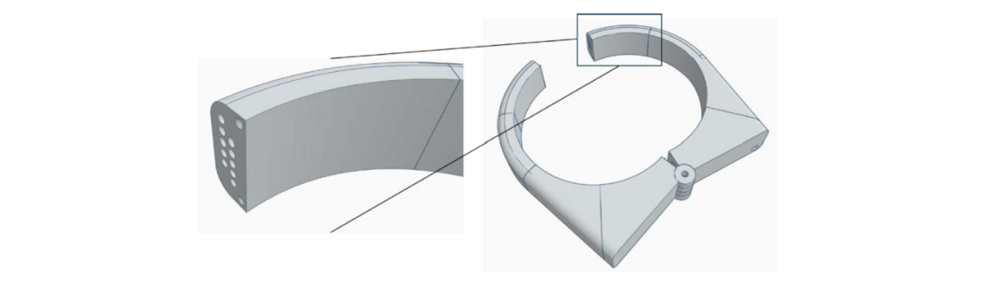
Figure 3 - 3D printed plastic openable clamp with 300-mm inner diameter. The sensing fibre is inserted in the small channels after closure for an integer number of turns
3. Reference sensors characterisation tests
The reference FOCS has to be calibrated to determine its actual transformation ratio (applied primary current to output signal) or ratio error and phase displacement, covering the range of the expected operating currents (from 1 % to 120 % of the maximum rated current of the CTs to be calibrated). Characterisation tests are needed to estimate the effect of the quantities that can influence the measurement result. Relevant corrections and/or uncertainty contributions can then be included in the uncertainty budget associated with the FOCS use (laboratory or on-site use). The preliminary, basic step is the identification of the significant influence quantities and their variation range. The analysis is here carried out making reference to the HV substation site, also considering the impact of influence quantities on non-optic non-invasive sensors (split-core/openable Rogowski coils and CTs).

3.1. Analysis of most significant influence quantities and their assumed variation range
Influence quantities can be classified in 3 groups: i) quantities that depend on the substation operating condition and layout; ii) those related to the sensor realisation or its positioning and iii) environmental quantities. In the first group we can include the power frequency variation and the current distortion (narrow- and wide-band components). As to the variation range, substation CTs are tested in a restricted interval around the rated one (± 1 % for measuring application and 96% to 102 % for the protection one). Frequency variations during 100 % of the time can be higher (for instance, – 6% to +4 % for 47 Hz to 52 Hz) [20]. Since the reference sensor operates with a fixed burden, typically imposed by the reference and CT signal comparator, this quantity is not considered. Further influence quantities are the electric and magnetic fields generated by the adjacent phases, which may combine with the fields produced by nearby high-current busbars, other HV lines or transformers.
As for the second group, deviations from ideal centring of the primary conductor in the sensor aperture are considered. In addition, the sensor tilt with respect to the current conductor axis cannot be disregarded a priori [11]. As to the FOCS, the arrangement of the optical fibre sensor inside a rigid structure (Figure 3), makes its live positioning more stable and repeatable.
As to environmental quantities, most significant contributions can come from ambient temperature, humidity and mechanical stress. Temperature and humidity may vary significantly with respect to the lab, depending on geographical location, season and measurement duration. Values for non-weather-protected locations, as well as live working restrictions [21] and prescription for ITs [8] are here considered for their variation range. Conservative assumptions can be made, based on restrictions for live working (no measurement under rain, snow and high humidity, no chilled wind and condensation conditions, wind velocity < 10 m/s).
Vibrations can be a source of performance degradation. A negligible short-term vibration impact was verified on the metrological behaviour [22] of inductive VTs and the same can be expected for the inductive CTs, but tests on openable devices could be of interest. As to optical sensors, their sensitivity to vibrations can be reduced by suitable implementation solutions.
It’s important to point out that variation ranges are strongly dependent on the HV level, and grid codes and guidelines of the system operator have also to be taken into account.
Main influence quantities and their possible variation range are summarised in Table 1.
| Quantity | Variation Range | Source |
|---|---|---|
| Frequency | 94% to 104% of rated frequency | IEC 61869-1 EN 50160 |
| Distortion level | Total Demand Distortion up to 15% | IEEE 519 |
| Primary conductor position and sensor tilt | See Chapter 4 | IEC 61869-10 |
| Electric and magnetic field from adjacent and nearby phases | Depending on the layout of the HV line | IEC 61869-10 |
| Temperature | -25°C to 55°C | IEC 60721-3-3 |
| Relative Humidity | 5% to 80% | IEC 60721-3-3 |
| Vibrations | 5Hz to 150Hz | IEC 60721-3-3 IEC 60068-2-6 |
4. Set-ups for characterisation tests
4.1. Non-invasive optical current sensor characterisation set-ups
The generation and measurement circuits for the FOCS characterisation are being derived from those experimented in the case of non-invasive non-optical sensors, as described in the next subchapter. The basic circuit is the one in Figure 4, where distance of the return conductor and position of the feeding conductor can be varied. Three-phase current circuits, similar to those experimented in [22] for medium voltage VTs, but rescaled to take into account the HV conductor arrangement, are under development. Experience gained in the set-up of circuits for test under temperature and vibration [22] will be also exploited.
4.2. Non-invasive non-optical current sensors characterisations
The primary current is generated by the inductive transconductance power amplifier and applied to both the current sensor and the laboratory standard current sensor in series. The sensor outputs are compared by the wideband bridge. The ratio error and phase displacement of the current sensor under test are extracted from the synchronized sampled voltage waveforms using the Fast Fourier Transform. A wideband fluxgate current sensor and a wideband current shunt are used as laboratory primary standards with a very small ratio error and phase displacement up to 9 kHz. The wideband bridge is a 24-bit two-channel digitizer with 204.8 kSa/s sampling rate. The laboratory standard current sensor is calibrated by the step-up method based on the multirange compensated current comparator use. Its wideband characterization is based on the sampling ADCs, resistive dividers, current shunts, and ac-dc transfer standards. Ratio error and phase displacement measurements up to 5 kA (max. 10 kA) are traceable to national standards with uncertainties from 0.0005 % (0.0005 crad) to 0.005 % (0.005 crad) in ratio error (phase displacement) measurements and up to 0.05 % (0.05 crad) up to 9 kHz.
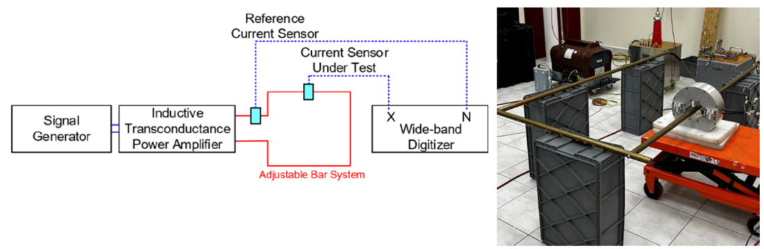
Figure 4 - Schematic representation of the test set-up for non-invasive non-optical current sensors
This comprehensive set-up has been designed for characterising non-optical current sensors considering the deviations from the centring of the primary conductor, and the magnetic field generated by external conductors. As a part of [23], a magnetically shielded openable Rogowski coil was designed and manufactured. In the ENSURE project preliminary characterisation tests have been carried on the usability of this coil as a reference non-invasive and non-optical sensor, by making use of the described set-up. To this end, the conductor was moved to eight directions, as shown in Figure 5, until touching the coil. Maximum deviations from the reference value were found less than 0.130 % and 0.078 crad for ratio error and phase displacement respectively. Worst points (3 and 7) are those close to the opening gaps (Figure 5). A similar exercise was repeated to investigate how the closeness of a return conductor interferes with the measured current. The reference value was assumed when the return conductor was 100 cm far from the coil centre. Maximum deviations from reference value were found to be less than 0.073 % and 0.052 crad for ratio error and phase displacement respectively when the return cable touches to the outer edge of the coil gap.
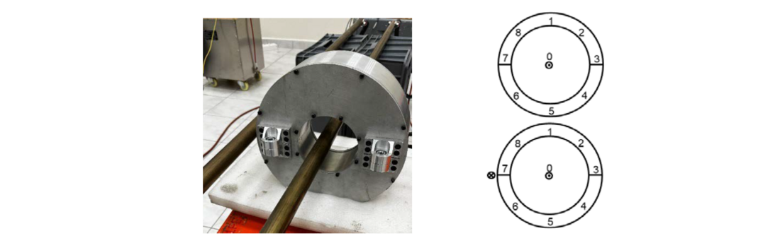
Figure 5 - Test arrangement for investigation of sensitivity to feeding conductor position and sensitivity to return conductor position
5. Conclusions
A new reference FOCS has been presented in the paper. The FOCS is intended for use as a reference sensor in the laboratory calibration of high accuracy CTs. Suitable methods are under study in view of its usage as a wideband non-invasive sensor for live line on-site verification of substation CTs. Characterisation tests that provide a realistic evaluation of the influence quantities impact on the FOCS, as those proposed in the paper, will enable to assess the FOCS on-site accuracy performances and to verify the achievement of the target uncertainties. In this regard, reference generation and measurement set-ups are being developed, extending the field of applicability of those experimented in the characterisation of non-optical non-invasive current sensors. Once the FOCS is characterised, its capabilities in the live line on-site verification of substation CTs will be demonstrated.
Acknowledgment
The project (23IND01 ENSURE) has received funding from the European Partnership on Metrology, co-financed from the European Union’s Horizon Europe Research and Innovation Programme and by the Participating States.
References
- P. Ripka, “Electric current sensors: a review”, Meas. Sci. Technol. 21 (2010) 112001.
- R. da Silva et al., “Optical Current Sensors for High Power Systems: A Review”, Appl. Sci. 2012, 2(3), 602-628; https://doi.org/10.3390/app2030602.
- T.F. Heid, B. Paya, L. Basuyaux, M. Duc Vo, “Accuracy study of a combined low-power instrument transformer in different climatic and pollution conditions”, 48th CIGRE Session 2020, paper A3-224, Paris (France).
- K. Bohnert, P. Gabus, H. Brändle, and P. Guggenbach, “Fibre-optic dc current sensor for the electro-winning industry”, Proc. SPIE 5855, pp. 210-213 (2005).
- D. Istrate, R. Etienne, J. Dubard, et al., "Determination of the Verdet constant of low birefringence single-mode optical fibre", 2016 Conference on Precision Electromagnetic Measurements (CPEM 2016), Ottawa, ON, Canada, 2016, pp. 1-2.
- E.P. Suomalainen and J. K. Hallstrom, "Onsite Calibration of a Current Transformer Using a Rogowski Coil", in IEEE Transactions on Instrumentation and Measurement, vol. 58, no. 4, pp. 1054-1058, April 2009, doi: 10.1109/TIM.2008.2007031.
- F. Rahmatian, P. Mazza, et al., "Accuracy and Calibration of Instrument Transformers with Digital Output”, A3.31 Working Group Report”, ELECTRA N°319 December 2021.
- IEC 61869-1:2023 Instrument transformers - Part 1: General requirements.
- IEC 61869-2:2012 Instrument Transformers - Part 2: Additional requirements for current transformers.
- IEC 60044-8:2002 Instrument transformers - Part 8: Electronic current transformers.
- IEC 61869-10:2017 Instrument transformers: Part 10: Additional requirements for low-power passive current transformers.
- P. Mazza, N. Kuljaca, G. Crotti et al.: "On-site Live Verification of HV Instrument Transformer Accuracy", CIGRE 2006 General Session Parigi, 2006 ref. A3-204.
- P. Mazza et al., "On-site verification and improvement of the accuracy of voltage, current and energy measurements with live-line working methods: New equipment, laboratory and field experience, perspectives", 2014 11th International Conference on Live Maintenance (ICOLIM), Budapest, Hungary, 2014.
- M. Costa, J. C. D. Carvalho, D. B. Dahlke and P. H. M. Santos, "System for high voltage current transformers onsite verification", 2011 IEEE Internat. Workshop on Applied Measurements for Power Systems (AMPS), Aachen, Germany, 2011, pp. 58-61
- U. Kovacevic, V. Milenkovic, N. Kartalovic, et al., "Real time live line high voltage measurement of instrument transformer's ratio and phase displacement errors", 27th International Conference on Electricity Distribution (CIRED 2023), Rome, Italy, 2023.
- A-P. Elg et al., "High-Voltage Metrology for Electric Energy and Supply Reliability", 2024 Conference on Precision Electromagnetic Measurements (CPEM), Denver, CO, USA, M. 2024, pp. 1-2, doi: 10.1109/CPEM61406.2024.10646152.
- A-P. Elg, M. Lindgren, P.O. Hedekvist, S.C. Ebenhag, J. Hällström, D. Istrate, P. Kiiveri, P. Niewczas, G. Fusiek, “Design of a metrology grade fibre optical current sensor”, ISH2017, Buenos Aires, Argentina, 2017.
- G. Frosio and R. Dändliker: “Reciprocal reflection interferometer for a fibre-optic Faraday current sensor", Appl. Opt., vol. 33, no. 25, pp. 6111-6122 (1994).
- H. C. Lefèvre, P. Martin, J. Morisse, et al., “High dynamic range fibre gyro with all-digital signal processing”, Proc. SPIE 1367, pp. 72-80 (1990).
- EN50160 :2010 Voltage characteristics of electricity supplied by public distribution networks.
- IEC 60721-3-3:2019 Classification of environmental conditions – Part 3-4.
- P. Letizia, et al., “Characterization of Instrument Transformers under Realistic Conditions: Impact of Single and Combined Influence Quantities on Their Wideband Behavior”, Sensors 2023, 23(18), 7833; https://doi.org/10.3390/s23187833.
- Hällström J., Ayhan B., Suomalainen E-P., & Valero A., “Rogowski coil with reduced immunity to conductor location and stray magnetic fields”. In R. Díaz (Ed.), 2017 ISH: 20th Intern. Symposium on High Voltage Engineering. Article ISH2017_561.