Integration of Large Power Electronics-Interfaced Loads in Power Systems: Challenges and Opportunities - Part I: Technical Foundations
CIGRE Large Load Joint Task Force C4, C2 & C1
J. MATEVOSYAN - Joint Task Force Lead, ESIG
B. BADRZADEH (Bespoke Energy), E. MEIER (ERCOT), T. KËRÇI (EirGrid), A. ILLICETO (Terna), J. DEANE (SE), Y. SUN (Shell), L. ROBINSON (AEMO), A. BROCHARD (TE-H2)

Summary
This white paper is Part I of a two-part series on the grid impacts and integration challenges associated with the rapid growth of large power-electronic-interfaced loads. Part I establishes the technical foundation by introducing definitions and categories of large loads, highlighting key differences between emerging large loads and traditional industrial loads, and discussing coordination gaps among stakeholders involved in their integration. It then examines major grid impacts, including implications for stability, resource adequacy, and system flexibility, and discusses the need for suitable modeling approaches and grid-facing performance specifications to support reliable integration. Part II addresses issues related to large-load connection processes, as well as operational and planning considerations associated with their increasing deployment. It concludes with a summary of risks / opportunities where additional work, potentially carried out by future CIGRE Working Groups, is required.
1. Introduction and background
Globally, power systems are seeing an increase in large power-electronic-interfaced loads (PEILs). Over the last ~150 years, large industrial demand has typically been motor-driven, supplied directly from the AC grid (no power electronics conversion stage). Power system behavior was primarily shaped by rotating machines, even though sizeable non-rotating loads such as arc furnaces have long existed, and many modern motor-driven processes are now connected via power-electronic interfaces such as variable frequency drives (VFDs). However, recent technological advances mean that many of the largest new loads now being deployed are PEILs. These PEILs, such as data centers, large manufacturing facilities (e.g. semiconductor and battery gigafactories), hydrogen electrolyzer facilities, VFD compressors at liquefied natural gas (LNG) facilities, and large charging stations for electric vehicles (EVs) pose additional or different (compared to traditional loads) risks and considerations to the reliability, security and operability of power systems.
1.1. Definitions of large power electronic-interfaced loads
There is no globally adopted definition for large loads (LLs), or, specifically, for large PEILs. For grid-connected LL facilities, several system operators and network owners have recently proposed or instituted definitions that focus on loads that can have notable impact on the transmission system and are power electronic interfaced; the definitions may also consider both the connection voltage level and maximum power consumption of the load.
Below is a breakdown of some of the existing LL definitions. Rather than listing the definitions verbatim, the focus is placed on minimum size threshold, and/or connection voltage level, facility type and characteristics that various entities state in their LL definitions. Note that while some definitions specifically mention the PEILs, others seem to be applied more broadly to all LLs.
| Entity | MW and kV | Facility Type | Additional Qualifiers |
| Formal Definitions | |||
| Electric Reliability Council of Texas (ERCOT) – USA [1] | ≥ 75 MW | Any facility type with an aggregate peak demand ≥75 MW behind one or more common point of connection (POC) | Certain requirements may only apply to large PEILs, facilities must be at a single site behind one or more common POC |
| Southwest Power Pool (SPP) - USA [2] | ≥10 MW, at 69 kV; ≥ 50MW, > 69 kV | Any facility type | High impact LL (HILL) |
| Fingrid - Finland [3] | Categories of 10-30 MW; 30-250 MW; ≥250MW | Electric boilers and heat pumps, arc and ladle furnaces, data centers, power-to-gas, etc. | Requirements vary depending on the facility type and size |
| EirGrid - Ireland [4] | ≥110 kV | Any facility type | Same requirements for all LL facilities (≥110 kV) |
| Independent Electricity System Operator (IESO) [5] | Any size at ≥ 50 kV and >10 MW at < 50kV | Large computational loads | None |
| Scoping / Emerging Definitions | |||
| North American Electric Reliability Corporation (NERC) [6] | None | Any commercial or industrial facilities | Facilities that can pose Bulk Power System reliability risks |
| Alberta Electric System Operator (AESO) - Canada [7] | Any size, ≥ 69 kV | Data centers | None |
| Australian Energy Market Commission (AEMC), draft rule following AEMO review [8] | Proposed 30 MW threshold for large inverter-based loads | Large inverter-based loads | Draft rule, published 12 March 2026 |
| European Network of Transmission System Operators for Electricity (ENTSO-E) - Europe [9] | None | Industrial sites, data centers, or other major demand centers crucial for balancing the grid | LLs such as data centers, hydrogen electrolyzers, and arc furnaces that directly impact the stability, capacity, and planning of the European transmission grid. |
CIGRE Large Load Joint Task Force (LLJTF) proposes a definition for the purpose of this paper: Large demand facilities that are interfaced with power electronics and have the capacity, either individually or in aggregate, to have material impact on the host grid, across scenario definition, demand forecast, grid connection, grid planning or grid operation phases.
1.2. Definition of partially grid-connected large PEIL facilities
A partially grid-connected PEIL facility refers to an application in which the main power supply is provided by on-site generation, while a minimum grid connection is retained to support auxiliary loads, critical constant-power loads [10], and backup supply requirements.
In case of data center applications, a partial grid connection can imply on-site generation, along with any reactive power compensation, harmonic mitigation, protections and controls required to comply with the grid operator’s technical requirements. A minimum grid connection, typically of several MW, may be retained to support agreed auxiliary and power supply redundancy requirements [11]. In green hydrogen facilities, a partially grid-connected configuration may combine on-site solar and wind generation with multi-GW electrolyzer power-processing units, such as thyristor bridge rectifiers converting AC to DC. The facility may remain grid-connected to continuously supply balance-of-plant loads and other critical 24x7 auxiliary equipment required for safety and continuous operation, see Figure 1. The contracted grid connection capacity need not be equal to the total ampacity of all internal electrical components. In some cases, the allocated grid capacity may be set at the minimum level required to maintain compliance with applicable stability and harmonic performance requirements.
Currently, such partially grid-connected combinations of generation and load do not fit neatly within the existing generation, load, or battery energy storage system (BESS) categories used in connection processes, energy management systems, and market systems.
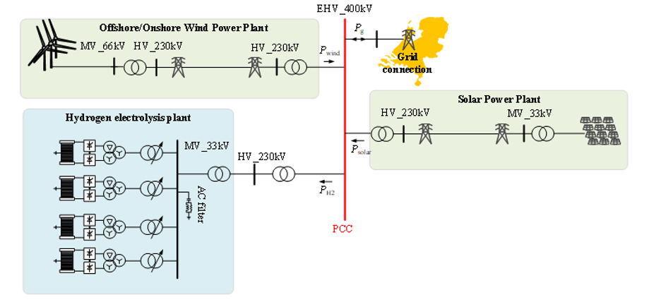
Figure 1 - example of partially grid-connected green hydrogen electrolysis plant concept [12]
1.3. Large load categories
Many facility types can meet the above definitions of LLs [13]. Figure 2 provides an illustrative example of PEIL categories and possible end-uses that fall under each category.
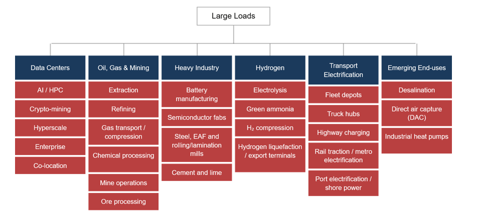
Figure 2 - PEIL categories
This figure focuses on PEILs, since they are the main focus of this LLJTF. Classification is introduced in this paper to illustrate the diversity of PEILs but is not meant to be exhaustive. At present growth in data centers, emerging manufacturing facilities, hydrogen applications and electricity usage in oil and gas facilities are having the largest impact on power systems, although the emergence of other PEILs may have significant impacts in future.
1.3.1. Data center loads
The global data center sector is undergoing significant expansion, with capacity expected to nearly double from 103 GW in 2025 to 200 GW by 2030 [14]. This rapid growth is largely attributable to increased AI adoption, driving demand for higher computational densities and more advanced Graphics Processing Units (GPUs). By 2030 it is estimated that approximately 50% of the total data center workload will be dedicated to AI. While data centers have existed for decades, their scale, growth rate, and geographic concentration are all currently increasing rapidly. Data centers are heterogeneous in design and use, leading to differing impacts on the power system. Facilities may serve a single owner or multiple tenants, often supporting mixed uses such as cloud computing, AI training and inference, and data storage within the same site. These applications have different uptime and latency requirements, resulting in complex variable electricity demand profiles. A data center can potentially change its end-uses throughout its lifecycle. Several types of data centers can qualify as large PEILs:
- Enterprise data centers serve a single customer with relatively uniform computing characteristics.
- Multi-tenant (colocation) data centers host multiple customers and diverse equipment, typically requiring high uptime and low latency, which can limit operational flexibility and increase reliance on backup generation.
- Crypto-mining data centers are highly price-sensitive and exhibit flexible consumption patterns.
- Hyperscale data centers, often serving a single corporate user, can reach several hundred megawatts or more and, despite being fewer in number, have outsized impacts on demand growth and system operations due to their size.
- AI data centers focus on training and inference workloads and typically devote a higher share of total electricity use to computing, with uptime requirements varying by application.
Across all types, data centers share similar core subsystems, but power availability targets, facility and backup design, load profiles, and subsystem energy use can vary significantly.
1.3.2. Oil, gas, and mining
Oil and gas production, transportation, and processing have long been energy-intensive, but recent electrification (to reduce oil and gas asset carbon intensity), such as the adoption of electric drilling rigs, pumps, and motors, has significantly increased electricity consumption of these facilities. Similar trends are occurring in other mining sectors. Because these facilities are large, they now represent an important category of LLs.
The electrification of oil and gas assets is increasingly being driven by the use of large motors controlled by VFDs and/or the use of on-site wind, solar generation and BESS. This increased use of power electronics converters, electric power demand, and remote locations cause oil and gas facilities to face grid connection challenges similar to the loads in other large PEIL categories.
1.3.3. Emerging energy-intensive industries
The industrial manufacturing sector is also undergoing a structural shift, with electricity use in semiconductor and battery manufacturing more than tripling since 2020 and individual facilities often requiring 50–200 MW of continuous power supply. Unlike traditional industrial loads, these emerging facilities are increasingly dominated by power-electronic interfaces, including large rectifier systems, variable-speed drives, DC distribution architectures, uninterruptible power supply (UPS) and battery-buffered systems. These components introduce fast, control-driven dynamics and can significantly alter a facility’s electrical behavior during grid disturbances, including fault response, post-fault active power recovery (PFAPR) characteristics, and interactions with system voltage and frequency.
In the United States, such projects are disproportionately located in states such as Texas, Arizona, and New York and are frequently clustered within small geographic areas, amplifying localized grid impacts. Similar trends are emerging in Europe, where battery gigafactories, semiconductor manufacturing facilities, and electrified steel and chemical plants are being developed in industrial hubs, creating regionally concentrated demand growth and new challenges for transmission planning and generation resource adequacy.
1.3.4. Green hydrogen production
Green hydrogen production via electrolysis is emerging as a major new electricity consumer in Europe, North Africa, Middle East and elsewhere, driven by decarbonization policies. European strategies and project pipelines envision tens of gigawatts of electrolyzer capacity by the 2030s, implying on the order of 100+ TWh of additional annual electricity demand, comparable to today’s data center consumption. While numerous projects have been announced, many remain contingent on market design, network access, and subsidy frameworks. As a result, green hydrogen demand is not yet consistently reflected in transmission and resource planning. In the United States, similar scale has been discussed but project realization and planning remain uncertain and regionally uneven (e.g., Texas and New York).
1.3.5. Mega charging stations for electric vehicles
While data centers and oil and gas are driving much of today’s near-term load growth, electrification of transportation and buildings is expected to be a major longer-term driver, particularly in Europe and, increasingly, Australia [15] where policy frameworks and market incentives are accelerating adoption. Light-duty EVs and electric space heating could be transformative and have distinct system impacts (e.g. managed charging opportunities and winter peak risks in Europe, evening peak amplification in Australia), but these loads largely resemble traditional residential and commercial demand and are not the focus of the LLJTF. By contrast, heavy-duty electric trucks, bus fleets, and logistics depots are more likely to emerge as large PEILs, as centralized charging hubs can require multi-megawatt infrastructure and may connect at the transmission or high-voltage distribution level. High-power, public fast-charging corridors can also approach large scale, especially along freight routes. These fleet and depot loads are growing more rapidly in parts of Europe and Australia, while in the United States they remain more localized, with early deployments concentrated in selected markets such as California.
1.4. How are emerging LLs different from traditional ones?
Compared with historical LLs, many emerging LL facilities are primarily power-electronic-interfaced and exhibit the following high-level characteristics that distinguish them from traditional LLs:
- Size: large in size, from several MW to over 1 GW.
- Geographic concentration: clustered within close geographical proximity due to some attractive conditions such as concentration of end-user, speed of connection process, fiber network (e.g. for data centers and crypto mining facilities), land, water, transmission capacity availability, etc.
- Diversity in design and load make-up: even for the same end-use case, the design of each large PEIL facility may differ in terms of load composition (e.g. compute load vs auxiliary loads in a data center); different technology maturity stages can be housed within the same PEIL facility.
- Sensitivity to grid disturbances: PEILs can exhibit reduced tolerance to voltage and frequency deviations, with some facilities prone to rapid demand reductions, disconnections, or control-driven responses during disturbances (e.g., faults, voltage dips, or frequency excursions), potentially introducing fast, non-linear system impacts.
- Highly variable demand profile: depending on end-use (e.g. data centers or EV mega charging stations) PEILs can have variable and unpredictable demand profile, with rapid, periodic peaks and troughs, and rapid drop-offs and pick-ups of demand.
- Uncertain flexibility: depending on the end purpose of the facility, the available demand flexibility can vary; even if capability for flexible operation is technically possible, it may not fit the business case of a large PEIL facility.
- Rapid and uncertain growth: Application volumes and realized demand can differ materially from early forecasts, creating uncertainty in demand forecasts, adequacy assessments, and network planning.
Diving deeper into emerging PEIL design diversity, there are differences in power-converter capabilities, disturbance ride-through and buffering arrangements (for example UPS, DC-link energy storage, or process buffering), and control, protection, and specification choices that define how those capabilities are deployed. These factors determine how PEIL facilities appear to the power system during normal operation and during grid disturbances. More nuanced technical specifics of large PEILs are discussed in the following subsections.
1.4.1. Differences in power electronic converter capabilities
Line-commutated converter (LCC) (including diode rectifier) and self-commutated converter represent two distinctive power electronics interfaces for PEIL applications. The line-commutated converters are mostly mature with industrial applications such as large motor drive grid interface and classical high-voltage direct current (HVDC) applications. A diode rectifier is also a basic LCC with the firing angle effectively equal to zero and having no DC voltage regulation capability. Because LCCs rely on the AC system for commutation, their fundamental input current is typically lagging, so they draw reactive power from the grid. They also inject characteristic harmonics, for example 5th and 7th harmonics for a 6-pulse bridge. Therefore, LCC installations typically require significant reactive power compensation and harmonic filtering, noting that 12-pulse transformer phase shifting cancels the 5th and 7th harmonics and leaves the 11th and 13th harmonics dominant.
In general, LCCs are commonly used in high-power, steady industrial processes where efficiency, simplicity, and cost are the primary considerations, and some power quality support can be provided locally. Examples include large motor drives (e.g., pumps, compressors), electrochemical processes (e.g., aluminum smelting, chlor-alkali), and certain types of electrolysis systems. Diode rectifier front ends are also widely used in applications where DC conversion is needed but dynamic controllability is not critical. Self-commutated converters (voltage source converters (VSCs)) can control active and reactive current largely independently because commutation is commanded by the devices, not by the AC system. Harmonic emission is mainly set by the converter topology and switching strategy, with pulse width modulation (PWM) pushing dominant components to higher frequencies (kHz range) that are then attenuated by line reactors and filters. Multi-level topologies reduce voltage step size, which generally improves harmonic performance, but compliance at the POC still depends on the converter and filter design.
VSCs are more prevalent in applications requiring fast control, tighter voltage/frequency tolerance, or flexible operation, such as modern data centers (especially UPS systems), EV fast-charging infrastructure, battery-coupled loads, and increasingly hydrogen electrolysis facilities (provided that device reliability and ratings are comparable to LCCs). These applications benefit from independent active/reactive power control, faster dynamic response, albeit with greater design complexity and variability across implementations. VSCs offer strong steady-state controllability, but their disturbance behavior can be highly implementation-dependent across original equipment manufacturers (OEMs) due to differences in topology, controls, protections, and modulation; these details are often not fully visible in network studies unless OEM-specific models are used. LCCs are typically more predictable dynamically due to limited control bandwidth and long operating history, but they have inherent limitations during disturbances, most notably susceptibility to commutation failure during voltage depressions, along with significant reactive power demand and characteristic harmonic emission.
Many modern PEIL facilities are hybrids, combining different converter types across subsystems (for example, a data center with diode rectifier front-end supplies upstream of inverter-based UPS systems), so the net grid-facing behavior depends on the aggregate design rather than a single technology choice.
These differing characteristics of LLCs and VSCs require careful behind-the-meter design to ensure that a PEIL facility can meet the grid operator’s technical performance requirements at POC and deliver robust facility-level behavior during verification and operation.
1.4.2. Differences in process load
1.4.2.1. Challenges associated with AI workloads
Data centers represent a substantial portion of power plant and transformer utilization in areas with high data center concentration. Historically, the aggregation of many services and IT activities within a data center campus could smooth the net facility demand at the grid interface. However, training large-scale AI models requires thousands of GPUs functioning simultaneously, performing identical computations on varied datasets (Figure 3).
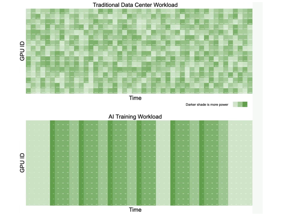
Figure 3 - Traditional data center workload and typical AI training load profile [16]
This operational synchronization induces abrupt transitions between low- and high-power states, resulting in rapid fluctuations in power demand (as illustrated in Figure 3), with step changes up to ~126% relative to the pre-step facility demand when standing loads are included and presenting unique challenges for grid operation (Figure 4):
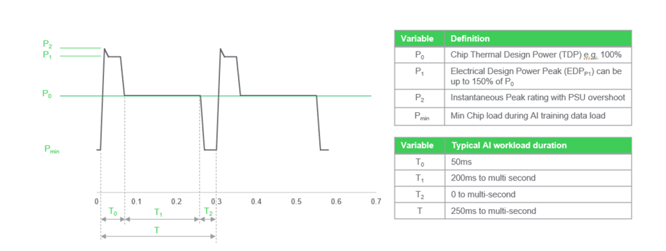
Figure 4 - Typical GPU load modulation in the short term [17]
- Sudden increases in power consumption can outpace the physical ramp rates of available generation resources and operating reserves.
- Repeated transients may increase duty on infrastructure components at the POC; separately, harmonic or control interactions can increase resonance risk where filtering and network impedance are not well matched.
- Sharp reductions in demand can leave energy production systems with surplus energy and limited disposal options.
- Building on the load modulation behavior of GPUs discussed in Figure 4, some vendors are actively addressing this challenge by introducing capacitance at the load and implementing GPU burn‑in drivers to smooth and average the demand profile, as illustrated in Figure 5.
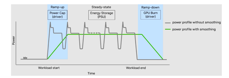
Figure 5 - Typical GPU load modulation with power smoothing [18]
1.4.2.2. Challenges associated with electrolyzer and oil and gas processing loads
Electrolyzer and large oil and gas processing facilities are process-centric with utilities treated as continuous inputs (e.g. heat, water, and electricity). Whilst process load typically treats electricity as a critical utility input with little tolerance for energy mismatch (for example it may not be able to withstand a prolonged loss of grid supply without process interruption or shutdown), its tolerance for grid disturbances (including fault ride-through (FRT) and PFAPR behavior) is a grey area unless explicitly specified due to OEM-specific design and process chosen for the site.
Electrolyzer ramp-up and ramp-down power limits are highly OEM-specific, and since power converters store little energy beyond their DC-link, these ramp-up/down limits (often in the order of seconds to minutes, depending on technology and design) will be directly imposed on the power grid interface. For this reason, the assessment of process load should be carried out to first understand whether there is an overlap between process load phenomena and power grid compliance phenomena timeframes, including the sub-second to tens-of-seconds disturbance window and the longer second-to-minutes operational window. If overlap is found, then a case-specific assessment is required to formulate an appropriate electrical equivalent circuit representation of the concerned process load. If no overlap is found for the relevant study timeframe, then an equivalent load model can be used (e.g. a composition of constant power, current and impedance representation). As one example, aluminum smelter loads are sometimes approximated as a constant DC impedance load for certain short stability assessments (for example around a 20-second window), but this simplification should be applied case-by-case, recognizing that some process plants can still exhibit meaningful control and protection responses within that window.
1.4.3. Differences in large PEIL supply topology and redundancy
Data center electrical architectures [19] are commonly described using tier-style availability concepts [20][21], where higher availability targets are achieved through greater redundancy in power supply paths and tighter tolerances to disturbances. These design choices directly shape the grid-facing behavior of a PEIL facility because they determine the extent to which the facility relies on UPS energy storage and standby generation, the conditions under which it transfers away from the grid during voltage or frequency deviations, and the speed and profile of PFAPR. Consequently, two data center facilities of similar MW capacity can present materially different disturbance responses at the POC, ranging from shallow ride-through capability with partial buffering to rapid load shedding or full transfer to internal power supply. For grid studies and performance specifications, it is therefore more useful to characterize the facility in terms of its redundancy and transfer philosophy (for example, ride-through thresholds, transfer logic, and PFAPR capability) rather than tier labels alone.
1.4.4. Increased on-site energy generation and storage capabilities
One characteristic of many new PEILs, especially data centers, is the existence of on-site energy generation in the form of backup power and co-located resources, along with energy storage that is grid scale or at lower levels such as UPSs. Where configured and permitted for grid-interactive operation, these devices introduce the capability for the grid operator to draw upon energy for demand reduction and ancillary services, while also influencing a PEIL facility’s dynamic performance, and behavior during disturbances.
Data centers currently use UPS units to supply short-term backup power to servers and standby generation for facility-level backup power. Emerging high-voltage DC distribution concepts, including 400 V DC and newer 800 V DC proposals for power delivery, can shift AC/DC conversion from individual server power supplies towards rack, row [22], then facility-level conversion moving the interface between the medium-voltage AC network and the DC bus further upstream. In such architectures, short-term ride-through is envisioned to be provided by energy storage connected to the DC bus, while longer-duration backup may still be provided by generators or other on-site resources depending on the site’s power supply availability target and economics. This change in on-site storage architecture requires new modeling and presents new facility-level responses.
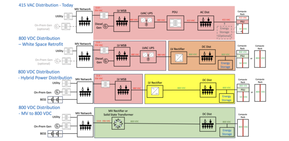
Figure 6 - Data center architecture over time [23]
1.4.5. Large PEIL facility equipment governed by standards not related to grid impacts
PEIL facility equipment such as UPS is originally governed by standards that are not related to grid impacts (i.e. their primary purpose is to ensure high reliability and availability of the facility and to protect internal equipment rather than to support grid performance), increasingly there is a need for UPS designs to additionally consider emerging standards on the grid side. UPS vendors recognize the evolving requirements from the grid side and are proactively pursuing compliance with system operator requirements. When modifications are necessary, careful evaluation is undertaken to determine the viability of updates to existing hardware and firmware. Any changes implemented will maintain the integrity of the UPS's core function: providing stable and uninterrupted power to supported loads.
1.5. Lack of coordination between stakeholders
The integration of large PEILs into the grid is hindered by gaps in coordination and understanding among key stakeholders. These gaps are not only about processes and data, but they are also about different parties using different technical languages and mental models. This leads to misaligned expectations, delays, and suboptimal requirements. While this section uses data centers as the primary example, many of the coordination issues described apply more broadly to large PEILs. Key factors contributing to this coordination gap include:
- No standardized frameworks: Unlike the well-established processes for generator connections, there is no uniform method for conducting connection studies or modeling large PEIL facilities. Each transmission system operator (TSO) or independent system operator (ISO) and region may apply different criteria, and historically the technical standards have focused on generation rather than LLs. Only recently have rules begun to address this gap; for example, grid codes of AEMO, ERCOT, EirGrid, Energinet, ENTSO-E and others are being amended so that plant consuming power, such as data centers, is subject to consistent performance requirements. At present, high-fidelity models and performance requirements for large PEIL facilities are still lacking in many cases, because emerging PEILs do not have the decades of modeling refinement that traditional generators or even inverter-based resources (IBRs) do. This fragmented and unharmonized approach makes it difficult to establish consistent study expectations, slowing project development and increasing the risk of rework.
- Technical vocabulary and framing gaps: Different stakeholders often approach the same issues using different terminology and conceptual frameworks. Data center developers and OEMs typically frame requirements in terms of facility reliability, IT uptime, equipment protection, and site-level power quality, reflecting operational priorities within the facility. In contrast, TSO/ISO engineers are accustomed to integrating conventional generation and IBRs and may have limited familiarity with the technologies and operational practices used in large PEILs, such as UPS operating modes or custom fault-control strategies. Because PEIL facilities employ controls and disturbance responses that differ significantly from traditional industrial loads, misunderstandings can arise. For example, a developer may not understand why the network requires specific FRT behavior, while the system operator may not recognize that, for example, a data center’s backup UPS may need to isolate the facility even during relatively minor grid disturbances. Unlike the renewable generation sector, which has developed a relatively mature and shared technical language over several decades, large PEIL integration is still at an early stage, with limited common understanding across TSOs/ISOs, developers, OEMs, and end users. As a result, study scopes and performance expectations may be mis-specified, for example by implicitly treating a data center as an IBR or as a conventional static load, leading to assumptions that do not accurately reflect actual facility’s technical capabilities and performance.
- Delays and rework in connections: The coordination shortfalls have tangible impacts on project timelines. Differences in modeling assumptions, study methodologies, terminology and milestone expectations often result in each party iterating multiple times to reconcile results and to interpret what the other side ‘really meant’. Connection queues grow as projects undergo rework when early studies are later found to be based on incomplete, inconsistent or mis-interpreted information. This risk is amplified where multiple parties contribute models for different sub-systems (for example facility electrical design, converter controls, and network assumptions) without a consistent end-to-end validation workflow.
- Need for a shared technical language and understanding: Importantly, this coordination gap is not due to a lack of effort or goodwill, it stems from limited mutual visibility into each party’s challenges, requirements and language. Closing this gap will require proactive collaboration across the industry. Joint workshops, information exchanges, and the development of standardized modeling guidelines are now being pursued to build a shared technical language for data center integration. The same approach is required for large PEIL integration more generally, with guidance that distinguishes between technology classes and identifies which behaviors materially affect system performance. By working closely together, stakeholders (ISOs/TSOs, developers and OEMs) can craft fit-for-purpose connection standards, for instance, appropriate FRT and control settings tailored to large electronic loads, rather than copy-pasting IBR standards. This mutual understanding ultimately streamlines the connection process, reducing rework and shortening queues, and ensures that large PEIL facilities can be integrated into the grid securely without imposing unnecessary costs or delays on any party.
2. Grid impacts of PEILs
Large PEILs can affect power system performance across multiple dimensions and timescales, including dynamic performance, resource adequacy, operational flexibility, and reserve requirements. Dynamic performance and stability concerns, such as fast power fluctuations, control interactions, and ride-through behavior, are closely linked to the power-electronic nature of these facilities. By contrast, resource adequacy, transmission capacity needs, ramping, and reserve requirements are driven more by characteristics such as size, geographic concentration, and operational profile. This section addresses the overall grid impacts of large PEILs, and precedes the later discussion of connection processes, planning, and operations, because these cross-cutting issues shape performance requirements, study scopes, and mitigation strategies.

2.1. Stability impacts
Stability refers to the ability of the power system to maintain equilibrium under normal conditions and to recover to an acceptable operating state following disturbances. PEILs can affect power system stability through several mechanisms. Firstly, their sheer size and geographic location and concentration mean that unexpected changes in consumption, e.g. due to internal protection actions, control responses, or process load behavior, can create generation–load imbalances comparable in magnitude to major generation outages. Secondly, their reliance on power-electronic interfaces introduces fast control dynamics that may interact with synchronous machines and other PEILs, potentially leading to cascading events in ways that are not fully captured in planning with traditional load modeling assumptions.
These characteristics have implications across multiple dimensions of stability. During system disturbances, insufficient or poorly coordinated (with power system’s fault clearing and PFAPR strategies) load ride-through behavior can lead to abrupt load loss, delayed PFAPR, or unanticipated reconnection patterns, all of which can stress frequency, voltage, and angular stability margins of the grid. Abrupt loss of demand can create a significant generation-load imbalance and drive rapid frequency and voltage rise (see Figure 7), while delayed or stepwise demand recovery can produce secondary imbalances and steep net-load ramps. At the same time, discontinuous changes in active and reactive power demand can affect post-fault voltage recovery and, in some cases, contribute to local overvoltage or adverse power-flow redistribution. Where multiple large PEILs respond simultaneously, these effects can also alter system angles and stress angular stability margins. Under normal operating conditions, rapid ramps or repetitive power fluctuations from PEILs can challenge real-time balancing, and, in some cases, interact adversely with network and plant controls. Where the PEIL response reinforces (rather than damps) oscillatory behavior, it can reduce effective system damping and excite local- or wider-area oscillatory modes that propagate through the network.
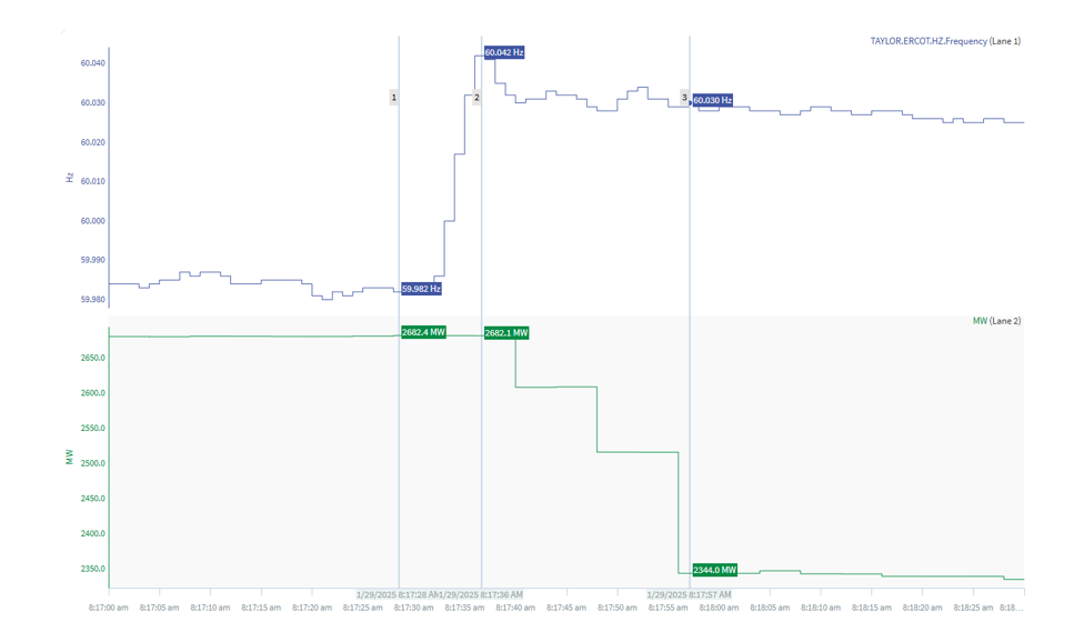
Figure 7 - Example of 300 MW load loss in ERCOT on January 29th, 2025, causing an overfrequency [24]
Experience from recent events (see examples in the following subsections) and studies indicate that many of these risks do not stem from a single failure mode, but rather from the interplay between PEIL behavior, grid operating conditions (including online IBRs), and existing protection and control schemes. Consequently, understanding PEIL impacts on stability requires moving beyond aggregate MW considerations toward a more nuanced assessment of dynamic performance, disturbance response, and control interactions. The following sections therefore examine, in greater detail, two particularly critical aspects of these interactions: PEIL ride-through behavior during grid disturbances, and the potential for oscillatory phenomena driven or amplified by PEIL dynamics.
2.1.1. Lack of disturbance ride-through capability
A recurring phenomenon observed in multiple disturbance events is the partial or full disconnection of PEILs from the grid during normally cleared transmission faults. In these events, PEIL facilities, most notably data centers, cryptocurrency mining facilities, and some oil and gas loads, may cease drawing power from the grid, shed significant MW of demand, or transfer to internal backup supply at relatively shallow voltage depressions. Importantly, this does not necessarily mean that the facility itself trips or ceases operation; in many cases, it continues operating internally while disconnecting from the grid. The transfer of load to backup generation is done to protect sensitive loads within the facility; namely IT load and processes to ensure that the key services they provide to their customers are maintained. While the initiating transmission fault is cleared correctly and within expected timeframes (e.g., 5–6 cycles), the downstream PEILs response (i.e. disconnection from the grid or switching over to its backup supply), if involving several large PEILs, may cause system frequency to increase, potentially triggering overfrequency protection of synchronous generators and leading to cascading generator outages, substantially amplifying the net system disturbance.
For example, ERCOT (Texas, USA) has observed numerous events since 2023 in which single line-to-ground faults triggered tens to hundreds of megawatts of PEIL reductions. Furthermore, in these numerous events, similar voltage dip events have produced widely varying load responses across the same facilities [25].
Another example occurred in Dominion Energy (Virginia, USA) in July 2024, where a lightning-related line fault and subsequent reclosing attempts led to approximately 1,500 MW of data center load transferring to backup generation, driving frequency to 60.047 Hz and requiring emergency voltage mitigation actions [26].
Similar dynamics were observed in multiple events in Ireland’s All-Island Power System. For example, in January 2025 a 220 kV reactor fault near Dublin caused 321 MW of data center load loss, producing a rate of change of frequency (RoCoF) of 0.18 Hz/s in a comparatively small, islanded system [27].
The grid impacts of this lack of voltage ride-through capability are primarily overfrequency and overvoltage risks. The overfrequency risk is higher in systems with a high instantaneous share of PEIL demand, because a larger volume of demand may be reduced or disconnected in response to a single disturbance. The risk is further amplified in low-inertia systems, where there is less ability to arrest the resulting frequency rise. Weak parts of the grid are also at higher risk as a voltage depression due to the initial fault can propagate over larger distance and simultaneously affect (result in trip or backup switch over) of multiple PEILs over a larger geographical footprint, including by causing disconnection from the grid or transfer to internal backup supply. The sudden loss of hundreds of megawatts of demand can cause frequency to rise rapidly and voltages to exceed emergency limits, forcing operators to take corrective actions such as switching out capacitor banks or re-dispatching generation resources.
The ride-through issues occur because PEILs are highly sensitive to voltage dips, and are often governed by proprietary protection logic, UPS transfer schemes (e.g. in data centers), or internal voltage-dip counting algorithms (e.g. in data centers and crypto mining facilities). Unlike traditional industrial loads, their response is fast, discontinuous, and not always coordinated with transmission protection assumptions. As PEIL size and geographic concentration increase, these behaviors shift from being local nuisances to system-wide reliability concerns, especially when multiple facilities respond coherently to the same disturbance.
2.1.2. Low frequency oscillation events
Another major system stability concern is the emergence of forced oscillations, i.e. rapid MW cycling, observed at the grid interface of some large PEIL facilities, most notably certain AI data centers and some crypto-mining facilities, where fast, synchronized, and potentially repetitive load variations can interact with facility controls and the surrounding network. These oscillations can range from sub-second, high-frequency behavior (10–50 Hz) to slower cycling in the 0.1–2.5 Hz range and may persist intermittently or grow in magnitude as load levels increase. In ERCOT, for instance, a large electronic load exhibited oscillations that grew from ~15–20 MW peak-to-peak at lower consumption levels to ~50 MW peak-to-peak at higher loading, with a true oscillation frequency later identified as ~23 Hz using high-resolution disturbance recorder data [28]. A similar event has occurred in the Dominion Energy system, where persistent ~14.7 Hz oscillations were traced to interactions between a data center’s UPS system and grid conditions following nearby hydro unit ramp-downs, revealing an unstable internal mode that became observable only under certain system states [29]. Whether cyclic behavior within the facility is reflected at the grid connection point depends on the electrical architecture and control design of the facility. For example, in double-conversion UPS arrangements, the back-to-back converters and associated energy storage can partially decouple internal load fluctuations from the grid, meaning that internal cycling does not necessarily translate directly into oscillatory behavior seen by the power system.
The grid impact of these oscillations is the potential excitation of normally damped system modes, including subsynchronous torsional modes in synchronous generators or inter-area electromechanical modes, depending on frequency and location [30].
These oscillatory behaviors occur because PEILs increasingly contain complex control systems (e.g., UPSs, AI/ML-driven process controls) that can introduce negative damping or unintentional feedback interactions with the grid. At present, this issue appears to be most relevant to a subset of AI-related data center loads and certain other highly power-electronic, control-intensive applications; it should not be taken as equally characteristic of all data center loads or of PEILs more broadly. However, the underlying mechanism is not unique to data centers and could arise in other PEIL classes where internal controls, buffering arrangements, and grid interactions combine in a similar way. Events observed by AEP (transmission owner in several regions of the United States), including 20 MW cycling at multiple data centers with no clear spectral signature, reinforce that these behaviors may be subtle, load-specific, and difficult to diagnose without close coordination and high-resolution monitoring [31].
2.2. Impacts on flexibility / fast ramping needs
PEILs can materially increase power system flexibility requirements when they exhibit large, non-cyclical ramps in demand, even in the absence of oscillatory or control-driven behavior, discussed above. Step changes associated with process start-ups, batch operations, load transfers, or rapid scaling of computing or industrial activity can occur over seconds to minutes and may reach tens or hundreds of megawatts, creating net-load ramps comparable in magnitude to those of large generating units or variable renewable resources. Accommodating these ramps requires sufficient upward and downward flexibility from generation, storage, or responsive demand to maintain frequency and power balance while respecting transmission and generation units’ operating constraints. In systems with high PEIL penetration or geographic clustering, coincidence ramps across multiple facilities can further compound these requirements. As a result, even when PEILs do not induce stability or oscillatory issues, their ramping behavior can still drive increased needs for fast-responding resources, tighter operational coordination.
2.3. Resource adequacy impacts
Many new PEILs seek to connect quickly and can add demand at scales ranging from hundreds of megawatts to more than 1 GW. Their need for continuous and highly reliable electricity supply means that resource adequacy challenges can emerge rapidly where load growth outpaces the development of generation, storage, or network reinforcements. These challenges are amplified where multiple PEILs are geographically concentrated or where demand ramps materially over time. In some cases, on-site generation or storage may reduce net demand seen by the grid, but its contribution to adequacy depends on its operating mode, duration, fuel availability, and whether it is available during system stress periods.
3. Need for performance specifications for PEILs
Large PEILs may need to meet a small set of grid-facing performance expectations that capture the behaviors that are most material to system security. These typically include: (i) ride-through of voltage and frequency excursions and PFAPR, including the timing and shape of active power restoration; (ii) RoCoF withstand where relevant; (iii) limits on ramping and variability, including both deliberate and automatic load modulation over seconds to minutes; (iv) reactive power and voltage behavior, including the ability to control or constrain reactive current during disturbances and in steady state; and (v) power quality performance, including harmonic emission, flicker, and interaction with network impedance. Where applicable, phase-angle jump withstand can also be specified, particularly for PEILs whose control and protection logic may be sensitive to rapid phase changes during fault clearing and reclosing.
3.1. Performance specifications for PEILs around the world
While each jurisdiction may develop and apply specific performance specifications that meet their system needs, it is desirable to harmonize and standardize these performance specifications as far as practicable. Harmonized requirements lead to increased efficiencies and reduced costs, by creating a level playing field for OEMs and for developers. For instance, in Europe, this is done through ENTSO-E’s Network Codes such as the Network Code on Demand Connection (DCC). While original DCC (2016) did not explicitly differentiate between load types and had static withstand requirements, version 2.0 recently proposed new performance-based specifications specifically for power-to-gas facilities and EVs. Unlike the original DCC, the draft introduces clearer expectations for FRT capability and explicitly recognizes post-fault active power recovery as a system-level stability concern. Each system operator may then apply, subject to regulatory approval, additional or stricter performance specifications (e.g., 1 s PRAPR of demand might work for large, interconnected grids such as the Continental European system but not for small islanded systems such as the All-Island power system of Ireland).
Recently large PEILs performance specifications were published by several system operators and transmission owners around the world, Table 2. While there seem to be no requirements at a distribution system operator (DSO) level yet, it is expected that these will be developed at the distribution level, as the need emerges.
| Org. developing and administering requirements | Function | Country | Draft/Final |
Energinet [32] | TSO | Denmark | Final |
Fingrid [33] | TSO | Finland | Draft |
Tennet [34] | TSO | Germany | Final |
EirGrid [35] | TSO | Ireland | Draft |
RTE [36] | TSO | France | Final |
ERCOT [37] | ISO | USA | Draft |
SPP [38] | ISO | USA | Final |
AESO [39] | ISO | Canada | Final |
IESO [40] | ISO | Canada | Draft |
ATC [41] | Transmission Owner | USA | Final |
Dominion [42] | Transmission Owner | USA | Final |
Southern Company [43] | Transmission Owner | USA | Final |
In Australia, the regulatory position is evolving separately in the National Electricity Market (NEM) and the South West Interconnected System (SWIS). In the NEM, dedicated technical requirements for large inverter-based loads are the subject of an active rule change process at the time of writing this paper. On 12 March 2026, the Australian Energy Market Commission (AEMC) published a draft determination and draft rule as part of its access standards reform package, including proposed provisions for the classification of large inverter-based loads and associated access standards. Until any final rule is made, the existing National Electricity Rules, including Schedule 5.3, remain the applicable framework. In the SWIS, Western Power’s Technical Rules and connection process already require dynamic models to be assessed and validated for relevant connections, and its RMS studies consider disturbance and stability-related performance. However, these requirements do not yet constitute a standalone large-load performance framework equivalent to the dedicated reforms now being developed in the NEM.
In the United States, NERC accelerated efforts to address reliability risks associated with rapidly growing PEILs, initiating a Standard Authorization Request (SAR) to begin developing a framework for oversight of certain LLs. Phase 1 focuses on establishing new terminology (e.g., Computational Load and Computational Load Entity), requiring registration of certain large-load owners/operators with NERC [45], and developing an interim “bridge” reliability standard. Phase 2 is expected to evaluate modifications to existing reliability standards (e.g. modeling and performance standards) to incorporate LL-specific requirements as technical work progresses.
Similarly to the initial IBR performance specifications, there is no harmonization between the LL performance specifications from different regions, and it is rarely clear what criteria or studies the performance specifications are based on, whether ability of PEIL equipment to comply was taken into account, and whether the capability of other grid equipment to operate reliably in presence of PEILs was considered when developing performance specifications for PEILs (e.g. synchronous generator tolerance to low frequency forced oscillations).
3.2. Importance of capturing capabilities and limitations of PEILs in the performance specifications
PEILs should not automatically be assumed to be inferior to IBRs in terms of disturbance tolerance. Figure 8 presents a high-level single-line diagram of the electromagnetic transient (EMT) simulation arrangement used for this study. The model represents a large-scale, commercially used UPS supplying a data center load, based on a user-written EMT model. The arrangement includes the equivalent grid, interface transformer, static bypass switch, rectifier, DC link, inverter, DC/DC converter, battery system, and the downstream IT load. The figure also identifies the point in the equivalent grid where the external disturbances are applied, including the fault and the phase-angle jump. Although the example shown in the simulation results corresponds to a single UPS unit, in practice a hyperscale data center would normally comprise multiple UPS units across several supply blocks. The figure is intended to provide a clearer visual context for the simulation results and to help the reader understand how the imposed grid disturbance propagates through the UPS system to the connected load.
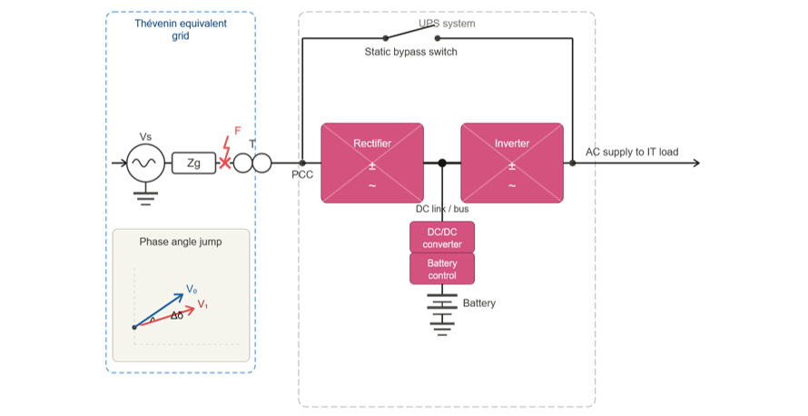
Figure 8 - High-level single-line diagram of the UPS EMT simulation set-up, showing the equivalent grid, transformer, UPS, load, and disturbance location
For example [46], Figure 9 shows voltage, active power, and reactive power at the load and grid sides of a UPS system supplying a data center load for a phase-angle-jump profile of up to ±60 degrees.
The simulation is based on a user-written EMT model developed to represent a large-scale, commercially used UPS topology. The example shown is for a single UPS unit, noting that a hyperscale data center would typically comprise multiple UPS units operating in parallel or across multiple supply blocks. The UPS rides through the full profile without interruption, demonstrating disturbance tolerance that is not always achieved by IBRs under comparable phase-angle jump conditions. In this figure, “PoC” refers to the measurement point at the high-voltage side of the UPS transformer in the simulation model, not the actual data center grid connection point. PoC P and PoC Q, therefore, represent the active and reactive power exchanged between the grid equivalent and the UPS system at this local interface, while Load P represents the active power supplied by the UPS to the IT load.
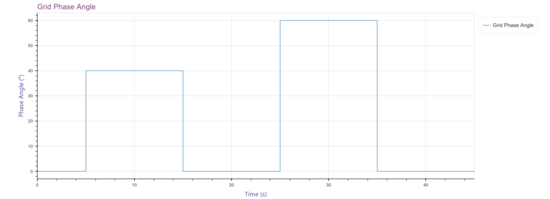
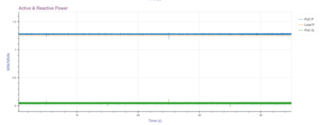
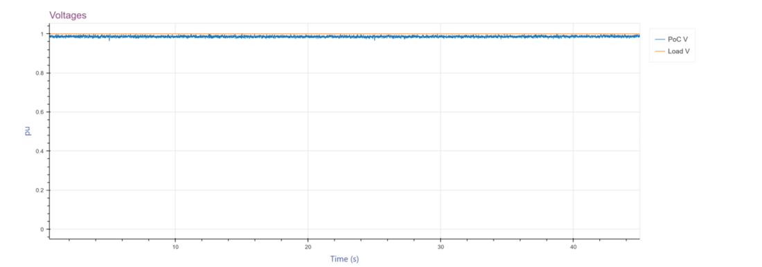
Figure 9 - Voltage, active power, and reactive power at the load and grid sides for an applied phase-angle-jump profile [47]
Some OEMs are actively developing solutions to enhance future product capability, particularly in relation to FRT. Current TSO/ISO proposals typically address both voltage ride-through and frequency ride-through behaviours. The five main requirements are outlined below. Example of possible future voltage ride-through capability for the UPS under consideration is shown in Figure 10.
High and low voltage ride-through (HVRT and LVRT):
Maintaining continuous operation through short-duration faults is increasingly becoming a requirement for large electrical loads, broadly analogous to ride-through expectations for IBRs. The requirement takes shape of a voltage vs time profile for which a PEIL shall stay connected to the grid and maintain power consumption. A temporary reduction in load is acceptable to limit current and avoid tripping upstream overcurrent protection, provided the load remains connected and resumes its pre-disturbance operating point once the grid conditions recover. For example, ERCOT specifies a minimum ride-through time of 150 ms for events where the voltage dips below 0.5 p.u.
HVRT is also defined as the voltage vs time profile for voltage conditions above nominal. The example UPS series (shown in Figure 10) can tolerate a maximum of 1.2 p.u continuously at 400V nominal.
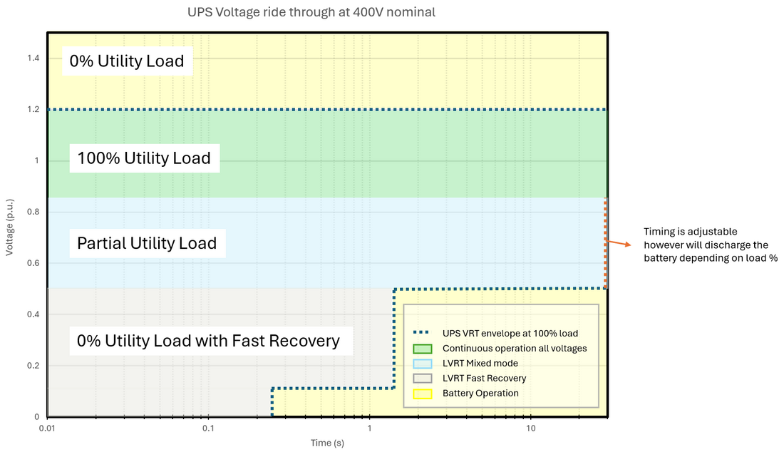
Figure 10 - Future voltage ride-through capability under development of an example UPS [48]
PFAPR:
Large electrical loads are now expected to reconnect rapidly following a brief grid disturbance and recover to its power consumption close to the pre-disturbance value within a defined period of time, which is not how most UPS systems have historically been designed to operate. Traditionally, once a UPS transfers to internal power supply, it remains on battery until the grid is demonstrably stable, then resynchronizes and ramps back gradually. The emerging expectation, however, is that the UPS reconnects to the grid, returns to normal operation, and re-establishes pre-fault conditions within a tightly defined timeframe. One common way to specify this is that, once the grid-side voltage recovers to 0.9 p.u., grid-supplied power must return to at least 90% of pre-disturbance value within a prescribed time, typically ranging from 0.3 s to 5 s depending on the TSO/ISO. Some PEIL designs may be capable of restoring grid-supplied power within sub-second timeframes as per illustrative example in Figure 10, but achievable performance remains product- and implementation-specific and should be demonstrated through validated models and testing.
High and low frequency ride-through:
High and low frequency ride-through requirement is typically defined as the frequency vs time envelope during which a LL is expected to remain connected to the grid and continue power consumption. The UPS’s operational frequency range is typically wider than that stipulated by grid code requirements because it must also operate reliably when supplied by on-site generators. Some PEIL technologies may have intrinsic frequency operating ranges much wider than current grid-code requirements, particularly where they are also designed to operate behind on-site generation. However, compliance should be assessed against the applicable jurisdictional requirements rather than inferred from nominal equipment capability.
RoCoF withstand:
RoCoF withstand requirement is typically defined as specific Hz/s criteria for which a PEIL is expected to remain connected to the grid and continue power consumption. The RoCoF is specified by different TSOs/ISOs which is within the capabilities of the example UPS.
3.3. Other considerations including mandatory vs. negotiated standards, retroactive application to existing sites
Performance requirements for PEILs are still at an early stage of development and, in regions with extensive stakeholder processes, such as those under ENTSO‑E or ERCOT, their approval may take several years. In contrast, many PEIL facilities are developed and constructed in much shorter timeframes; for example, a large data center may be built in as little as 18 months. As a result, a significant number of PEIL facilities are already connected or connecting to the grid in the absence of defined performance requirements. As new requirements are developed and adopted, an important question emerges regarding whether—and to what extent—these specifications should apply to existing facilities that were interconnected before such requirements were established.
While applying new performance standards to existing large PEILs may present compliance challenges, several mitigation approaches are possible. These may include permanent derogations for facilities that cannot reasonably comply, as well as phased implementation for sites that could meet the requirements through software or firmware updates but require time to implement such changes (i.e., temporary derogations). In other cases, network operators and facility owners may agree on mitigation measures such as the installation of ancillary equipment, including static VAR compensators (SVCs) or BESS, to enhance ride-through capability and reduce system impacts.
Retroactive application of performance requirements may be particularly relevant in relatively small or islanded power systems, where the capacity of non-compliant PEILs can represent a significant share of total system demand. This situation has been observed, for example, in the EirGrid system in Ireland [49]. Overall, establishing performance requirements for LLs early in the development of these industries is preferable, as it reduces the technical, regulatory, and economic challenges associated with retroactive compliance.
3.4. Risk of copying IBR modeling and performance specifications
Leveraging existing modeling and performance requirements developed for IBRs may provide a useful starting point for large PEILs, but these frameworks require careful adaptation rather than direct one-to-one adoption. From a system operator perspective, aligning key disturbance performance expectations, such as LVRT and HVRT capability, can help maintain system stability. For example, if a transmission fault produces a deep voltage depression, IBRs are required to ride through voltages down to 0% retained voltage, while PEILs trip or reduce demand, a post-fault imbalance between generation and load may occur, requiring rapid operator intervention and potentially complicating system recovery. If both IBRs and PEILs can ride through comparable disturbances, the risk of such imbalances is reduced and generation and demand recover more predictably following fault clearance.
At the same time, important differences between IBRs and PEILs must be recognized. PEILs are not generating resources but customer facilities with distinct operational objectives, protection philosophies, and commercial drivers. Many facilities, particularly data centers, employ highly sensitive protection and backup power systems designed to maintain uninterrupted service, sometimes transferring to internal supply within milliseconds of transmission or distribution disturbances. Applying IBR requirements without appropriate modification could therefore lead to unintended outcomes, including mis-specified study scopes, inappropriate performance expectations, or requirements that conflict with facility protection and safety objectives.
A more appropriate approach is to define PEIL models and performance requirements based on the behaviors that materially affect the power system, while recognizing practical facility constraints and ensuring that the resulting requirements are technically implementable and verifiable.
4. Large PEIL modeling
4.1. Current modeling practices
Historically, modeling of large PEILs in transmission system studies has often relied on simplified representations, such as static constant-PQ load models derived from protection settings data provided by facility owners, for example as inputs to data center special protection schemes. These representations typically capture relay actions and UPS-initiated voltage or frequency protection logic. Another commonly used approach is the composite load model. Both types of models are routinely used in transient stability analysis tools used by system operators. However, in their commonly applied forms, these representations do not adequately capture the dynamic behavior of large PEILs, particularly during system disturbances such as faults. While simplified models may approximate relay actions or UPS-initiated disconnection, they do not represent transient response of the power-electronic interface itself, including fast controls, current limiting, DC-link dynamics etc. These dynamics can materially influence system behavior during and immediately following a disturbance, for example by affecting voltage recovery, fault current contribution, and the timing, magnitude, and coordination of load reduction. In addition, not all disturbances lead to full disconnection; partial ride-through, staged load shedding, or rapid reconnection can occur, all of which depend on the internal controls of the PEIL. As a result, accurately assessing the impact of PEILs on system stability and post-disturbance recovery with simplified models can be challenging.
OEM-specific models for large PEIL facilities can provide significant advantages over generic representations during the grid connection process, as PEILs may include controls and exhibit internal system interactions comparable in complexity to those found in IBRs. Although current PEIL facilities may not provide the same range of grid support functions typically expected from IBRs, this should not be interpreted as a limitation of the underlying technology. Rather, it reflects differing operational objectives and control philosophies, as well as the fact that grid-facing performance requirements for large PEILs have only recently begun to emerge. Meeting new expectations may therefore require time for equipment redesign, validation, and deployment.
4.2. Modeling needs, gaps, recommendations, risks with inadequate modeling
The current general absence of OEM-specific models does not mean they cannot be developed, and defaulting to simplified models that ignore key dynamics risks missing critical behavior. The priority is to develop models that predict the true capabilities and limitations of the equipment, meaning models that are a faithful representation of physical behavior. These capabilities and limitations can then be incorporated into the overall power system models used for planning and operational studies. Two unhelpful extremes should be avoided: first, adopting a model that implies IBR-style functions when the real product is unlikely to provide them; and second, adopting a model that forces transfer to internal supply for any disturbance, whether shallow or severe. Neither is a realistic representation. While OEM-specific models have not been commonly developed for PEILs, some successful experiences exist. For example, detailed OEM-specific EMT modeling of a UPS shows its ability to ride-through shallower disturbances, as shown in Figure 11, while transferring to internal supply (BESS) for larger disturbances, as shown in Figure 12.
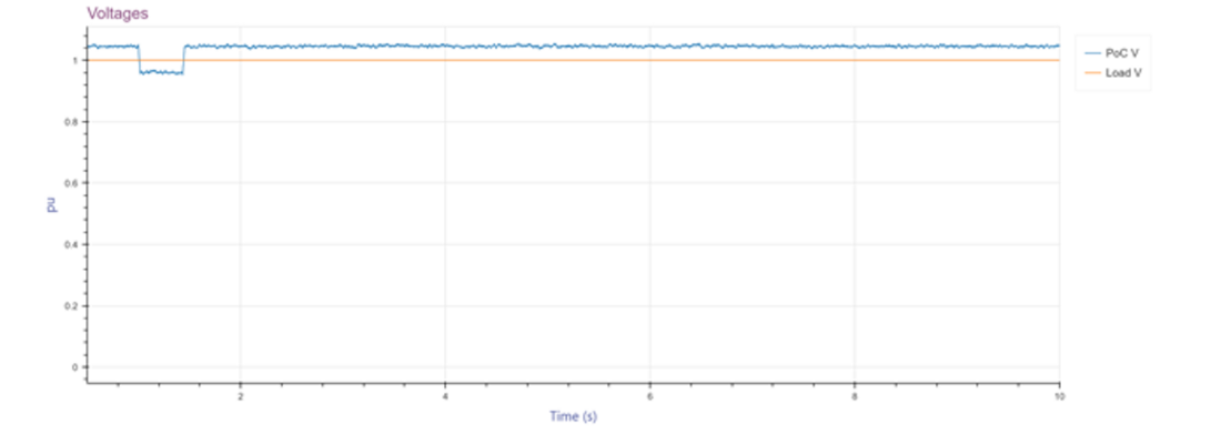
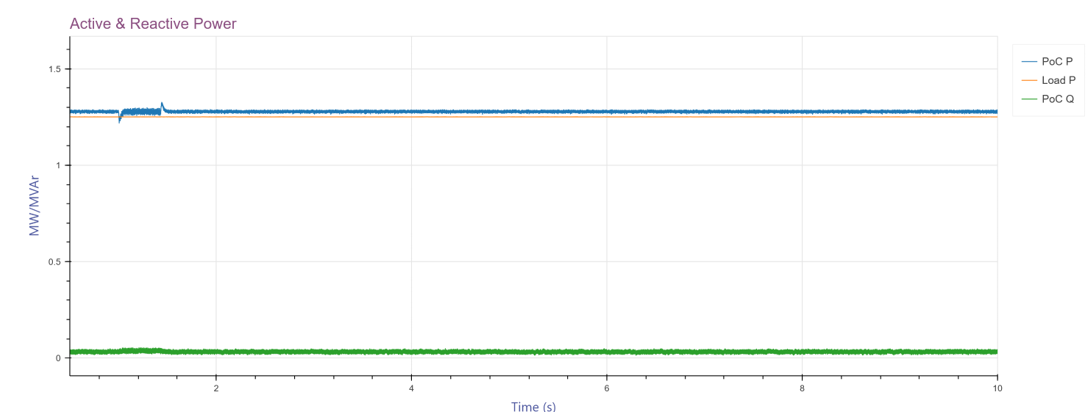
Figure 11 - Voltage, active power, and reactive power at the load and grid side for a shallow fault [50]
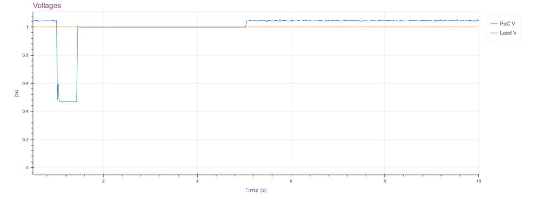
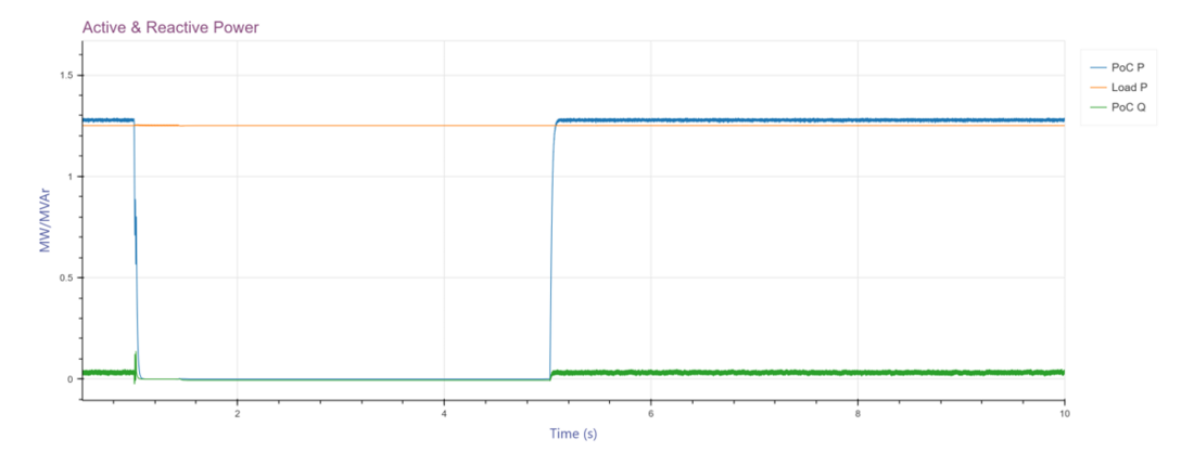
Figure 12 - Voltage, active power and reactive power at the load and grid side for a deep fault [51]
It is also recommended to develop the EMT model first, then derive an appropriate phasor-domain transient (PDT) representation, so that the resulting studies reflect the actual control behavior, including interactions associated with switching frequencies in the tens of kHz. Lack of fit-for-purpose models poses risks to stakeholders in the following key ways:
- System operators may not adequately assess LL performance requirements and system impacts.
- LL operators may sign up to performance requirements that they are unable to meet, leading to compliance and / or operational impacts.
- Other connected parties and / or end consumers may be exposed to negative effects associated with ‘poor’ LL performance or the reliability impact of system events.
A further challenge is that modelling requirements for PEILs are not yet consistently defined across jurisdictions, which limits alignment between OEM model development and system-operator study needs. A more practical way forward is to clarify the modeling requirements in terms of grid-relevant behavior and to support fit-for-purpose representations that achieve sufficient accuracy within reasonable computation times. In that context, both EMT and PDT approaches offer value. EMT can provide higher-fidelity insight into fast converter and protection dynamics when needed, while PDT can be more suitable for broader system studies where scale and turnaround time are critical.
A key modeling gap for large PEILs is the limited ability of existing models to represent the dynamic post-disturbance behavior of PEILs, particularly the automatic recovery of demand following a fault. As discussed above, during severe voltage disturbances, some PEIL facilities may temporarily transfer load to their internal backup systems. This sudden reduction in demand can create a short-term power imbalance and lead to overfrequency conditions. If sufficient downward regulation reserves are not available, system defense mechanisms, such as overfrequency generation tripping schemes applied to IBRs may be activated to restore balance. However, since most current PEIL models do not capture the subsequent automatic recovery of demand once the disturbance clears, system operators may not fully understand the potential sequence of events in which generation is curtailed or tripped in response to the initial load reduction, while demand later returns to pre-disturbance levels, potentially creating a secondary imbalance.
4.3. Need for model validation and verification against installed equipment
Where PEILs models exist, comprehensive model validation should be undertaken routinely, similar to generator model validation, using hardware-in-the-loop testing and/or actual events with high-resolution data.
Whilst plant-level harmonic compliance monitoring and validation can be undertaken periodically, usually annually, plant-level measurements alone rarely allow unambiguous validation of power-electronic load emission models because the observed distortion reflects a combination of primary emissions from the device and secondary effects driven by background distortion and network impedance interactions. Many OEMs can provide device representations such as Norton equivalents, however consistent parameterization and defensible validation evidence remain essential so device contributions can be aggregated and assessed at system level against the system operator’s planning-level emission limits. From a project development perspective, this is compounded by limited early-stage visibility of existing and planned harmonic distortion levels and the grid harmonic impedance, which increases connection and compliance risk and can materially affect project viability.
As the approach to integrating and operating with higher levels of PEILs matures over time, it is anticipated that compliance monitoring will also mature. For example, the AEMC is presently consulting industry on expansion of the NEM compliance monitoring arrangement to encompass additional equipment including PEILs [52].
4.4. Circular dependency between modeling and performance specifications
At present, neither the modeling specifications (data quality and validation methods) nor the performance specifications (FRT, frequency response, ramp rates, etc.) are adequately defined for large PEILs. This creates a feedback loop: without clear performance targets, modeling specifications lack purpose; without robust models, a PEIL facility’s capabilities and limitations cannot be meaningfully tested.
- [1] Based on the existing definition of LL in ERCOT’s Nodal Protocols, Section 2 www.ercot.com/mktrules/nprotocols/current. Additionally, a draft Nodal Protocol Revision Request (NPRR1308) in the stakeholder process proposes a definition of Large Electronic Load (LEL), as a LL in which ≥ 50% of the demand consists of PEIL, such as data centers and cryptocurrency mining facilities www.ercot.com/mktrules/issues/NPRR1308.
- [2] www.spp.org/documents/75954/20260210_revisions%20to%20add%20the%20conditional%20high%20impact%20large%20load%20service_er26-1323-000.pdf
- [3] www.fingrid.fi/en/grid/grid-connection-agreement-phases/grid-code-specifications/draft-for-comments-kjv2026-grid-code-specifications-for-demand-connections/
- [4] www.eirgrid.ie/grid/grid-codes-and-compliance-overview/grid-code-modifications
- [5] ieso.ca/Sector-Participants/Engagement-Initiatives/Engagements/Technical-Requirements-for-Large-Computational-Loads-Connecting-to-the-Ontario-Power-System
- [6] www.nerc.com/globalassets/who-we-are/standing-committees/rstc/whitepaper-characteristics-and-risks-of-emerging-large-loads.pdf
- [7] aesoengage. aeso.ca/49634/widgets/209340/documents/157140
- [8] www.aemc.gov.au/rule-changes/improving-nem-access-standards-package-2
- [9] www.entsoe.eu/2025/12/22/entso-e-position-on-the-need-for-national-connection-requirements-to-ensure-eu-power-system-stability/
- [10] Note in data center terminology these loads are called essential loads, while critical loads refer to compute process load. Technical vocabulary and framing gaps are further discussed in Section 1.4 Lack of Coordination between Stakeholders.
- [11] Note that on-site generation is synchronized with the grid and, if onsite generation is synchronous generation, it will provide inertia and short circuit contribution to the grid.
- [12] “Fault Ride Through Challenges of Co-location Hydrogen Power Plant”, Wind Integration Workshop 2024 Identifier Number 6D_3_WISO24_271_presentation_BeloquiLarumbe_Lucia
- [13] While grid components, such as, for example, a terminal of an HVDC link (when exporting) could also be considered as a PEIL, these are not viewed as PEILs for the purpose of this paper.
- [14] JLL 2026 Global Data Center Outlook, www.jll.com/en-us/insights/market-outlook/data-center-outlook
- [15] Australia is starting from a lower base, and policy support varies by jurisdiction
- [16] developer.nvidia.com/blog/how-new-gb300-nvl72-features-provide-steady-power-for-ai/
- [17] download.schneider-electric.com/files
- [18] developer.nvidia.com/blog/how-new-gb300-nvl72-features-provide-steady-power-for-ai/
- [19] An unfamiliar reader can refer to download.schneider-electric.com/files for details on data center electrical architecture, additional reading is also provided at the end of that white paper.
- [20] constructandcommission.com/data-center-uptime-tiers-explained/
- [21] journal.uptimeinstitute.com/explaining-uptime-institutes-tier-classification-system/
- [22] Row is linear arrangement of server racks positioned side by side.
- [23] nvdam.nvidia.com/assets/share/asset/zlg5snufeo
- [24] Source: ERCOT
- [25] www.esig.energy/reports-briefs/large-load-disturbance-events/
- [26] www.nerc.com/globalassets/our-work/reports/event-reports/incident_review_large_load_loss.pdf
- [27] MPID345-Large-Demand-Facility-Fault-Ride-Through-Issue-and-Proposed-Solutions-EirGrid-and-SONI-Information-Paper-November-2025.pdf.
- [28] www.ercot.com/files/docs/2025/02/28/LL-Oscillation_LFLTF_Mar2025_Final.pptx
- [29] C. Mishra, L. Vanfretti, J. Delaree Jr., T.J. Purcell, K.D. Jones, “Understanding the Inception of 14.7 Hz Oscillations Emerging from a Data Center,” Sustainable Energy, Grids and Networks, 2025
- [30] www.esig.energy/event/lltf-webinar-datacenter-load-impact/
- [31] www.esig.energy/reports-briefs/large-load-disturbance-events/
- [32] en.energinet.dk/media/ep3ofgzp/17_07437-64-dcc-appendix-1dsimulation-model-approved.pdf
- [33] www.fingrid.fi/en/grid/grid-connection-agreement-phases/grid-code-specifications/draft-for-comments-kjv2026-grid-code-specifications-for-demand-connections/
- [34] tennet-drupal.s3.eu-central-1.amazonaws.com/default/2024-04/Anhang_E_Power_to_Gas_Demand_Units.zip
- [35] www.eirgrid.ie/grid/grid-codes-and-compliance-overview/grid-code-modifications
- [36] www. services-rte.com/files/live/sites/services-rte/files/documentsLibrary/Article_8.3.5__CdC_ des_capacites_constructive_d_une_installation_de_consommateurs_1897_f.r
- [37] www.ercot.com/mktrules/issues/NOGRR282
- [38] www.spp.org/documents/74635/spp%20hill%20fault%20ride%20through%20 requirements-v1.0-8-19-2025%20%28updated%20version%29.docx
- [39] aesoengage. aeso.ca/49634/widgets/209340/documents/157140
- [40] ieso.ca/Sector-Participants/Engagement-Initiatives/Engagements/Technical-Requirements-for-Large-Computational-Loads-Connecting-to-the-Ontario-Power-System
- [41] www.atcllc.com/wp-content/uploads/Load-Interconnection-Guide_Rev-15_Final_082225.pdf
- [42] www.dominionenergy.com/-/media/content/large-business-services/pdfs/virginia/facility-interconnection-requirements.pdf
- [43] www.oasis.oati.com/woa/docs/SOCO/SOCOdocs/SOCO_Technical_Requirements_for_TCLLs_-_v1.3_2026-05-01.pdf
- [44] This list is not exhaustive but covers a sample of performance specification documents based on the authors knowledge at the time of writing
- [45] Registration with the North American Electric Reliability Corporation (NERC) means that a registered entity is formally responsible for complying with applicable NERC Reliability Standards
- [46] The example shown in Figure 9 is illustrative only and is included to show that PEIL disturbance tolerance can be materially better than is sometimes assumed; it should not be interpreted as a normative benchmark or as evidence of universal capability across products or facilities
- [47] B. Badrzadeh, Dynamic Modelling of Large Inverter-Based Loads: A Data Centre Perspective, CIGRE Paris Session 2026
- [48] Source: Schneider Electric Galaxy VXL UPS R&D, due to be released in May/June 2026
- [49] MPID345-Large-Demand-Facility-Fault-Ride-Through-Issue-and-Proposed-Solutions-EirGrid-and-SONI-Information-Paper-November-2025.pdf
- [50] Badrzadeh, Dynamic Modelling of Large Inverter-Based Loads: A Data Centre Perspective, CIGRE Paris Session 2026
- [51] B. Badrzadeh, Dynamic Modelling of Large Inverter-Based Loads: A Data Centre Perspective, CIGRE Paris Session 2026
- [52] See https://www.aemc.gov.au/market-reviews-advice/compliance-template-review-2026