Mitigating AC Electromagnetic Interference near Rail Corridors - A Case Study of the Southwest Winnipeg Transmission Improvement Project
Authors
Chen WANG, Emerson ADAJAR - Manitoba Hydro, Canada

Summary
As urban areas grow, the demand for energy and rail transport often leads to shared corridors for railway and transmission line infrastructures. While this approach optimizes land use, it introduces safety concerns due to AC induction. Electrical currents in transmission lines can induce voltages in nearby railway tracks, affecting safe railway operation.
Typically, engineers only recognize AC induction hazards after both infrastructures are built, resulting in costly mitigation efforts. Early identification during the design stage is crucial to avoid expensive changes. However, current methods for analyzing AC interference require advanced simulation tools and reliable field data, which can be hard to obtain without disrupting utility operations.
To address these issues, Manitoba Hydro has developed a guideline for a quick evaluation of induced voltages on rail tracks due to AC interference. This two-step approach begins with a machine learning-based toolbox that helps engineers preliminarily assess whether AC interference might occur between power lines and parallel railways. If needed, a more detailed engineering study follows. The second step involves accurate system modeling and simulations to evaluate AC electromagnetic interference by using the electromagnetic and grounding system simulation software, which allows for precise calculations under steady state and fault conditions.
This guideline enables engineers to determine potential AC interference during the design stage, helping to protect the integrity of railway safety systems and ensure public safety. A case study involving Manitoba Hydro and Canadian National Railway (CNR) on the 115 kV Southwest Winnipeg Improvement project will illustrate this guideline's effectiveness.
Keywords
AC Interference, Machine Learning, Railway, EMI, Safety1. Introduction
Due to population growth in urban areas, the surge in demand for services such as communication, energy, and transportation has placed significant stress on the infrastructure systems providing these essential services. Utilities are challenged to integrate their infrastructures within the congested environments of human societies. Acquiring land for new line routes has proven difficult due to numerous restrictions imposed by private and governmental agencies.
In response, engineers and utility operators from both power and railway sectors collaborated to resolve the issue by devising a plan for corridor sharing, allowing both railway and transmission line infrastructures to share the same physical space. Although this approach seems to be the most practical and efficient way to optimize land use, it introduces new concerns regarding public safety, personnel safety, signal system operation, and the phenomenon of corrosion due to AC induction.
AC induction is an electromagnetic occurrence where a constant change in the electric field can induce current and voltage in nearby conductive materials. The current flow in an AC conductor generates an electromagnetic field that is always perpendicular to the current that produces it. With alternating current, the field expands away from the conductor and then collapses toward it at a rate determined by the system frequency [1]. The strength of the induced current and voltage depends on factors such as the distance from the power source and the magnitude of the current.
In a power line and railway system context, when AC current flows through the transmission line conductors, a time-varying electric and magnetic field is generated around it. Any nearby ungrounded metallic structures, such as railways, that are located close to energized power lines are susceptible to induced voltage and current. This is where most issues between these two types of infrastructure begin, as railway companies use rail tracks for their signaling and communication systems. AC interference that exceeds the allowable operational limits of the railway's electronic systems may lead to unintended or impaired operation, causing equipment issues (such as corrosion, degradation, or malfunction) and personnel safety concerns (like shock hazards) [2-3].
Historical records have documented railway accidents caused by AC interference. For instance, in 1970 in the Netherlands, interference from a high-voltage power line running parallel to a railway caused malfunctions in track signal circuits [4]. Additionally, damage to crossing system circuits was reported during this time [5]. These incidents have made engineers and railway operators more diligent in their designs, particularly when paralleling with other infrastructures.
Organizations such as the AAR, the American Railway Engineering and Maintenance-of-Way Association (AREMA), and the Electric Power Research Institute (EPRI) have published reports addressing the electromagnetic compatibility between railways and power lines [7-8]. The Canadian Standards Association (CSA) standard C22.3 No.3-98 [9] discusses electrical coordination between electric utilities and railway companies in shared corridors and sets safety limits under steady-state conditions. The publication of IEEE Std. 2746-2020 [10] has increased awareness of the importance of AC interference on facilities, including pipelines and railways, though it lacks comprehensive coverage specifically for railways.
Most current research on AC interference between railways and nearby power lines rely on advanced simulation software. These software are typically developed based on either a field approach or a circuit approach. For instance, Reference [11] presents an algorithm to analyze the inductive electromagnetic interference between power lines and nearby non-parallel railway track circuits using the boundary element method. Reference [2] introduces an equivalent circuit model for calculating induced rail currents based on Pollaczek and Carson equations. Reference [12] proposes a method for modeling the railway track using a circuit approach, where the railway electric circuit is treated as an equivalent pi circuit.
Electromagnetic and grounding system simulation software is widely used to examine AC electromagnetic interference. The results from these simulations are heavily dependent on the accuracy of input parameters, which require detailed information on both power lines and railway systems. Unfortunately, field measurements of railway systems are often unavailable since they necessitate interrupting railway operations. Consequently, many assumptions must be made in the existing work, which can lead to significant errors. More so, developing a detailed AC interference model can be costly and time-consuming. This challenge becomes even more pronounced during the transmission line routing phase when only limited information is available.
To address these challenges, we presented a systematic methodology based on the electromagnetic field approach in Reference [13]. This proposed method aids engineers in evaluating AC interference between railways and adjacent power lines with minimal assumptions.
In order to provide a precise and efficient engineering tool for design engineers during the preliminary screening process, we have developed a unique toolbox based on a regression model and machine learning. This tool predicts the induced voltage on rail tracks caused by AC interference from nearby power lines, as discussed in Reference [14].
The main contributions of this paper include:
- Present the Manitoba Hydro two-step guideline for efficiently assessing AC interference issues between transmission lines and adjacent railways.
- Showcase a real project that demonstrates how Manitoba Hydro applied this guideline to determine interference issues between new transmission lines and existing CN rail, along with the proposed mitigation measures.
2. Background
Electromagnetic interference typically involves three types of mechanisms: conductive coupling, capacitive (electric field) coupling, and inductive (magnetic field) coupling. Under steady-state conditions on power lines, only inductive and capacitive coupling are significant, with inductive interference being the dominant factor. In contrast, conductive coupling occurs during fault conditions on power lines when fault currents flow to the ground, causing ground potential rise (GPR) in the affected area.
2.1. Capacitive Coupling
Capacitive coupling, also referred to as electrostatic or AC coupling, occurs when nearby conductors create capacitance, allowing energy transfer through time-varying electric fields. Railway tracks, supported by resistive ballast, can pick up induced voltages from power lines, posing shock hazards despite typically low current levels. Compared to inductive coupling, capacitive coupling generally has less impact on railway signaling and communication systems [15].
2.2. Inductive Coupling
Inductive coupling occurs when a time-varying current flows through a power line, generating a time-varying magnetic field around it. When a power line runs parallel to other nearby conductive pathways, such as a railway, mutual inductive coupling occurs between the systems. Inductive coupling is the primary type of AC interference when a power line runs parallel to a railway track over a considerable distance. The inductive component generally has a greater magnitude and extends farther than the conductive component [16].
In inductive coupling, maximum potential values can be found at the ends or interruptions along either the power line or the railway, such as where power lines are transposed or where the railway diverges from the power lines. When the two systems interact, points of bending or termination create abrupt current discontinuities and rapid changes in the separation between the railway and power lines. This strong discontinuity in electromagnetic fields (EMF) at the endpoints of the railway track can lead to significant leakage currents, resulting in elevated potential levels on the railway tracks [17].
2.3. Conductive Coupling
Conductive coupling typically only occurs under a ground-related fault event. A portion of fault current would flow into the local ground system and transfer to the nearby metallic objects such as the railway track. Unbalanced faults, particularly single-line-to-ground faults, pose the greatest risks to both personnel and equipment.
Therefore, it is crucial to consider conductive interference during fault conditions, as it is vital to ensure the proper operation of railroad facilities. This helps prevent damage to equipment and reduces the risk of injury to personnel due to elevated voltages during power system faults [2].
2.4. Railway Operational and Safety Criteria
When AC interference is a concern for railway systems, it is important to consider two major categories of design limits. The first category encompasses safety limits that apply in both steady-state and fault conditions of power lines. The second category pertains to operational and equipment limits that aim to prevent malfunctions or permanent damage caused by excessive induced voltage or current.
In steady-state conditions, when the railway is situated near power lines, inductive coupling is the primary source of interference. The safety limits for magnetic induction differ among standards due to varying underlying assumptions. A common safety limit in steady-state conditions is set at 50 V rms. This limit assumes a body impedance of 2000 Ω and follows the c1 curve (Figure. 1) currently defined in the IEC Standard. In Canada, C22.3 No. 3 has been adopted by all railway companies. For adjacent track sections of equal length that are separated by insulated joints, the AC voltage across each insulated rail joint can reach twice the maximum voltage of each rail with respect to remote earth. Therefore, to maintain the voltage across insulated rail joints at or below 50 V, the maximum rail-to-remote earth voltage should not exceed 25 V [9].
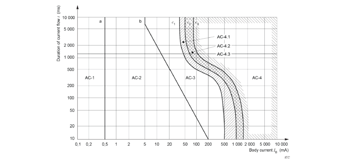
Figure 1 –Zones of Effects of AC Currents (15 Hz To 100 Hz) on Persons for A Current Path Corresponding to Left Hand to Feet [18]
Under fault conditions, the acceptable level of longitudinal induced voltage in railway signaling and communication circuits is 430 V rms, according to CSA [9]. The safety limits for fault conditions are well established in the IEC standard 60479 [18] and IEEE Standard 80 [19]. In North America, IEEE Standard 80 is a commonly recognized guideline adopted by railway companies.
In addition to the safety limit, the AREMA guidelines [20] also establish induced voltage limits for communication and signal equipment. A recommended limit of 5 V rms is advised for motion-sensitive systems at highway grade crossings, while a limit of 10 V rms is set for audio frequency track circuits.
3. Manitoba Hydro Power Line and Railway AC Interference Guideline
Understanding the interaction between power lines and railway systems is crucial due to the potential for AC interference, which affects system reliability and public safety. However, there is a lack of engineering tools and general guidelines for the early identification of AC interference between these two systems. This is immediately needed by utility and railway engineers to ensure the proper design and cooperation of railway and power lines. Early identification of hazards is essential to avoid costly and invasive designs.
To address this issue, Manitoba Hydro collaborated with the University of Saskatchewan to develop an internal guideline for evaluating AC interference between railways and power lines, which minimizes interruptions to utility operations and can be utilized even at the design stage of the construction project. This guideline consists of two steps. The first step involves using an internally developed toolbox based on machine learning algorithms. This tool helps design engineers conduct a preliminary assessment to determine whether AC interference may exist between power lines and nearby parallel railway tracks. This can be considered a quick go/no-go assessment to decide if further investigation is necessary. The second step requires detailed system modeling and engineering studies to evaluate AC electromagnetic interference between railways and adjacent power lines. This section discusses the methodology used for both steps in detail.
3.1. Step 1 – Quick Assessment using Toolbox
Two criteria are used in this step to confirm if AC interference exists between the power line and adjacent railway, which is summarized in Table 1.
| Design Limits | Operation Conditions | Comment |
|---|---|---|
| Rail-to-Rail Voltage Cross Joint <50 V | Steady State Condition | Safety |
| Rail-to-Ground Voltage <25 V | Steady State Condition | Safety |
| Rail-to-Rail Voltage between Two Tracks <10 V | Steady State Condition | Equipment |
| Separation Distance <50 m | Fault Condition | Safety |
The methodology for developing the model and toolbox involves five steps.
Step 1: Simulation Model Development and Data Generation
A group of simulation models has been developed using electromagnetic and grounding system simulation software to generate the necessary dataset for creating data-driven regression models. As discussed in Section 2, inductive coupling is the primary factor influencing interference over capacitive coupling under steady-state conditions. Therefore, the voltage of the transmission line has a minimal impact on the interference between the transmission line and the railway track, which was excluded from consideration.
For the sensitivity study, five inputs were considered. This dataset includes operational current ranging from 500 to 1800 A, soil resistivity varying from 10 to 1000 ohm.meters, ballast resistance from 1 to 100 ohms, rail track lengths from 1000 to 3734 meters, and separation distances from 10 to 200 meters. The output of the model is the ground potential rise on railway tracks resulting from electromagnetic interference caused by adjacent power transmission lines.
The tower geometry is based on a standard Manitoba Hydro 230 kV single-circuit steel lattice tower with a 400-meter span, and the minimum ground clearance is determined according to CSA C22.3 No. 1 standards.
Step 2: Training Regression Algorithms with a General Setting
To identify suitable regression algorithms for the dataset, the algorithms are trained using the default hyperparameter settings in the MATLAB Regression Learner app. The regression algorithms considered in the analysis are listed in Table 2.
| Family of Regression Models | Regression Models |
|---|---|
| Linear Regression | Linear Regression model |
| Interations Regression model | |
| Robust Regression model | |
| Stepwise Linear Regression model | |
| Regression Trees | Medium Tree |
| Coarse Tree | |
| Fine Tree | |
| Support Vector Machines (SVM) | Linear SVM |
| Quadratic SVM | |
| Cubic SVM | |
| Fine Gaussian SVM | |
| Medium Gaussian SVM | |
| Coarse Gaussian SVM | |
| Gaussian Process Regression | Rational Quadratic |
| Squared Exponential | |
| Matern 5/2 | |
| Exponential | |
| Ensemble of Trees | Boosted Trees |
| Bagged Trees | |
| Neural Network (NN) | Narrow NN |
| Medium NN | |
| Wide NN | |
| Bi-layered NN | |
| Tri-layered NN |
Step 3: Selection of Potential Regression Algorithms
Potential regression algorithms are selected by analyzing the quality metrics of the models developed in Step 2. The selected algorithms include Gaussian Process Regression and Neural Network. The quality metrics considered include the R-squared value, Normalized Root Mean Square Error (NRMSE), Mean Square Error (MSE), and Mean Absolute Error (MAE).
Step 4: Hyperparameter Optimization
Bayesian optimization is employed to fine-tune the chosen regression algorithms. Two acquisition functions used in the Bayesian optimizer are "Expected Improvement per Second Plus" and "Probability of Improvement." The best acquisition function is selected based on the quality metrics of the developed models.

Step 5: Performance Analysis
New models are created using the selected regression algorithms with optimized hyperparameters. The optimum regressors for estimating the ground potential rise on rail tracks 1 and 2 are determined based on the quality metrics. If no optimum regressor is found, the maximum number of iterations and the acquisition function of the Bayesian optimizer are adjusted, and the hyperparameters of the potential regression algorithms are further optimized.
Therefore, the induced voltage on each railway track can be estimated using the proposed methodology. For instance, regarding the induced voltage on the rail track that is closer to the power line, it was found that although the "Expected Improvement Per Second Plus" based Gaussian Process Regression (GPR) model and the "Probability of Improvement" based Neural Network (NN) regression model exhibit similar performance on the training dataset, the NN model performs comparatively better on the testing dataset. Therefore, the "Probability of Improvement" based NN model (Table 3) is selected in this toolbox to predict the induced rail-to-ground voltage on the rail track.
| Acquisition Function | Training Results | Testing Results | |||||||
|---|---|---|---|---|---|---|---|---|---|
| RMSE | R-Squared | MSE | MAE | RMSE | R-Squared | MSE | MAE | ||
| Expected Improvment per second plus | Gaussian Process Regressor | 0.7967 | 1 | 0.63473 | 0.29888 | 0.5500 | 1 | 0.30257 | 0.31493 |
| Neural Network Regressor | 3.7675 | 0.96 | 14.194 | 2.5262 | 3.2483 | 0.98 | 10.552 | 2.3651 | |
| Probability of Improvement | Gaussian Process Regressor | 0.88768 | 1 | 0.78798 | 0.43309 | 0.68371 | 1 | 0.46746 | 0.38121 |
| Neural Network Regressor | 0.79629 | 1 | 0.63409 | 0.38417 | 0.53146 | 1 | 0.28245 | 0.34688 | |
The final developed models have been programmed into a standalone toolbox using MATLAB. This toolbox is designed to predict the induced voltage on railway tracks under steady-state conditions. It requires simple input parameters, which include 1) power line current, 2) the separation distance between the railway and power lines, 3) ballast resistance, and 4) the length of the rail track. The user interface of the toolbox is shown in Figure 2.
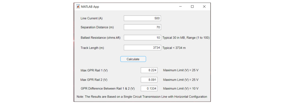
Figure 2 –Toolbox User Interface
3.2. Step 2 – Guideline to Conduct Detailed Engineering Modeling
Due to the complexity of AC electromagnetic interference issues between power lines and railways, commercial electromagnetic and grounding system simulation software is often necessary to simulate the induced voltages on railway systems. Manitoba Hydro collaborated with the railway company to establish a detailed step-by-step procedure for developing an engineering model [13]. Four steps are involved.
Step 1: Conduct field measurements to determine the local soil resistivity.
Step 2: Measure the ballast resistivity in the field and use software to calculate the corresponding ballast resistance.
Step 3: Compute the equivalent coating resistivity based on the calculated ballast resistance from Step 2 and model the railway track as a conductor with the appropriate coating.
Step 4: Create a comprehensive system model that includes both power lines and railways in order to calculate the induced voltages on the railway tracks.
The ballast resistance is a key parameter that represents the insulating properties of railway ballast, and it usually requires direct measurement on the railway track. Therefore, additional safety procedures and coordination with railway operations are essential. To mitigate impacts on railway operations, an indirect measurement method proposed in [13] is adopted by Manitoba Hydro, which involves back-calculating the ballast resistance from a simple ballast resistivity test. This approach has been validated by field measurement and proven to be accurate.
4. Southwest Winnipeg Improvement Project Case Study
The Manitoba Hydro Southwest Winnipeg Transmission Improvement Project involves the reconstruction of several 115 kV transmission lines in the southwestern Winnipeg area to enhance reliability in south and central Winnipeg. This project includes the replacement of numerous existing transmission towers and conductor upgrades in certain sections of the line to prepare for future load growth in the service areas.
The 80-year-old 115 kV transmission lines run along Manitoba Hydro's existing Right-of-Way (ROW), primarily situated in residential neighborhoods. A 900-meter segment of the transmission line is located near and parallel to the Canadian National Railway (CNR) at Mile 2.39 along the Letellier Subdivision within the Winnipeg city limits.
Based on the preliminary assessment, the toolbox confirmed that the induced voltage meets the required criteria under steady-state conditions; however, Ground Potential Rise (GPR) could be an issue due to the small separation distance. Therefore, a detailed engineering study is necessary.
There are six 115 kV circuits operating within this joint corridor alongside the CNR rails, and the transmission line information is detailed in Table 4. The railway data was provided by CNR. Soil resistivity was measured directly using the Wenner method. After reviewing the system configuration, Manitoba Hydro confirmed that the maximum fault current level at the project site will not exceed 16 kA. If this limit is exceeded in the future, Manitoba Hydro plans to use a current-limiting device, such as a Neutral Grounding Resistor (NGR), to keep the fault current within the required limits. A three-phase fault will not result in any ground potential rise, so only single line-to-ground fault conditions are considered, which could pose touch and step voltage hazards. Figure 3 displays the software model, which encompasses both the transmission lines and railway systems.
| Line # | Phase Conductor | Shield Wire | Rulling Span (m) |
|---|---|---|---|
| VS27 | ACSR Cardinal & Type 16 ACSS Grosbeak | 19 # 8 ALumoweld & 9mm EHS | 280 |
| VH1 | ACSR Cardinal & Type 16 ACSS Grosbeak | 19 # 8 ALumoweld & 9mm EHS | 280 |
| XH46 | ACSR Cardinal & Type 16 ACSS Grosbeak | 19 # 8 ALumoweld & 9mm EHS | 280 |
| YS33 | ACSR Cardinal & Type 16 ACSS Grosbeak | 19 # 8 ALumoweld & 9mm EHS | 280 |
| S1 | ACSR Oriole | ACSR Leghorn | 304 |
| S2 | ACSR Oriole | ACSR Leghorn | 304 |
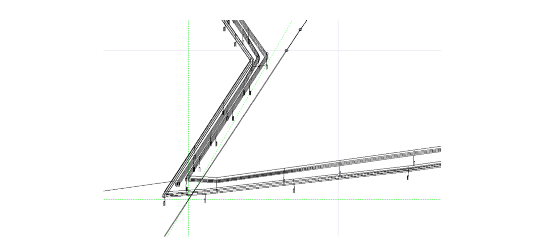
Figure 3 – Detailed Model for Co-location Section
The accuracy of the completed software module model was validated using field measurements. The simulated values are approximately 15-20% larger than the actual values. These differences can be attributed to the line sag value used in the simulation model, which remains unknown because the construction of the transmission lines has not yet been completed or energized. Consequently, the worst-case line sag value was used for the simulation. This indicates that the proposed model is reasonably accurate and conservative for this study as agreed with CNR
According to the toolbox, all induced voltages observed during the steady-state study are within the required safety criteria. This is also confirmed by detailed modeling. As expected, the detailed model indicated that the touch voltage under fault conditions could pose a safety concern that needs to be addressed. The calculated touch voltages are presented in Table 5.
| Case # | Touch Voltage (V) |
|---|---|
| F1A - Summer Condition (fault at the tower at the north end of parallel section) | 383.25 |
| F1A - Winter Condition (fault at the tower at the north end of parallel section) | 1634.79 |
| F1B - Summer Condition (fault at the tower at the south end of parallel section) | 392.50 |
| F1B - Winter Condition (fault at the tower at the south end of parallel section) | 2002.87 |
| F1C – Summer Condition (fault at the middle tower of parallel section) | 359.44 |
| F1C – Winter Condition (fault at the middle tower of parallel section) | 1478.33 |
The touch voltage is connected to the maximum local ground potential rise (GPR). GPR is influenced by the local ground resistance and the amount of fault current that flows into the local ground system. To reduce GPR, it is important to lower the resistance of the local footing. In addition to achieving lower footing resistance, adding extra shielding wire can create more electrical pathways, allowing fault current to flow back to the source more effectively. This increase in the number of paths helps to distribute the fault current, which results in a reduced amount of fault current flowing into the local ground system at the fault location. The proposed mitigation plan included additional bonding in the concrete foundations and bonding all transmission lines together within this corridor as shown in Figure 4. With consideration of the proposed mitigation plan, the GPR of the rail track and touch voltage are within the safety and operational limit as per CNR specifications. The updated results are shown in Table 6.
| Case # | Tuch Voltage (V) | GPR of Rail Track (V) |
|---|---|---|
| F1A - Summer Condition (fault at the tower at the north end of parallel section) | 210.99 | 157.66 |
| F1A - Winter Condition (fault at the tower at the north end of parallel section) | 165.32 | 133.48 |
| F1B - Summer Condition (fault at the tower at the south end of parallel section) | 194.53 | 131.62 |
| F1B - Winter Condition (fault at the tower at the south end of parallel section) | 151.55 | 108.50 |
| F1C – Summer Condition (fault at the middle tower of parallel section) | 203.93 | 151.45 |
| F1C – Winter Condition (fault at the middle tower of parallel section) | 161.01 | 127.05 |
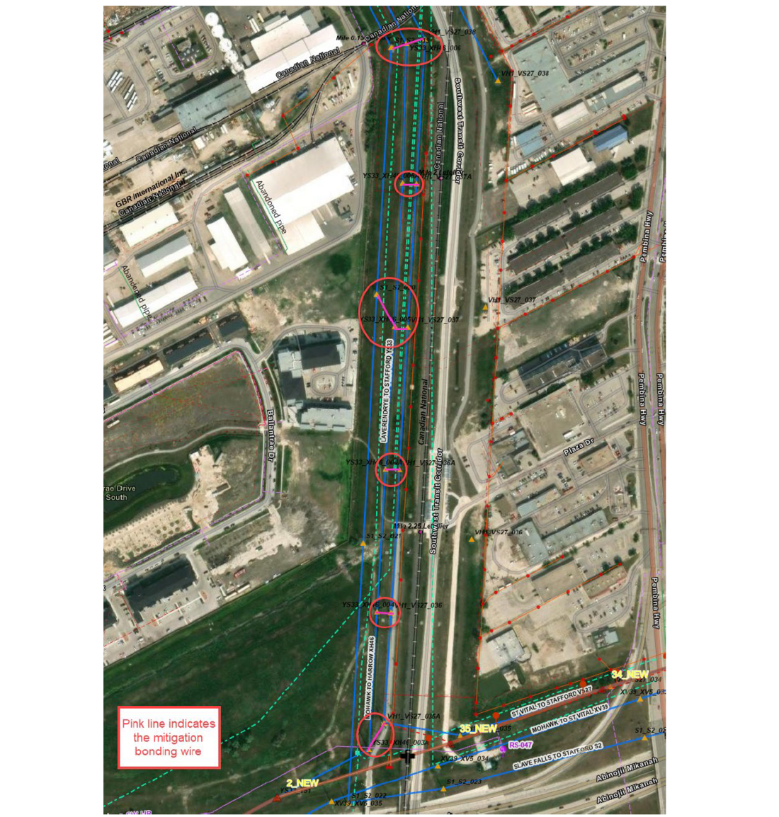
Figure 4 –Mitigation Plan
5. Conclusion
The Manitoba Hydro Southwest Winnipeg Transmission Improvement Project illustrates the significant challenges and innovative solutions related to AC interference in shared corridors between transmission lines and railway systems. This case study emphasizes the importance of early identification and mitigation of AC interference to ensure the safety of personnel, the reliability of railway signaling systems, and the integrity of power transmission infrastructure.
The project demonstrated the effectiveness of Manitoba Hydro’s two-step guideline for evaluating and mitigating AC interference minimizing interruption on utility operations. The first step involved a machine learning-based toolbox, which facilitated a quick and efficient preliminary assessment of induced voltages on railway tracks. This tool, developed using machine learning, enabled engineers to determine whether further detailed analysis was necessary. This proactive approach significantly reduced the time and resources required for initial assessments, allowing for timely decision-making during the design phase.
The second step consisted of a comprehensive engineering study using electromagnetic and grounding system simulation software to model the system under both steady-state and fault conditions. This thorough analysis confirmed the preliminary findings and identified specific scenarios where touch voltages exceeded safety limits during fault conditions. The study revealed that while steady-state induced voltages remained within acceptable limits, fault conditions, especially in winter, posed significant risks due to GPR.
The project proposed specific mitigation measures, including additional bonding in concrete foundations and interconnecting transmission lines within the corridor. These measures effectively distributed fault currents, reducing GPR and touch voltages to safe levels according to CNR specifications.
The success of this project can be attributed to its systematic and collaborative approach. By closely working with CNR, Manitoba Hydro ensured that the mitigation strategies were not only technically sound but also aligned with railway operational requirements. The validation of the software model through field measurements further reinforced the accuracy and conservatism of the simulations, instilling confidence in the proposed solutions. Additionally, the project highlighted the value of advanced tools, such as machine learning and electromagnetic simulation software, in addressing complex engineering challenges.
References
- The Effect of Overhead AC Power Lines Paralleling Ductile Iron Pipelines by Richard W. Bonds, P.E., March 2017
- C. Wang, X. Liang, and E. Adajar, "Evaluation and Mitigation of Electromagnetic Interference between Railways and Nearby Power Lines: A Review," IEEE Access, vol. 9, pp. 149609-149618, Nov. 2021.
- IEEE Standard 2746-2020, “IEEE Guide for Evaluating AC Interference on Linear Facilities Co-Located Near Transmission Lines”, 2020.
- A.H.A. Manders, G.A. Hofkens, and H. Schoenmakers, “Inductive interference of the signal and protection system of the Netherlands railways by high voltage overhead lines running parallel with railways,” CIGRE 25th Session, Paris, France, August 1974.
- R. A. Perala, “Impedance bond mitigation of inductive interference to railway wayside signal system,” Proc. of 17th Int. Symp. On Electromagnetic Compatibility, Singapore, March 2006.
- Principles and Practices for Inductive Coordination of Electric Supply and Railroad Communication/Signal Systems, A Report of the Joint Committee of the AAR and EEI on Inductive Coordination, September
- Mutual Design of Overhead Transmission Lines and Railroad Communication and Signal Systems, Volume 1: Engineering Analysis and Volume 2: Appendixes, EPRI Report EL-3301, Research Project 1902-1, October 1983.
- Utility Corridor Design: Transmission Lines, Railroads, and Pipelines, Volume 1: Engineering Analysis and Site Study and Volume 2: User’s Manual for Computer Program CORRIDOR, EPRI Report EL-4147, Research Project 1902-2, July 1985.
- CAN/CSA-C22.3 No.3-98, Electrical Coordination
- IEEE Standard 2746-2020, “IEEE Guide for Evaluating AC Interference on Linear Facilities Co-Located Near Transmission Lines”, 2020.
- G. Lucca, “Influence of railway line characteristics in inductive interference on railway track circuits,” IET Science, Measurement & Technology, vol. 13, no. 1, pp. 9-16, 2019.
- EPRI “Overhead Transmission Line Lightning and Grounding Reference Book 2021 (Gray Book)” PID: 3002021482, 2021
- C. Wang, X. Liang and E. P. Adajar, "A Systematic Approach for AC Electromagnetic Interference Study Between Railways and Nearby Power Lines," in IEEE Transactions on Industry Applications, vol. 59, no. 5, pp. 5527-5538, Sept.-Oct. 2023, doi: 10.1109/TIA.2023.3290572.
- M. N. S. K. Shabbir, C. Wang, X. Liang and E. Adajar, "A Novel Toolbox for Induced Voltage Prediction on Rail Tracks Due to AC Electromagnetic Interference Between Railway and Nearby Power Lines," in IEEE Transactions on Industry Applications, vol. 59, no. 3, pp. 2772-2784, May-June 2023, doi: 10.1109/TIA.2023.3234935.
- Guide to Engineering the Multiple Use of the Right of Way, EPRI Report 1013786, November 2007.
- F.P. Dawalibi, R. Southey, J. Ma, Y. Li, “On the Mechanisms of Electromagnetic Interference Between Electrical Power Systems and Neighboring Pipelines”.
- Power System and Railroad Electromagnetic Compatibility Handbook, EPRI Report 1012652, November 2006.
- Effects of current on human beings and livestock – Part 1: General aspects, IEC 60479-1, 2018.
- Guide for Safety in AC Substation Grounding, IEEE Standard 80, 2017.
- AREMA Communications and Signals Manual 2018