Suppression of gas pressure or tank diameter increase of GIS using natural-origin gas by combining FGM spacer and insulation coating technology
Authors
Kenji OKAMOTO, Hidetaka MASUI - Fuji Electric Co., Ltd., Japan
Naoki OSAWA - Kanazawa Institute of Technology, Japan
Katsumi KATO - N. I. T., Niihama College, Japan

Summary
Since the global warming potential (GWP) of SF6 gas, which has been used in gas insulated switchgear (GIS) and gas insulated transmission line (GIL), is so high as 24,300, its use will be restricted in the future . Currently, alternatives to SF6 gas, such as fluoronitrile (C4 FN) gas mixtures and dry air, are being applied. Dry air, in particular, is the most environmentally friendly because it has zero GWP and is easy to handle. Dry air is already used in GIS and GIL as a substitute for SF6 , but its insulating properties are about 30 40%, and to satisfy the same performance, it is necessary to increase the diameter of the insulating spacers supporting the high voltage conductor and the tank diameter or to increase the filling gas pressure. These will increase the energy required for production and ulti mately lead to increased CO2 emissions.
On the other hand, we have developed permittivity (ε)-functionally graded material (ε FGM) insulating spacers that can reduce the electric field strength. By applying FGM technology, we have achieved 30% reduction in the diameter of the insulating spacer and tank of conventional 245 kV class SF6 GIS and GIL. Therefore , we examined the lightning impulse flash over voltage LI FOV characteristics of the application of ε FGM insulating spacers to enhance the insulating properties of dry air and investigated the effect of improved insulating performance. As a result, it has been shown that compared to the conventional u niform permittivity spacer, the increase is 19% at 0.5 MPa abs and 27% at 0.6 MPa abs, and the rate of increase is comparable to that of SF6.
In this study, in order to find a method ology to further enhance the insulation properties, we examined the combination of a conventionally used insulation coating high voltage conductor and an ε FGM spacer. Epoxy paint was coat ed to the surface of the conductor to a thickness of about 100 μ m, and in combination with ε FGM insulation spacers, LI FOV was measured in the same way. The results showed that the LI FOV increased by 30% at 0.4 MPa abs and up to 47% at 0.6 MPa abs compared to the conventional uniform permittivity insulating spacer.
Furthermore, we estimated how much the dry air pressure could be reduced by applying FGM technology to existing 245 kV class insulation spacers. As a result, it was found that the filling pressure needs to be increased to more than 1.2 MPa abs to satisfy the insulation requirements with the conventional u niform permittivity spacer, whereas the filling pressure can be reduced to about 0.7 MPa abs by combining the resin coated high voltage conductor and FGM technology.
The combination of resin coated high voltage conductors and FGM technology will enhance for the increased gas filling pressure and insulation gap distance in the GIS when dry air is used and will prevent the equipment from becoming larger. As a result, it is expected to reduce energy consumption and CO2 emissions during manufacturing.
Keywords
Dry Air, Electrical insulation, ε-Functionally Graded Materials (ε-FGM), Insulating Spacer, Insulation Coating, Gas-Insulated Switchgear (GIS), Gas-Insulated Transmission Line (GIL)Since the global warming potential (GWP) of SF6 gas, which has been used in gas-insulated switchgear (GIS) and gas-insulated transmission line (GIL), is so high as 24,300, its use will be restricted in the future. Currently, alternatives to SF6 gas, such as fluoronitrile (C4-FN) mixtures and dry air, are being applied. Dry air in particular is the most eco-friendly because it has zero GWP. And it is easy to handle, because there is no toxicity. It is already used as a substitute for SF6 in GIS and GIL, but its insulation is about 30~40% [1]-[4]. In order to satisfy the same performance, it is necessary to increase the insulation distance by expanding the diameter of the insulation spacer supporting the high-voltage conductor and the tank diameter, and the equipment becomes large-sized. This is an issue when replacement of GIS in a narrow substation. As a method to increase the insulation of dry air, there is a method to increase the filling gas pressure, however, it is necessary to drastically increase it. Both methods increase the use of metal materials for tanks. Therefore, both increase the energy required for production and ultimately lead to an increase in CO2 emissions.
Under such circumstances, we have developed an actual size permittivity (ε) functionally graded material (ε‐FGM) insulating spacer, which can reduce the electric field strength of a conventional insulating spacer with uniform permittivity. By applying the FGM technology, the diameter of the insulated spacer and tank of the conventional 245 kV class SF6 GIS or GIL can be reduced by 30%. Therefore, we examined the lightning impulse flash over voltage (LI-FOV) characteristics of the application of ε-FGM insulating spacers to enhance the insulating properties of dry air and investigated the effect of improved insulating performance.
As a result, it has been shown that compared to the conventional uniform permittivity spacer, the increase is 19% at 0.5 MPa-abs and 27% at 0.6 MPa-abs, and the rate of increase is comparable to that of SF6 [5]-[15].
In this study, in order to find a technique for further enhance the insulation characteristics, the combination of the conventional resin coated high voltage (HV) conductor and ε-FGM spacer was examined. Epoxy paint was coated to the surface of the HV conductor to a thickness of more than 100μm, and in combination with ε-FGM insulation spacers, LI-FOV was measured in the same way. Furthermore, based on the results obtained, it was examined how the size of the insulating spacer, and the filling pressure of dry air could be reduced.
2. Insulation design of actual-size cone-type ε-FGM spacer
For ε-FGM, a 245kV class actual-size cone-type insulating GIS spacer was developed. Figure 1(a) shows the cross section of the actual-size cone-type ε-FGM insulating spacer. The outer diameter of the HV conductor was 90 mm and inner diameter of the grounded tank was 240 mm. The grounded tank configuration around the spacer was modified considering the actual GIS spacer. The permittivity distribution of the ε-FGM spacer was optimized by an inverse analysis technique using a newly developed electric field analysis method [13]. As shown in Figure 1(b), the inside of the spacer was divided into thin layers from #1 to #34 and the εr of each layer was obtained using the inverse analysis calculation. The initial εr uniform distribution was set to 4.0. As shown in Figure 1(c), the εr in the spacer was reduced in six steps from εr = 10 around the HV conductor to εr = 4 around the grounded tank.
Figure 2(a) shows the electric field distribution around the conventional uniform permittivity spacer with the same shape as the ε-FGM spacer and a constant εr = 4, whereas Figure 2(b) shows the electric field distribution around the ε-FGM spacer in Figure 1. The electric field stress at shield edge of the HV conductor on the concave side of the uniform spacer is defined as 1.0 a.u., which is higher than those on the coaxial HV conductor and spacer surface on the concave and convex sides. In contrast, the electric field stress at the same point of the ε-FGM spacer is reduced to 0.74 a.u., which is 26 % lower than that of the uniform spacer and almost equivalent 0.77 a.u. on the coaxial HV conductor. The electric field stress on the spacer surface on the convex side of the uniform spacer is increased from 0.50 a.u. to 0.73 a.u., which implies that the electric field distribution in dry air around the ε-FGM spacer is equalized owing its permittivity distribution of ε-FGM.
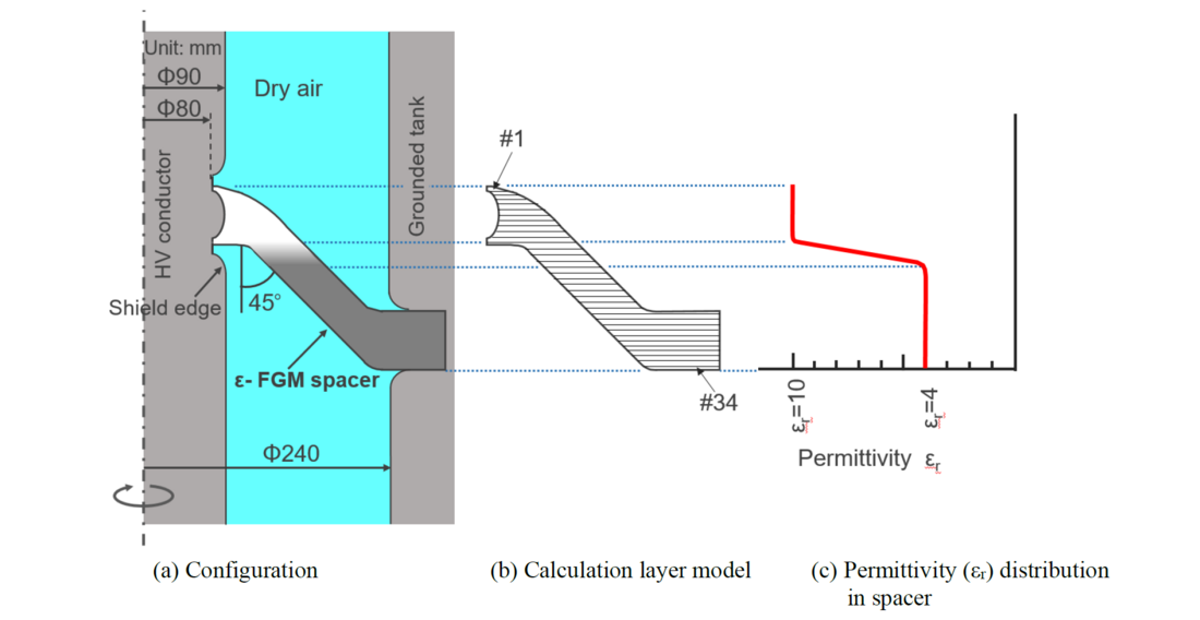
Figure 1 - 245kV class actual-size ε-FGM insulating spacer model
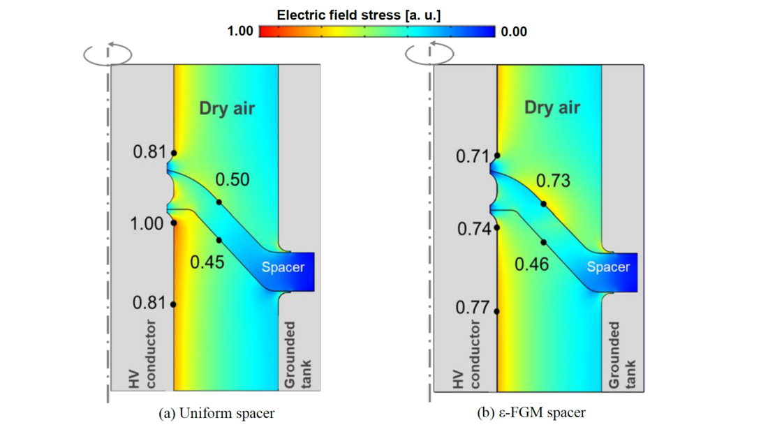
Figure 2 - Calculated electric field distribution in dry air insulated GIS with spacer
3. Actual size cone-type ε-FGM spacer fabrication
To fabricate spacers with a graded change in ε (permittivity), two epoxy composites with different permittivity were prepared using the raw materials listed in Table I. SrTiO3 (εr = 332) and SiO2 fillers (εr = 4) were used for the high and low permittivity epoxy composites, respectively. The permittivity was changed by varying the ratio of these two composites and sequentially casting in the mold to fabricate cone-shaped ε-FGM insulating spacers with permittivity gradient from εr=10 to εr=4. For comparison, uniform spacers were also produced with a permittivity of 4.
| High εr composite | Low εr composite | |
|---|---|---|
| Epoxy resin | Bisphenol-A | |
| Hardener | Anhydride-type | |
| Filler | SrTiO3 | SiO2 |
| Mean diameter | 1.0-1.5μm | 1.5μm |
| Relative permittivity (εr) | 332 | 4 |
Figures 3(a) and (b) show a uniform spacer of εr=4, and ε-FGM insulating spacer of εr=10-4. In Figure 3(b), the white and black colored regions correspond to εr=10, and εr=4, respectively, and the gray color region between them is a permittivity graded part.
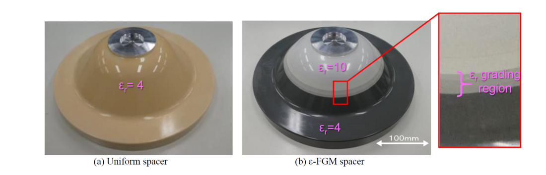
Figure 3 - Fabricated actual size cone-type (a) Uniform spacer and (b) ε-FGM spacers
4. LI-FOV test of connected FGM spacer and insulation coating HV conductor
Figure 4 shows the schematic of the LI-FOV measuring apparatus for 245kV class actual size ε-FGM insulating spacer and connected HV-conductor. Epoxy paint was applied to the HV conductor with a thickness of more than 100 μm. These were installed in the pressure tank filled with dry-air at 0.4 or 0.6 MPa-abs and applied to negative standard (-1.2/50μs) LI voltage.
At present, the LI-FOV of the ε-FGM insulating spacer was measured by connecting the HV conductor without and with the insulation coating. The applied voltage started from a value of about 0.5 a.u. The voltage was increased stepwise by 10kV until the breakdown occurred, and the voltage value at the first breakdown was defined as FOV.
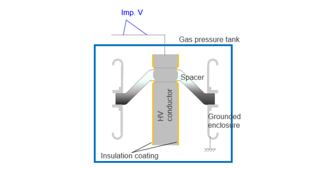
Figure 4 - LI flashover voltage measuring apparatus for actual size insulating spacer
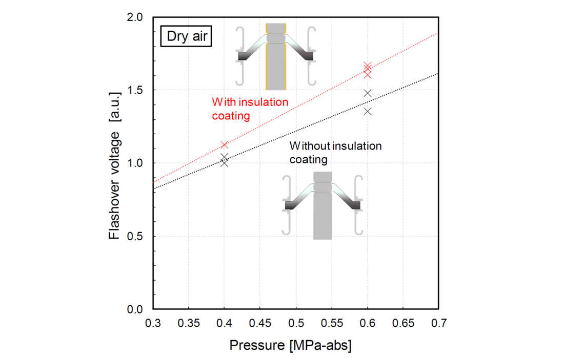
Figure 5 - LI flashover voltages of actual size ε-FGM insulating spacers with various configurations in dry air under 0.4 and 0.6 MPa‐abs

5. LI-FOV test results and discussion
Figure 5 shows the measurement results in the case that the HV conductor without insulation coating (black) and with insulation coating (red) are connected to the ε-FGM insulation spacer in dry air gas pressures of 0.4 and 0.6MPa-abs. At 0.6MPa-abs in dry, the with insulation coating showed FOV in the range of 1.60 to 1.67 a.u., whereas the without insulation coating showed in the range of 1.35 to 1.48 a.u. at 0.4 MPa-abs, the with insulation coating HV conductor showed FOV of 1.13 a.u., whereas the without insulation coating HV conductor showed in the range of 1.00 to 1.04 a.u. Therefore, it was experimentally verified that the FOV of the combination of ε-FGM spacer and with insulation coating HV conductor increased more than that of the combination of ε-FGM spacer and without insulation coating HV conductor between 0.4 and 0.6 MPa-abs, and the average of the FOV increased by the insulation coating whereas was 16 % higher at 0.6 MPa-abs and 10 % higher at 0.4 MPa -abs.
The flashover characteristics are discussed in terms of flashover traces in dry air. Figure 6 shows a flashover trace in a connected configuration of the ε-FGM insulating spacer and the HV-conductor without the insulation coating. As shown in Figures 6(a), (b) and (c), there were three types of discharge patterns: discharge from the concave-side coaxial HV conductor to the grounded enclosure, from the coaxial HV conductor shield edge to the spacer surface near the grounded enclosure and the concave-side coaxial HV conductor to the spacer surface near the grounded enclosure. However, in the case of the connection configuration between the ε-FGM insulating spacer and the HV conductor that has the insulation coating, all the discharges from the coaxial HV conductor on the concave side of the spacer to the ground enclosure as shown in Figure 7.
In the HV conductor shield edge, the electric field strength is relaxed by the FGM insulation spacer, and the electric field strength on the separated conductor becomes the highest as shown Figure 2(b). However, there is a possibility of flashover in the HV conductor shield edge, because the discharge is generated by the micro defect. On the other hand, when the insulation coating is applied, the electron emission at the micro defect is suppressed. Therefore, it is considered that flashover tends to occur in the HV conductor region which is distant from the spacer where the electric field strength is the highest.
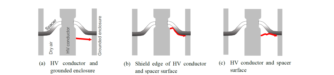
Figure 6 - LI flashover traces of case of without insulation coating HV conductor

Figure 7 - LI flashover traces of case of insulation coating HV conductor
Figure 8 shows the LI-FOV at 0.6 MPa-abs for various configurations. The leftmost bar shows the estimated initial FOV based on the previously shown results of the conventional uniform spacer in dry air [5]. Comparing this value and present FOV measurement result (average value), it is improved by 27% using only FGM spacer (both are conductors without insulation coating). The FOV increased up to 47% by combining the insulation coating conductor with the FGM spacer. It was clarified that the FOV could be drastically improved by combining FGM spacer and insulation coated conductor.
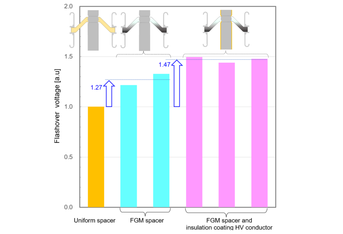
Figure 8 - LI flashover voltages of actual size insulating spacers with various configurations in dry air under 0.6 MPa‐abs
6. Considerations for busbar gas pressure or tank diameter
In the previous studies, based on the FOV characteristics of the HV conductor without insulation coating and the insulation spacer and some references, the FOV characteristics when combined with the insulation coating HV conductor were estimated [16]-[17]. This time, the dry air filling pressure and tank diameter in the single-phase insulation bus was reinvestigated based on the result of actual measurement.
First, the electric field distribution of the insulating spacer with the existing diameter, i.e., before the 30 % reduction, was obtained from the electric field analysis of the uniform spacer and ε-FGM spacer, respectively, and the results are shown in Figure 9. The maximum electric field stresses of the existing sizes of insulating spacers are both reduced by approximately 30%. Subsequently, the gas pressure at which the withstand voltage was satisfied was estimated under various conditions.
Table II lists the maximum electric field stress, LI-FOV and gas pressures at which insulation can be achieved under each condition. When insulating only with uniform spacers in dry air, a gas pressure of at least 1.2 MPa-abs is required. Second, the gas pressure was estimated using the conventional method of combining the insulation coating high-voltage conductor and uniform spacer. Previous studies have shown that resin coatings can increase FOV by approximately 20 %, depending on the coating thickness [16]- [17]. Here, the pressure reduction was estimated on the assumption that it could be increased by 10 %. It was estimated that the pressure could be reduced to 1.08 MPa-abs owing to the improved insulation properties of the insulation coating; however, the effect was not enough.
Next, based on the newly measured results, the case of applying the FGM spacer was investigated. As a result, it was shown that insulation was possible even when the pressure was reduced to 0.82 MPa-abs. Furthermore, the combination of the insulation coating HV conductor and the ε-FGM spacer further reduces the pressure, and it was shown that insulation of about 0.70 MPa-abs was possible even in the existing tank size.
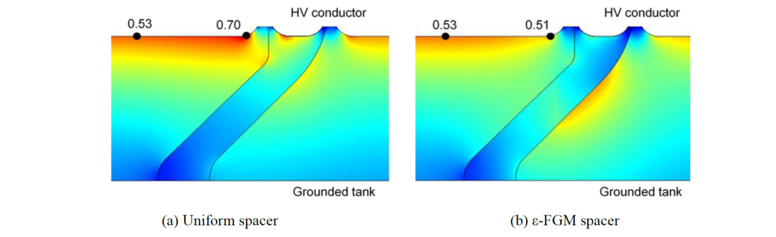
Figure 9 - Electric field stress distribution of existing size 245 kV class insulating spacer
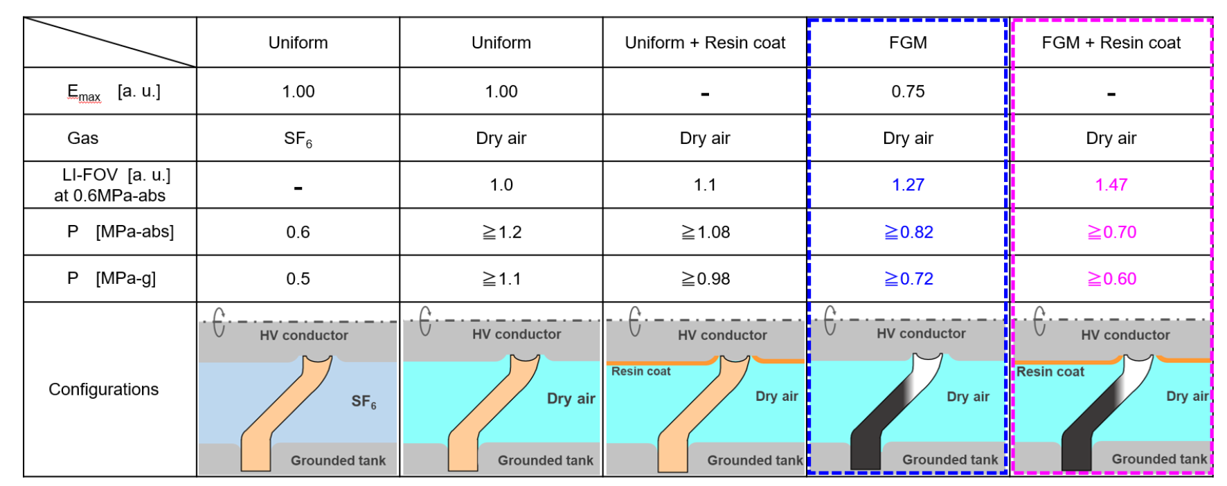
Table 2 - Comparison of Emax and filing gas pressure of existing size 245kV class single phase busbar
Figure 10 presents a comparison of the filling gas pressures for each case. By the combination of the ε-FGM insulating spacers and the insulation coating HV conductors, it is possible to insulate existing tank sizes with dry air, which has limited insulating properties, by increasing the filling pressure by only 0.10-0.22 MPa-abs close to the pressure level of present operating SF6 gas GIS.
In addition, the required tank diameter was estimated for each condition as described above, if the tank were to be insulated with dry air at a gas pressure of 0.6 MPa-abs, the same as SF6. The results are shown in Figure 11. In the case of uniform spacers, the tank diameter was estimated to increase significantly by approximately 78 %. In contrast, the tank diameter increase was limited to 26 % by applying the FGM technique. Furthermore, the application of FGM spacers to insulation coating conductors limits the increase of the tank diameter only to 15 %.
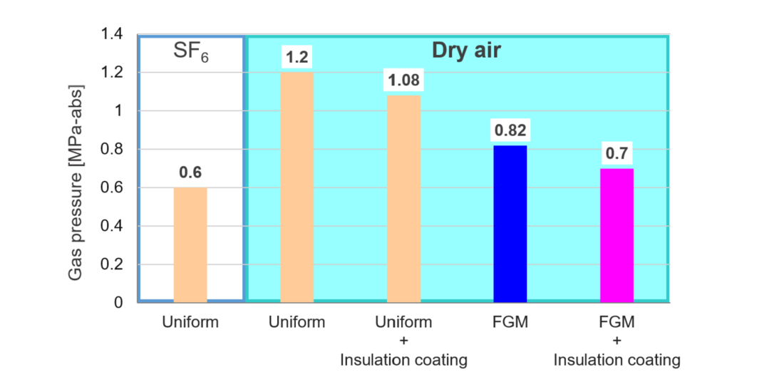
Figure 10 - Comparison of filling gas pressure.by application of FGM techniques
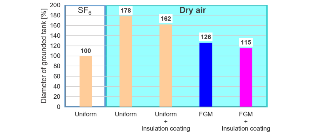
Figure 11 - Comparison of tank diameter by application of FGM techniques (at 0.6MPa-abs)
7. Conclusions
The findings of this study are summarized as follows:
- In order to find a methodology to improve the insulation properties of dry-air insulation GIS and GIL, a combination of the insulation coating HV conductor and the ε-FGM insulating spacer was examined. The results showed that the LI-FOV dramatically increased by 30% at 0.4 MPa-abs and 47% at 0.6 MPa-abs compared with the conventional uniform permittivity insulating spacer.
- The reduction effect of dry air pressure by applying FGM technology to the existing 245kV class insulating spacer was estimated. As a result, it was found that the filling pressure could be reduced to about 0.7 MPa‐abs by combining the insulation coating HV conductor and the ε-FGM insulating spacer, while it was necessary to increase the filling pressure to more than 1.2 MPa‐abs to satisfy the insulation requirement in the conventional uniform permittivity insulating spacer.
- To insulate with the same gas pressure as SF6 would require an increase in diameter of the existing tank by approximately 78 %. It is estimated that the application of FGM technique can limit the increase in size to 26 %, and the combination of insulation coating HV conductors would limit the increase to increase only 15 %.
In the conventional insulating spacer, the insulation performance of the connecting region with the HV conductor and its vicinity is lower than that of the HV conductor arranged coaxially, and the insulation design has been limited by this region. The ε-FGM spacer and insulation coating techniques can effectively improve the insulation performance of this region, contributing to the substitution from SF6 gas to dry air. At present, the data obtained is limited and will be further improved and expanded to increase the accuracy of the insulating design.
The application of these technique to the insulating spacers of GIS or GIL is considered to compensate for the increased gas pressure, insulation gap distance and equipment size when dry air is used. In particular, they are expected to contribute to the replacement of narrow substations (e. g., indoor, underground, mountainside, offshore, etc.) that require the same size. It is also anticipated to reduce the production energy and CO2 emissions.
References
- M. Kuschel. L.-V. Badicu, J. Christian, M. Kieper, K. Kunde, U. Prucker and J. Riedl, “First F-gas-free and climate-neutral insulated 420 kV GIS busducts installation at TransnetBW” (CIGRE Paris Session, B3-11082, 2022).
- T. Uchii, D. Yoshida, S. Tsukao, K. Taketa and K. Tsuboi, “Recent Development of SF6 Alternative Switchgear Using Natural-Origin Gases in Japan” (CIGRE Paris Session, A3-10643, 2022).
- N. Nakamura, S. Tsukao, T. Nishioka, K. Taketa, T. Uchii and H. Hama. “Management of SF6 gas leakage from substation equipment and technical guidelines on application of substation equipment using SF6 alternative gases in Japan” (CIGRE Paris Session, B3-10736, 2022).
- “Dry Air, CO2 and N2/SF6 mixtures for gas insulated systems” (CIGRE Technical Brochure, No.730, 2018).
- K. Okamoto, N. Hayakawa, K. Kato, N. Osawa, M Kozako and H. Okubo, “Enhancing Electrical Insulation Performance of Insulating Spacers using Functionally Graded Materials in Natural-Origin Gas GIS” (CIGRE Paris Session, D1-11054, 2024).
- K. Okamoto, N. Hayakawa, M. Hikita, H. Okubo, K. Kato and N. Osawa. “Development of Sophisticated Cone-Type Insulating Spacer for 245 kV Class GIS by Functional Insulating Materials” (CIGRE Paris Session, D1-10648, 2022).
- K. Kato, K. Kimura, S. Sakuma and H. Okubo, “Functionally Gradient Material (FGM) For GIS Spacer Insulation” (12th International Symposium on High Voltage Engineering (ISH), vol. 2, pp.401-404, 2001).
- K. Kato, M. Kurimoto, H. Adachi, S. Sakuma and H. Okubo, “Impulse Breakdown Characteristics of Permittivity Graded Solid Spacer in SF6” (IEEE Conference on Electrical Insulation and Dielectric Phenomena (CEIDP), pp.401-404, 2001).
- H. Okubo, H. Shumiya, M. Ito and K. Kato, “Insulation Performance of Permittivity Graded FGM (Functionally Graded Materials) in SF6 Gas under Lightning Impulse Conditions” (Conference Record of the 2006 IEEE International Symposium on Electrical Insulation (ISEI), IEEE, pp.332-335, 2006).
- H. Okubo, H. Shumiya, M. Ito and K. Kato, “Optimization Techniques on Permittivity Distribution in Permittivity Graded Solid Insulators” (Conference Record of the 2006 IEEE International Symposium on Electrical Insulation (ISEI), IEEE, pp.519-522, 2006).
- H. Okubo, K. Kato, N. Hayakawa, M. Hanai and M. Takei, “Functionally Graded Materials and their Applications to High Electric Field Power Equipment” (CIGRE SC D1 – Colloquium in Hungary Budapest, 2009).
- N. Hayakawa, K. Kato, H. Okubo, H. Hama, Y. Hoshina and T. Rokunohe, “Electric Field Grading Techniques in Power Apparatus Using Functional Materials” (CIGRE Paris Session, D1-309, 2014).
- K. Kato, H. Kojima, N. Hayakawa, H. Mitsudome, H. Yanase, K. Okamoto and H. Okubo, “Inverse Analysis of Permittivity Distribution of FGM (Functionally Graded Materials) Insulator in Gaseous Insulation System” (21st International Symposium on High Voltage Engineering (ISH), 2019).
- N. Hayakawa, K. Kato, H. Okubo, K. Watanabe, K. Okamoto, Y. Hoshina and K. Adachi, “Electric field grading and breakdown voltage enhancement of gas insulated power apparatus with functionally graded materials (FGM)” (CIGRE SCIENCE & ENGINEERING, No. 016, pp. 6-12, 2019).
- K. Okamoto, N. Hayakawa, M. Hikita, H. Okubo, K. Kato, N. Osawa. K. Watanabe, and K. Adachi, “Distinctive Downsizing of Cone-Type Insulating Spacer for 245 kV Class GIS by Functional Insulating Materials” (CIGRE Science & Engineering, No. 024, 2022).
- H. Goshima, S. Okabe, T. Ueda, F. Morii, N. Yamachi, K. Takahata and M. Hikita, “Fundamental insulation characteristics of high-pressure CO2 gas for gas-insulated power equipment - effect of coating conductor on insulation performance and effect of decomposition products on creeping insulation of spacer -” (IEEE Transactions on Dielectrics and Electrical Insulation, vol. 15, No. 4, pp.1023-1030, 2008).
- “Optimized Gas-Insulated Systems by Advanced Insulation Techniques” (CIGRE Technical Brochure, No.571, 2014)