A Novel Mathematical Approach to Modernizing Outdoor Substation Design by Incorporating Probabilistic Design Principles in Substation Equipment Bays
Authors
Abraham J.S. GROENEWALD - Discipline of Electrical Engineering, University of KwaZulu-Natal, Durban, 4041, South Africa
Mohamed F. KHAN - Centre for Power and Energy Systems, University of KwaZulu-Natal, Durban, 4041, South Africa

Summary
This paper presents a fully developed novel mathematical approach for the design process of Air Insulated Switchgear (AIS) substations for voltages above 6,6 kV, using strained and suspended stranded flexible conductors. It focuses on optimizing the positioning and spatial separation of outdoor bay equipment based on two opposing pre-set criteria, viz. the choice of Basic Insulation Level (BIL) that sets the minimum separation, and the design fault level that sets the maximum separation. Both have associated influences that are investigated and taken into account by providing a framework that results in a fairly narrow range of dimensions to consider, this approach aims to facilitate rapid convergence to an optimized design, and in doing so, improve working efficiency. This paper, will provide the framework for the analysis, as well as the mathematical models for a variety of outdoor substation infrastructure with optimized clearances, resulting in the minimum, lower bound, values. The maximum, or upper bound values, are determined by considering the constraining effects that the system fault level values have on the maximum spatial separation between equipment. These are represented by the maximum dynamic electromagnetic tensile forces acting on the equipment terminals during a fault. Comparing the results of the calculations for equipment spatial separation with the current standard drawings, there is a clear case for a significant reduction in the substation equipment bay footprint without compromising safe electrical and operational clearances. The results also demonstrate that the arrangements can be made mechanically strong enough to withstand the expected long-term fault current creep and their accompanying effects.
Keywords
Electrical Clearances, Infrastructure Spatial Separation, Lower and Upper Bounds, Outdoor Air Insulated SubstationsNomenclature
Unique Identifier | Description | Unique Identifier | Description |
Ya | Distance between earth blade of isolator and frame of equipment (purely a mechanical clearance) | Sbc | Sag Busbar Conductor |
Ya1 | Distance between the frames of equipment | T | Tension |
Ya2 | Distance between the mechanism boxes of equipment (circuit breakers and isolators) | ta | Centre Line to edge of Tank |
Ya3 | Distance between the foundations of equipment | tr | Transformer |
a | Unknown dimension to be calculated from supplies parameters | tt | Centre Line to end of Equipment Terminal |
acb | Insulator distance across circuit breaker | U1 | Unknown dimension 0 |
ar | Centre Line to end of Arm (isolator) | U1 | Unknown dimension 1 |
b | Unknown vertical dimension to be calculated from supplies parameters | U2 | Unknown dimension 2 |
ba | Bay | U3 | Unknown dimension 3 |
bb | Busbar | U4 | Unknown dimension 4 |
c | Unknown dimension to be calculated from supplies parameters | Ue | Unknown dimension to earth |
ca | Shunt Capacitor | vt | Voltage Transformer |
cb | Circuit Breaker | X | Measurement transverse to the equipment bay |
cc | Coupling Capacitor | Xcl | Distance between tank centre-line of conservator above plinth |
Ce | Standard phase‒to‒ground clearance | Xhv | Distance between high voltage bushings |
cl | Centre Line to edge of coolers | Xlv | Distance from tank centre-line to low voltage bushing terminals |
Cp | Standard phase‒to‒phase clearance | Xls | Sub-conductor spacing |
ct | Current Transformer | Xsp | Conductor phase spacing |
cvt | Capacitor VT | Xta | Distance between tank centre-line and tank edge |
Cwh | Horizontal working clearance | Y | Measurement along the equipment bay |
d | Unknown dimension to be calculated from supplies parameters | Ya | Distance between earth blade of isolator and frame of equipment (purely a mechanical clearance) |
dc | Conductor diameter | Ya1 | Distance between the frames of equipment |
dmin1 | Minimum distance to earth | Ya2 | Distance between the mechanism boxes of equipment (circuit breakers and isolators) |
dmin2 | Minimum distance to live part | Ya3 | Distance between the foundations of equipment |
e | Centre Line of connecting terminal to edge of insulator connecting box | Ycl | Distance between tank centre-line to conservator edge |
eb | Centre Line to end of Earth Blade | YK | Width of clamp |
eq | Equipment type | Yo | Overall length of the equipment |
es | Earth‒switch | Yi | Distance of the edge of central interrupter actuating box of Tee or Vee type multiple chamber circuit breaker from centre-line |
f | Unknown dimension to be calculated from supplies parameters | Yta | Distance between tank centre-line to tank edge |
fo | Centre Line to edge of Foundation | Z | Measurement perpendicular to the X-Y plane (Height above the equipment support foundation) |
fr | Centre Line to edge of steel support frame | Zac | Difference between Zpgmax and Zpgmin |
hl | High Level (for example, terminal of CB, LT, etcetera) | Zb | Height of central interrupter actuating box of Tee or Vee type multiple chamber circuit breaker |
Ik | Short-circuit current | Zbb | Height of the busbar |
is | Isolator | Zcl | Height of the top of conservator above plinth |
K | Overall clamp assembly dimension allowance | Zeb | Height of the earth blade above foundation |
kc | Empirical proportionality factor depending on conductor’s construction and flexibility | Zfr | Height of the top of steelwork support above foundation |
ll | Low Level | Zhv | Height of the high voltage bushing terminal above plinth |
lt | Line Trap | ZK | Length of clamp |
mb | Centre Line to edge of Mechanism or Terminal Box | Zlv | Height of the low voltage bushing terminal above plinth |
o | Overall | Zmv | Height of the medium voltage bushing terminal above plinth |
pg | Pantograph Isolator | Zo | Overall height of equipment |
pi | Post Insulator | Zpgmax | Maximum height of panto-isolator trapeze above foundation |
R | Radius (live part of apparatus) | Zpgmin | Minimum height of panto-isolator trapeze above foundation |
Rc | Minimum conductor bending radius | Zta | Height of tank above foundation |
sa | Surge Arrester | Ztt | Height of terminal above foundation |
1. Introduction
The focus of this research is twofold. It is primarily about investigating the possibility of providing a dimensionally optimized Air Insulated Substation (AIS) that employs stranded flexible conductors, resulting in the smallest possible footprint without compromising safe electrical clearances and operating spacing. Secondly, but also a critical and often overlooked issue, is to establish that the resulting layout is mechanically strong enough to cater for expected long-term fault current creep and its accompanying effects.
It is in the first instance, impossible to separate the main concepts of this study from system steady-state over-voltages that form part of temporary over-voltages that can cause insulation failure, short circuits, damage to equipment, etc. Maximum operating voltages (Um) are usually 5-10 % above the nominal voltage (Un), depending on the voltage range. Voltage range I refers to voltages between 1 kV and less than 300 kV, whilst voltage range II refers to voltages between 300 kV and 800 kV. [1]
Most electrical engineering challenges in substation design are related to insulation coordination [1]. A number of definitions could be used to define insulation coordination. First, the goal should be defined. The goal of the insulation within a substation environment is fundamentally focused on limiting the risk of insulation breakdown. It is almost impossible to completely prevent the breakdown of insulation, but carefully selecting the insulation strength and insulating gap geometry to improve the withstand capability of the system, is directly linked to the probability of insulation breakdown. The breakdown of air is probabilistic in nature, and has been found to follow a normal or Gaussian distribution [1][2]. Furthermore, when considering the anticipated over-voltages and the acceptable risk of failure, the selection of insulation strength could be defined more accurately. When surge protective devices are included in the selection criteria, the goal is defined even better [3][4][5].
An often-overlooked issue, particularly in cases where standard substation bay arrangements that were created years back and are still being implemented, is that of fault current creep over extended periods. Standards are applied without sufficient due consideration of the associated effects on the integrity of the design. This is not in terms of the equipment's electrical ratings themselves, but on the short circuit mechanical effects on the equipment terminals. Short circuits in multi-phase systems generate electromagnetic tensile forces that rip at the equipment terminals, especially when more than one conductor is used per phase.
2. Background
The motivation for and purpose of this paper is to provide a reliable and mathematically rigorous means for safely reducing the spatial separations between substation equipment in order to reduce the overall substation footprint, as illustrated in Figure 1.
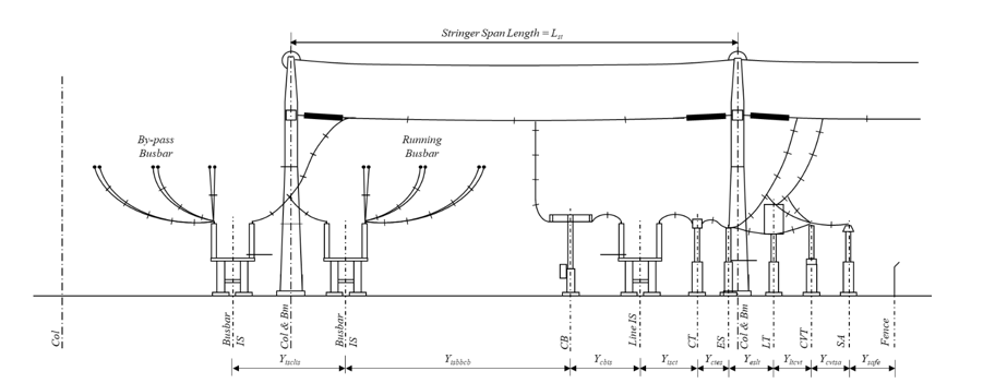
Figure 1 - Typical equipment bay orientation along the X‒, Y‒ and Z‒ axes
This paper deals with the spatial separation of only the primary equipment, and not the equipment in relation to the superstructure supporting overhead stranded and suspended flexible conductors that constitute the second and third levels of conductors’, characteristic of AIS overhead strung conductor systems. The paper covers the two main issues in substation design, that of clearances which determine lower bound minimum values, and that of fault level which determines the upper bound maximum values.
2.1. Lower Bound Minimum Separation – Electrical Clearances
Many substations in operation today were designed using legacy methodologies that are still in use. These methods took advantage of reduced first-cost “opportunities” allowed by existing installation codes and standards at that time and were based on essentially meeting clearances calculated using deterministic methods to account for uncertainties in the assumptions made. Deterministic clearance calculations refer to a method for dimensioning electrical air clearances based on fixed, conservative design values rather than probabilistic or statistical risk-based criteria. It assumes predefined worst-case electrical and environmental conditions and applies explicit safety margins to ensure dielectric withstand capability under all credible service conditions, resulting in conservative clearance values that must be met as a minimum or exceeded.
Fairly recent reviews of impulse withstand levels (IWL) for existing external insulation on outdoor equipment, associated with various voltage levels, have shown that these withstand levels yield very high insulation margins [6][7]. Current practice is therefore to apply probabilistic clearances with appropriate insulation grading, leading to smaller insulating gaps and therefore reduced dimensions.
In the same manner, it is proposed that the probabilistic approach that is implemented on equipment be considered for the sequential separation gaps between different equipment with coordinated insulation grading, explicitly considering [1]:
- Statistical distributions of over-voltages
- Statistical distributions of insulation strength
- Defined target risk of failure (acceptable outage probability)
The probabilistic method is based on the statistical overlap between stress distribution and strength distribution [1], where stress distribution is a probability distribution of electrical stresses (e.g., lightning impulse, switching impulse, power-frequency over-voltages), while strength distribution is a probability distribution of insulation withstand levels for a given clearance. As stated above, these follow a Gaussian Distribution, an extract of which is shown in Table 1.
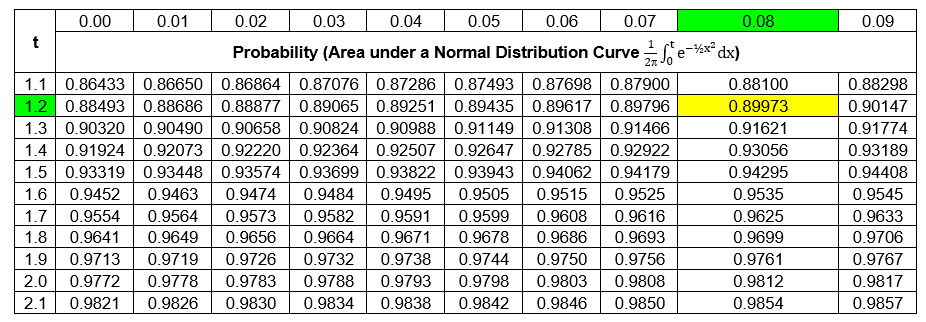
Table 1 - Area under normal distribution curve (PDC) vs t (extract) [8]
Reference [1] shows that for a normal distribution; the following relationship is applicable:
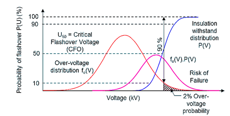
Figure 2 - Graphic of the evaluation of the risk factor [1]
(1)
Where:
| IWL | = | Impulse withstand level, Lightning Impulse Withstand Level (LIWL) or Switching Impulse Withstand Level (SIWL) |
| UCFO | = | Critical flash‒over value (kV) |
| t | = | The function value of the normal distribution curve (or value of the independent variable associated with a given area under a normal distribution curve) |
| = | Standard deviation of voltages in %. in the range of 2 to 3% for lightning impulses, and for switching impulses ranges between 5 and 7% |
UCFO for a given impulse withstand level (IWL) is hence determined as follows:
(2)
From Table 1, the closest value to 0.9 (90%) occurs in the row where t = 1.2, and column where t = 0.08. The total value for t is there the sum of these two, viz. 1.28.
A large portion of the voltage levels have more than one standardized impulse withstand level, derived from a number of criteria. It is therefore possible to choose an impulse level other than the normal standard value based on the following:
- Maximum system voltage (Um - highest voltage for equipment)
- Statistical analysis of expected over-voltages
- Insulation strength characteristics
- Required safety margins (
)
The resulting impulse withstand voltages become the standard insulation levels used for equipment testing.
(3)
Where:
= Expected maximum lightning or switching overvoltage [kV]),
= safety margin accounting for statistical dispersion and uncertainties

Table 2 - Correlation between standard lightning and switching impulse withstand voltages (Extract [1])
LeRoy – Gallet [1][9][10] have shown that UCFO can be related to the separation distance (s) of an insulation gap via a constant called the Gap Factor (Kg). This factor depends on the geometry of the insulating gap and is related to the 50% Critical Flash‒Over value. The LeRoy – Gallet equation is provided in (4).
(4)
Typical phase-to-earth Kg values are provided in Table 2.
Kg | = | Gap factor (50% Critical flash‒over value [kV]), |
t | = | The function value of the normal distribution curve (or value of the independent variable associated with a given area under a normal distribution curve), |
s | = | The length of the insulating gap (m) |
Some typical Gap Factor (Kg) values are provided for phase-to-earth and phase-to-phase geometries in Tables 3 and 4, respectively.
Configuration | Kg |
Rod – Plane (worst case) | 1.00 |
Conductor – Plane | 1.15 |
Rod – Structure | 1.20 |
Conductor – Lateral structure | 1.45 |
Conductor – Rod (6 m gap) | 1.90 |
Configuration | Kg |
Ring – ring or large smooth electrodes | 1.80 |
Crossed conductors | 1.65 |
Rod – rod or conductor – conductor (along the span) | 1.62 |
Supported busbars (fittings) | 1.50 |
Asymmetrical geometries | 1.45 |
For an optimised design therefore, it is necessary to determine the smallest clearances that will still provide acceptable reliability and safety for maintenance, as well as the best techno-economic solution through proper insulation co-ordination. Safety sectional clearances, however, cannot be compromised. From (4), the associated gap distance () is made the subject:
(5)
By selecting the appropriate IWL (LIWL or SIWL) and gap factor (Kg), the associated optimised clearances can be determined, and safety factors are therefore unnecessary.
2.2. Upper Bound Maximum Separation – Fault Current
With reference to the second, opposing criterion, viz. that of fault current (Ik2"), increase of generating capacity and evolving interconnected systems are usually associated with a corresponding increase in fault level, particularly where high-inertia rotating machines are concerned [11][12]. Although not an undesirable consequence in itself, since it provides stability to the system, fault level does become a major problem when the equipment's dynamic mechanical ratings and overall design parameters are exceeded [13][14]. Generating capacity and fault level in South Africa have been shown to follow an exponential relationship over time, as illustrated in Figure 2. This graphic is generated from data provided in [11]. This is also borne out in a 2021 investigation [12].
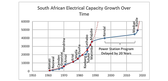
Figure 3 - South African grid capacity increase (1950-1990) [11]
The upper bound maximum equipment separation limit is determined by the maximum electro-mechanical forces that can be exerted on the terminals of the substation outdoor apparatus during a fault condition [13][14]. Each item of primary plant has a maximum dynamic design capability determined and provided by the manufacturer.
The physics is governed by the well-known Biot-Savart law that associates current flow with a force between two parallel conductors. This law is illustrated in (6).
(6)
For a given fault current (Ik2"), conductor phase spacing (Xcs) and sub-conductor span length (ls see Figure 6), the magnitude of the characteristic electro-mechanical tensile force (F) developed in the conductors, is directly proportional to the square of the short-circuit current () and the length of conductor (Yc) it flows through, and inversely proportional to the phase spacing (Xcs). This force is transferred equally to the terminals of the equipment pairs during fault conditions [13]. The unit of this force is Newtons per metre (N/m). The total force therefore is obtained by simply multiplying the Newton per metre force value by the length of the conductor through which the fault current flows.
(7)
Yeq1eq2 = Centre-line equipment separation (m)
The typical arrangement to be applied in this study is provided in Figure 4.
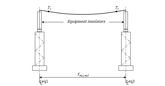
Figure 4 - Typical elevation on bay equipment separation
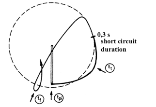
Figure 5 - Pinch Force (Fpi), Swing-out (Ft) Force and Drop Force (Ff) - Movement of a flexible conductor during and after a line-to-line short-circuit [13][14]
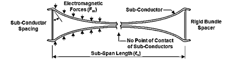
Figure6 - Pinch Force (Fpi) in 2 × conductor bundle [13][14]
Three force transitions occur from fault inception to fault clearance, as illustrated in Figure 5. The transition moves from the pinch force (Fpi) to the swingout force (Ft) and then finally to the drop force (Ff) [7]. The first (Fpi) is, however, only applicable where more than one conductor is employed per phase and are separated by a suitable distance to meet current-carrying and corona criteria, as shown in Figure 6.
To demonstrate the effect of sub-span length (ls) on pinch force, pinch force is plotted against sub-span length for a given multi-conductor bundle. The plot shows that very high pinch forces occur at low sub-span lengths. The maximum values occur at sub-span lengths where parallel sub-conductors are restricted to only just touch each other, and are presented in Figure 7 at the peaks in each of the curves, self-generated from a simulation program based on [13][14].
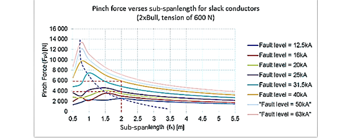
Figure 7 - Relationship between Pinch Force (Fpi) and sub-span length (Self-generated based on [13][14])
Figure 7 shows that for multi-conductor bundles per phase, it would be highly advisable to have sub-span lengths of 2 metres or more, but this is also dependent on the fault current. Figure 7 demonstrates the dominance of the pinch force when multiple conductor bundles are used. This image was self-generated from a simulation programme based on [13][14].
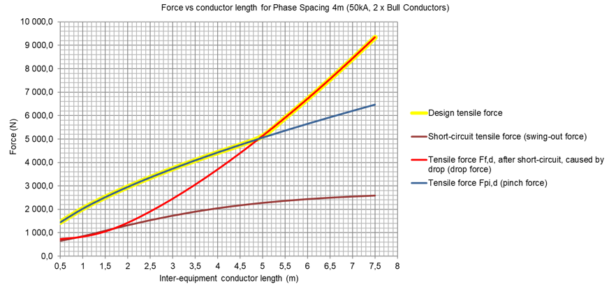
Figure 8 - Pinch Force (Fpi), Swing-out Force (Ft) and Drop Force (Ff) vs conductor length (Yc) - (Self-generated based on [13][14])
Due to the transition of the source of the maximum force, clearly shown in Figure 8 at around of 4.9 m, all three forces need to be calculated under the same prevailing fault conditions, conductor length and phase spacing according to [7] to determine the maximum of these when bundled conductors are used. The approach is then to provide graphs for the various conductor sets, where the maximum force value (max [Fpi, Ft, Ff]) is plotted against conductor length (Yc) [13][14]. The equipment separation is then determined by adding the length of the rest of the components in the Y-direction as provided further on in the study.
The motivation and full background to this paper is provided in a broader context in a preceding paper [2] by the authors. It provides a detailed explanation and supporting rationale behind developing mathematical models for determining optimised spatial separation distances between a variety of pairs of equipment, interconnected with spans of flexible conductor strung between them, that appear in outdoor high voltage switching yards. The purpose is to provide a reliable and mathematically rigorous means for safely reducing these spatial separations in order to reduce the overall substation footprint as illustrated in Figure 1.
3. Methodology
This section outlines the methodology adopted to determine the lower and upper bound values for a range of equipment separation values that would result in a safe substation design for given voltage, basic insulation level and fault current values. It provides the theoretical model by developing core mathematical equations and graphs to determine these values. These formulations form the basis for the model, which has been systematically translated into executable subroutines using the Excel VBA programming tool, accompanied by an updateable data sheet that serves as the main database of all the main equipment and infrastructure parameters that are held within the Excel file.
3.1. Lower Bound Minimum Equipment Separation – Electrical and Operational Clearances
3.1.1. Dimensions for Typical Outdoor Primary Plant, Foundation and Steelwork Supports
Different types of equipment do not have the same shape and dimensions. Some have protruding sub‒assemblies, such as mechanism boxes, while others have cable kiosks. Support steelwork and foundations also have differing dimensions.
Equipment and Support Structure Dimensions, and Orientation
Equipment and support structures can be orientated along the X‒ or Y‒axes, while height is designated by the Z–axis as shown in Figure 9. In order to uniquely describe plant assembly dimensions, a convention is chosen where the same equipment of a multi-phase group (in this case three-phase) is orientated along the X-axis, so that these dimensions are to begin with X. Different equipment types are to be orientated along the Y‒axis, so that these dimensions will always begin with Y. Lastly, the height of the reference point on an item of plant of equipment is then designated by Z. Subscripts define the reference points of the ends of the dimension line as illustrated in Figures 9 and 10. The descriptions of all the symbols used in this document are provided in the Nomenclature.
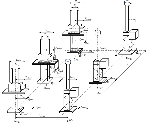
Figure 9 - Isometric representation of two elements of the equipment bay and orientation along the X‒, Y‒ and Z‒ axes
It needs to be emphasised that the Z-direction values for the equipment include the support structures. It is however possible to make the calculations more flexible by separating the equipment height dimensions from the steelwork support so as to enable varying this value as well. The support structures have been chosen so that a minimum clearance height of 2,5 m to the bottom of the equipment insulator is provied [15]. This value can also vary from country to country. In general, 2,5 m above finished ground levels are specified for high voltage.
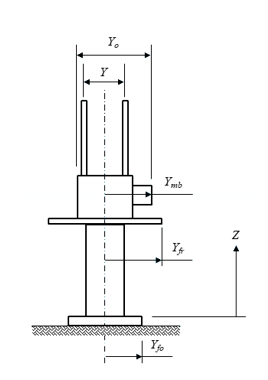
Figure 10 - Equipment bay orientation along the Y‒axis
General Quantities
There are some general quantities that need to be defined mathematically in order to complete the mathematical model, as they form an integral part in the overall analysis. Yard dimensions of width, length and height, electrical clearances of phase‒to‒phase and phase‒to‒earth, and physical dimensions of mass and tension.
Having provided a framework for assigning parameters and orientation of individual components of plant [2], the next step is to define individual bay equipment dimensions in terms of the items of plant. To prevent confusion caused by very busy drawings, dimensions are provided in multiple figures to highlight their major differences. The following images were created by the author of this paper and forms part of the study. To ensure the document's length remained reasonable, only a handful of configurations are presented.
3.1.1.1. Dimensions for Typical Circuit Breaker and Support Structures
There are several types of outdoor air-insulated circuit breakers that are mostly governed by the system voltage. Two main ones are the so-called vertical candle-stick type with a single breaking chamber (up to 300 kV) illustrated in Figure 11, and the horizontal Tee-type with multiple horizontally orientated breaking chambers (> 300 kV) shown in Figure 12.
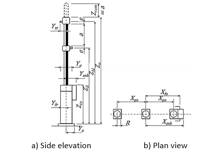
Figure 11 - Detailed Single breaking chamber dimensions
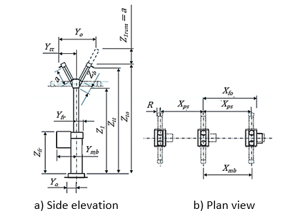
Figure 12 - Detailed Multiple breaking chamber dimensions
3.1.1.2. Dimensions for Typical Conventional Isolator and Support Structures
As with many outdoor air-insulated equipment, there are also a number of different types of conventional isolators, centre break type without and with earth-switches mounted, as illustrated in Figures 13 and 14 respectively, and double break, centre rotating post which is not illustrated.
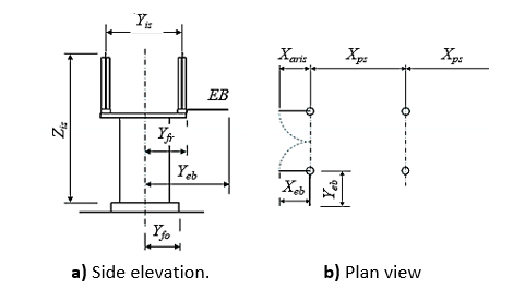
Figure 13 - Detailed isolator dimensions
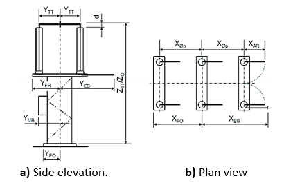
Figure 14 - Detailed isolator with earth-switch dimensions
3.1.1.3. Dimensions for Typical Current Transformer and Earth-switch Support Structures
A further two items of primary plant are provided below, in Figures 15 and 16. A current transformer which may or may not have a tank below the insulator, depending on whether it is an oil filled hair-pin type, or a sulphur hexafluoride top core type respectively. Both are represented by Figure 15. Figure 16 illustrates a free-standing earth-switch.
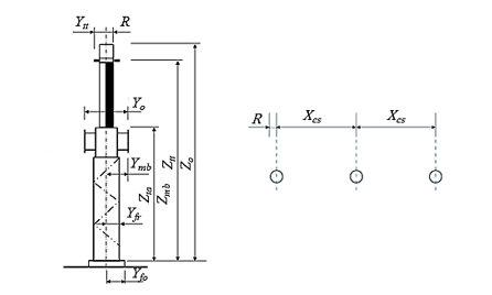
Figure 15 - Detailed Current Transformer dimensions
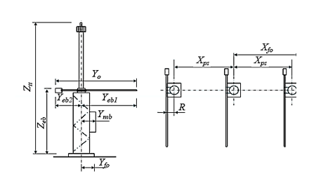
Figure 16 - Detailed Earth-switch dimensions
The minimum dimensions provided in Table 5 were suggested purely from an operations point of view for access and maintenance purposes. These values are however subjective, and may be decreased or increased according to the utility’s operations and maintenance practices. The values in Table 5 are however implemented as part of this study to illustrate the effect they have on the equipment separation dimensions.
System voltage (kV) | Minimum dimension (mm) | |||
Ya | Ya1 | Ya2 | Ya3 | |
| 6,6 ‒ 44 | ‒ | 1 000 | 1 500 | 1 000 |
| 66 | ‒ | 1 500 | 1 500 | 1 500 |
| 88, 132 | ‒ | 2 000 | 2 000 | 2 000 |
| 220, 275 | 300 | 2 500 | 2 500 | 2 500 |
| 330, 400 | 300 | 3 000 | 3 000 | 3 000 |
3.1.2. Mathematical Modelling and Dimensioning Equipment Bays ‒ Static Conditions
Since equipment level conductors are the lowest level of conductors at system voltage, they set the reference height from which all the other conductor heights are measured, all of which need to meet the statutory electrical (phase-to-earth – Ce and phase-to-phase - Cp and working clearances (Hw). There are also guidelines [16] set out detailing exposure limits for electromagnetic fields (EMF) to protect humans from adverse health effects, such as tissue heating and nerve stimulation. These are all provided in Figure 17.
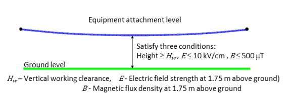
Figure 17 - First Conductor Level – Equipment Level
3.1.2.1. Minimum Spacing between Pairs of Equipment Limited by Conductor Bending Radius
When outdoor substation equipment pairs are interconnected with stranded flexible conductor, the minimum conductor bending radius of the conductor type needs to be considered. Different conductor types have different formulations for the minimum bending radius (Rc) to prevent “bird-caging” of the conductor and is defined as:
(8)
The minimum bending radius is proportional to the outer diameter (Dc) of the stranded flexible conductor [17], where kc is a unitless constant depending on the conductor type. For outdoor HV substations (6,6–420 kV):
Conductor Type | Recommended Design Value (kc) |
All Aluminium Conductor (AAC) | ≥ 12 |
All Aluminium Alloy Conductor (AAAC) | ≥ 15 |
Aluminium Conductor Steel Reinforced (ACSR) | ≥ 18 |
The connection between equipment of differing heights, as illustrated in Figure 18 a) and b), generally results in an “S” bend connection. The minimum distance between the equipment for the case is limited by the minimum conductor bending radius (Rc) indicated by (3), detailed in Figure 18b), and is provided for by [17].
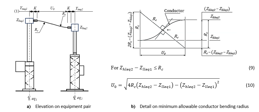
Figure 18 - Minimum distances between equipment based on minimum allowable conductor bending radius
When analysing any of the equipment pairs that are part of this study, the reverse, order but same equipment orientation should be checked. This is due to some of the equipment having protrusions, e.g., mechanism boxes, on the one side and nothing on the other that may hinder maintenance access, as shown in Figures 19 and 20. Since these have a distinct effect on the equipment separation distances, it is necessary to determine the implications on access.
Figures 19 and 20 represent two different general types of equipment (eq1 and eq2) and interconnected with either a single or multiple bundles stranded flexible conductor per phase. The aim is to provide a general idea of assigning all the essential dimensions required, relating the equipment dimensions to the electrical and, operational and maintenance clearances. The equipment dimensions would reside in an accessible and updateable data base, while the electrical clearances (Ce and Cp) are calculated according to the choice of impulse withstand level and gap factor, and the operational and maintenance access clearances can be varied in accordance with utility practices.
Table 7 provides the description and format of all the essential data base dimensions. Each of the items of equipment will have dimensions that are applicable to it, and that appear in the accompanying equations.

Table 7 - Typical Table Layout of Equipment Dimensions
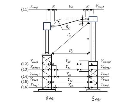
Figure 19 - eq1 and eq2 with Mechanism boxes in between
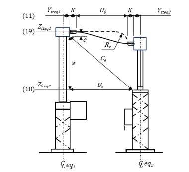
Figure 20 - eq1 and eq2 without Mechanism boxes in between
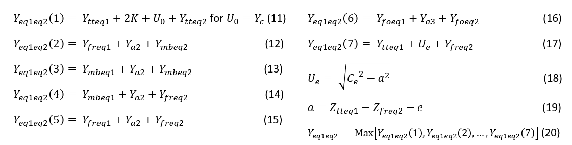
This methodology is to be applied to all the commonly occurring equipment pairs within the outdoor high voltage switching yard. Although only two sets of the two equipment combinations are discussed in detail below with illustrations, the results of the remaining typical equipment pairs found in a substation are shown in the results section.
3.1.2.2. Minimum Spacing between Current Transformers and Circuit Breaker
Table 8 provides all the essential data base dimensions for a particular 132 kV current transformer and circuit breaker. Each of the items of equipment will have dimensions that are applicable to it, and are relevant to the calculations.
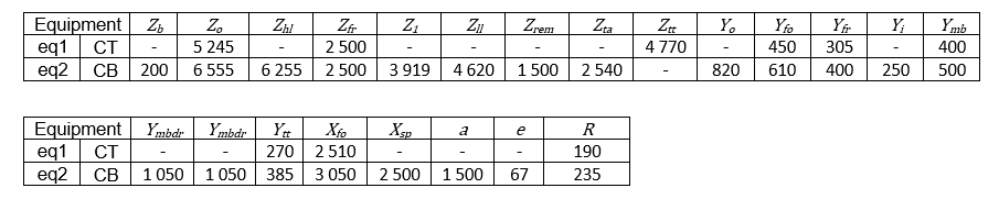
Table 8 - Dimensions relating to the chosen current transformer (eq1) and circuit breaker (eq2)
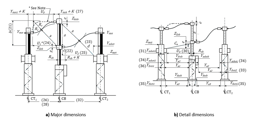
Figure 21 - Vertical single chamber circuit breaker and current transformers on one or both sides
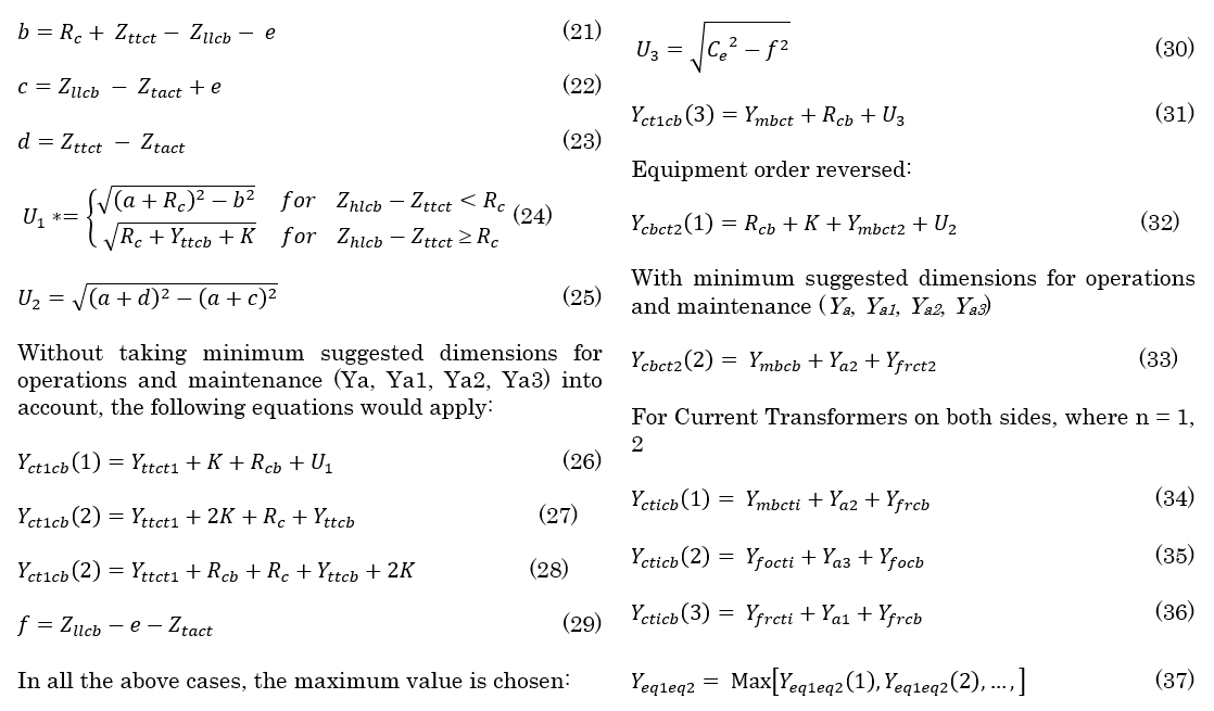
3.1.2.3. Spacing between Conventional Isolators (IS) and Circuit Breaker (CB)

Table 9 - Dimensions relating to the chosen conventional isolator (eq1) and candle-stick type circuit breaker (eq2).
The dimensions for the circuit breaker (CB) are provided under Section 3.2.1.2.
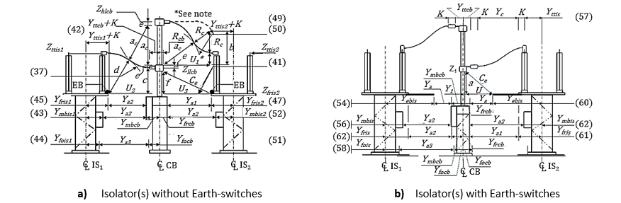
Figure 22 - Vertical single break circuit breaker with isolator(s) on one and both sides
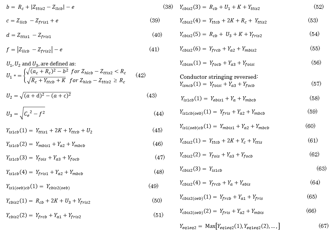

Table 10 - Dimensions relating to the chosen conventional isolator (eq1) and Tee type circuit breaker (eq2)
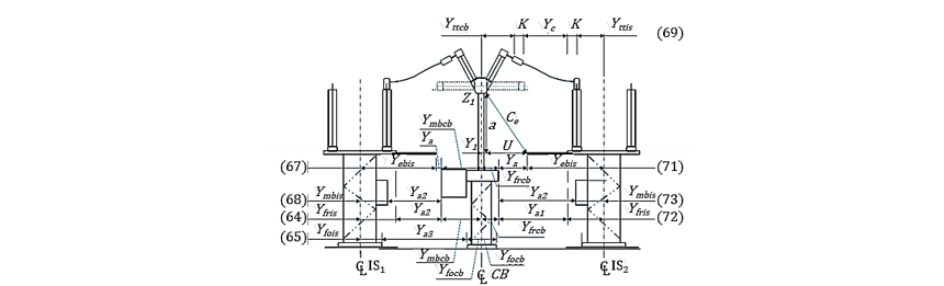
Figure 23 - Horizontal multiple break circuit breaker with isolator(s) with earthing switch(es)on one or both sides of breaker
3.2. Upper Bound Maximum Equipment Separation – Short Circuits
The short-circuit electromechanical tensile forces developed in the inter-connecting conductors, and that are transferred to the terminals of the equipment pairs is not to exceed the equipment allowable rated dynamic force. Since the behaviour of the conductors are a function of the mass per metre, two All-Aluminium Conductor (AAC) bundle configurations, commonly employed in Eskom outdoor AIS substations, were simulated. The two most prevalent in Eskom substations are Centipede (400 mm2) and Bull conductor (800 mm2). This study therefore only considers these two at the two main voltage levels that predominate, viz. 132 kV and 400 kV, with design fault levels normally set at 40 kA and 50 kA respectively. Due to the constraint on the length of the paper, only a limited number of options are presented. The remaining options follow the same procedure.
Single Centipede and Bull conductors are both used in 132 kV high voltage yards since they both satisfy the corona requirements of no corona. Three Maximum Tensile Force versus conductor length plots at a design fault level of 40 kA are provided, since all three configurations are used, viz. single Centipede (Figure 24), single Bull (Figure 25) and twin Bull (Figure 26). Twin Centipede has also been used, but has fallen out of favour since it can easily be replaced with a single Bull, and so negate the pinch force issue that is characteristic of multi-conductor bundles.
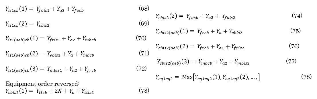
The graphs only apply to the length of the stranded flexible conductor (Yc). Therefore, to determine the overall equipment separation, all remaining equipment dimensions must be added to the conductor length (Yc), as indicated by (61) and (73).
Since each primary plant item has a maximum short-circuit dynamic rating, the smaller of the two ratings must be used to determine the related conductor length and bundle configuration. As an illustration, assuming an equipment terminal rating of 3 000 Newtons, fault current of 40 kA, and phase spacing of 3 m, the maximum conductor lengths on the three graphs are determined by drawing a horizontal line at 3 000 N (red dashed line) until it intersects the 3 m line, then projecting vertically down from this point to the abscissa, read the value on Inter-equipment conductor length.
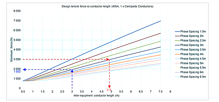
Figure 24 - Maximum tensile force vs conductor length (40 kA, 1 × Centipede conductor) (Self-generated based on [13][14])
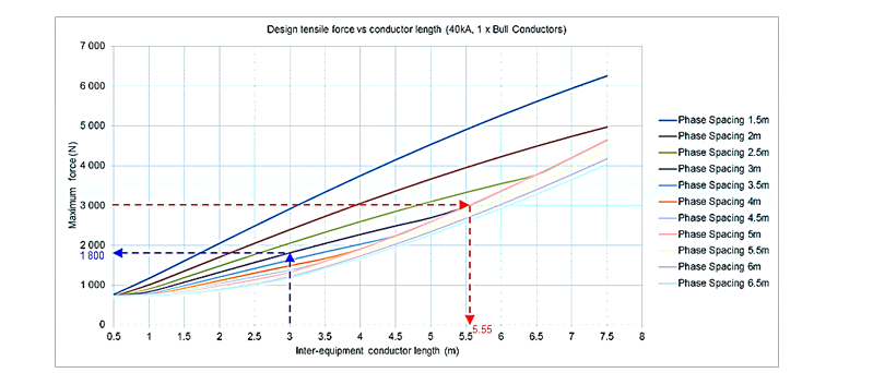
Figure 25 - Maximum tensile force vs conductor length (40 kA, 1 × Bull conductor) (Self-generated based on [13][14])
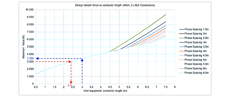
Figure 26 - Maximum tensile force vs conductor length (40 kA, 2 × Bull conductor) (Self-generated based on [13][14])
The allowable conductor lengths are as follows:
Conductor length for 1 x Centipede (Figure 24) = 4,9 m
Conductor length for 1 x Bull (Figure 25) = 5,55 m
Conductor length for 2 x Bull (Figure 26) = 2,4 m
The reason why the single Bull conductor provides better performance than a single Centipede conductor is that it is more rigid and has greater mass, therefore higher inertia. The overall motion is slightly retarded as compared to Centipede and therefore reducing the tensile force developed in the conductor. The twin Bull is impacted by the pinch force which is dominant in multi-conductor Bundles.
For substations to be corona free, only twin- and triple-Bull-conductor configurations are considered in 400 kV high-voltage yards. A Maximum Tensile Force versus conductor length plot is provided for the two-conductor configurations and shown in Figure 27.
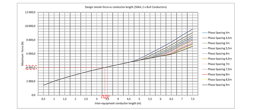
Figure 27 - Maximum tensile force vs conductor length (50 kA, 2 × Bull conductor) (Self-generated based on [13][14])
The manner in which the graph in Figure 27 is used is to draw a horizontal line from the maximum dynamic force (ordinate) that can be applied (manufacturer's guaranteed value for the item of equipment), and where it intersects the graph, to drop a line to the conductor length (abscissa). The maximum length of just the conductor [Yc (11) and (73)] that can be inserted is then given as 3,25m. The centre-to-centre distance between the pair of equipment (Yeq1eq2) is found by merely adding the rest of the dimensions in series with the conductor.
4. Results
The lower bound (minimum) values (Yeq1eq2) were determined by applying the values in the 132 kV and 400 kV equipment database to the equations under 3.1, without and with the operational and maintenance clearances. The results are provided in columns 4 and 5, respectively. The upper bound (maximum) values were determined by applying the calculations provided in [13][14] using a variety of conductor bundles as shown in columns 6 to 9. The 132 kV system dimensions were determined for a design fault level of 40 kA, with the 400 kV system design fault level at 50 kA. The maximum allowable length without exceeding the equipment's maximum dynamic rating is selected and provided in column 10. Some of the values in column 10 are shown in red text. This is to highlight the fact that due to the manufacturer’s low dynamic force rating; the upper bound value cannot meet the lower bound requirement. This therefore necessitates an alternative connecting arrangement. This is discussed under Section 5. Columns 11 to 13 are also explained in the Discussion section.
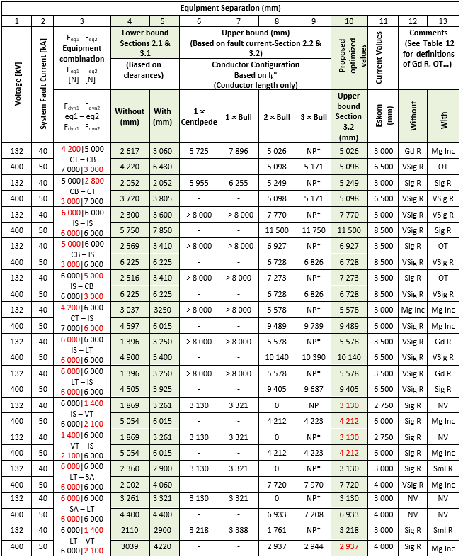
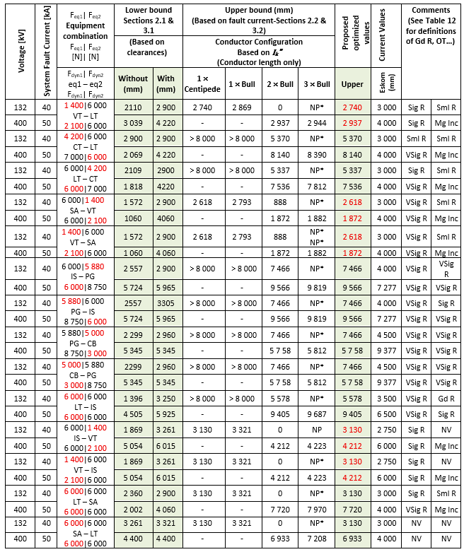
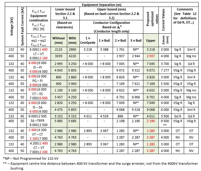
Table 11 - Categorised results as a percentage of the total simulations
5. Discussion
A total of 70 simulations were carried out, the results of which are displayed in Table 11. This covers a relatively wide range of equipment pairs for the chosen sample voltages of 132 kV and 400 kV. As a measure of the effectiveness of this study in reducing inter-equipment separation, the results are categorised by the extent of deviation from the standard values currently implemented in the South African grid and recorded in Table 12.
| Category | Abbreviation | Meaning | Without Operational Clearances | Percentage of the Options | With Operational Clearances | Percentage of the Options |
Very Significant reduction | VSig R | Reduction ³ 1 000 mm | 36 | 51,4 | 15 | 21,4 |
Significant reduction | Sig R | 500 £ Reduction < 1000 mm | 22 | 31,4 | 6 | 8,6 |
Good reduction | Gd R | 250 £ Reduction < 500 mm | 2 | 2,9 | 4 | 5,7 |
Small reduction | Sml R | 100 £ Reduction < 250 mm | 1 | 1,4 | 11 | 15,7 |
On target | OT | 0 £ Reduction < 100 mm | 2 | 2,9 | 9 | 7,1 |
Manageable increase | Mg Inc | -250 £ Increase < 0 mm | 1 | 1,4 | 19 | 27,7 |
Not viable for 2 x Bull | NV | Increase < -250 mm | 3 | 8,6 | 10 | 14,3 |
5.1. Lower Bound – Voltage Dependent Reductions
The categorisation of two sets of lower bound minimum values, considering only voltage dependent clearances and relating issues, is presented in Table 12. The first set does not take the suggested operating and maintenance clearances (Ya, Ya1, Ya2, Ya3) into account, but does fulfil the safety clearance aspects. The second set does include these clearances, which are purely for access purposes. Since these clearance values are somewhat subjective and highly dependent on the utility's operating and maintenance practices, they could potentially be reduced by employing a different maintenance practice.
It is evident from the first set of values, that 90% of the cases show definite reduction in the equipment spatial separation, ranging from a small reduction (³ 100 mm) to a very significant reduction (+52% ³ 1 000 mm). Only a single case required an insignificant increase (£ 250 mm) in separation, which could possibly be accommodated with a small modification. As for the three cases classified under not viable (NV), these actually refer to voltage sensitive equipment such as voltage transformers and surge arresters that do not have to be within the current path. The connection to them can be made by simply teeing back to them as illustrated in Figures 28 and 29.
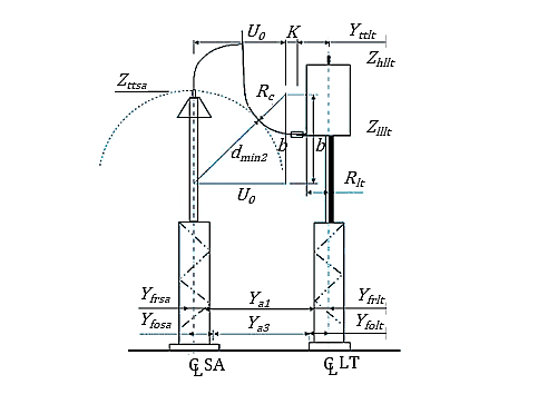
Figure 28 - Surge arrester and line trap
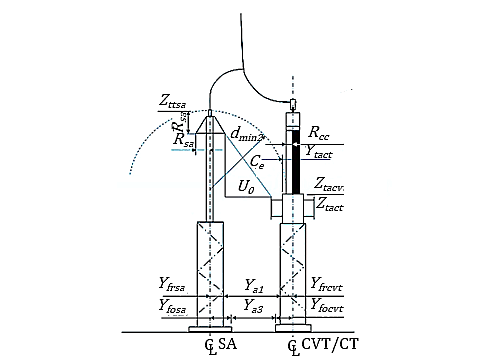
Figure 29 - Surge arrester and voltage transformer
The second set of values in Table 6 show a similar trend as the first, only that the additional separation for access places a number of cases beyond the current standard values. Under these requirements, the number of cases that show definite reduction in the equipment spatial separation reduces to +52%, also ranging from a small reduction (³ 100 mm) to a very significant reduction (+22% ³ 1 000 mm). Nineteen cases required an insignificant increase (£ 250 mm) in separation. Ten cases classified not viable (NV) refer to voltage sensitive equipment such as voltage transformers and surge arresters that as before do not have to be within the current path. All the remainder cases require an increase of less than 800 mm, most around 250 mm. These are all manageable with some modification to support structures or perhaps choosing a different product, it would be possible to reduce this to within the standard separation.
5.2. Upper Bound – Fault Current Dependant Separation
As discussed under Section 2.2, the maximum spatial separation of the equipment pair is limited by the equipment terminal dynamic force rating. In all sixteen (16) cases where the maximum spatial separation limitation due to fault current cannot be met (shown in Table 12 in red text), it is due to the low dynamic rating of the voltage transformer terminals at both voltage levels, i.e., 132 kV and 400 kV. The maximum upper bound separation is less than the required separation for voltage purposes. However, the voltage transformer and surge arrester can be moved out of the bay current path, repositioning these with tee-off connections. Since there is no requirement for meeting bay load current, the number of conductors required for the tee-off connection, can be dramatically reduced to a single conductor, providing the no-corona requirement is met. It has been demonstrated in Figure 6 that multiple sub-conductors per phase, present the largest problem with respect to tensile forces. If a single conductor can be used, it is best option. At 132 kV, a single centipede can be used, while at 400 kV the minimum is twin Bull is required. This will then completely solve that problem, and the combination will be out of the fault current path for all of these cases.
As a last noteworthy observation, it must be borne in mind that equipment manufacturers produce equipment of the same type, with differing dimensions. Therefore, when utilities specify equipment parameters, it may require additional information pertaining to the maximum allowable dimensions to be included in the documentation. An additional specification may be that the mechanism boxes should be so located that they do not impede access between equipment pairs in the Y-direction, and rather be located in the X-direction.
6. Conclusion
From the foregoing, the study has proved that the proposed methodology has the potential to be a very effective means for creating a new set of standard designs in terms of equipment spatial separation, providing all the parameters as described in Section 2, and equipment dimensioning as described in Section 3, are made available. In addition, if the voltage sensitive equipment, viz. surge arresters and voltage transformers are moved out of the current path, then virtually all the current standard dimensions can be reduced, and still meet the operational safety requirements. The study in respect of reducing inter-equipment has proved to be a very successful one.
Further study will deal with the design of the accompanying supporting ‘superstructure’, made up of columns and beams in relation to the equipment separation distances determined in this paper.
Acknowledgment
I wish to express my sincere gratitude and appreciation to my co-author for the guidance and suggestions in compiling this paper.
References
- IEC 60071-1, "Insulation co-ordination - Part 1: Definitions, principles and rules", 2019.
- Groenewald AJS., Khan M. F., “Modernizing Outdoor Substation Design by the Novel Application of Probabilistic Design Principles”, Under review IEEE Access, 2026.
- “Lightning Protection Guide” (3rd updated edition) by DEHN, Chapter on "Surge Arrester Behaviour and Air Gap Coordination"
- IEC 60099-4, " Metal-oxide surge arresters without gaps for a.c. systems", 2014.
- IEEE Standard C62.11-2005 (Revision of C62.11-1997, “Standard for Metal-Oxide Surge Arresters for AC Power Circuits (>1 kV)”.
- JP Schutte, "Voltage uprating of existing high voltage substations when transient voltage stress and available withstand strength are coordinated", MSc Dissertation, June 2017. Presented at 2018 Busisipho Siyobi and Mischka Moosa, "100 years of Eskom: How did we get here?", Publication by Good Governance Africa (GGA), Aug 23, 2022.
- Naicker E., Groenewald AJS., Moodley Y. " Design Considerations in the Uprating of Substation Nominal Voltage from 400kV to 500KV in the Eskom Network". Presented at Southern African Cigre Conference, June 2015
- Montgomery, D.C.; Runger, G.C., “Applied Statistics and Probability for Engineers”, Wiley, latest edition. Appendix: Standard Normal Distribution Table.
- Le Roy, J. & Gallet, F., “Electrical Breakdown in Air at High Voltages”, 1961.
- Le Roy-Gallet, H., “La caractéristique tension-courant des parafoudres en oxyde de zinc”, Comptes Rendus de l'Académie des Sciences (French Academy of Sciences Proceedings), 1965.
- Moosa M. and Siyobi B, “100 years of Eskom: How did we get here?”, Good Governance Africa Publication, August 2022.
- Chetty V., Davidson I. E., Sharma G., “The Recent Trend of Increasing Fault Current Levels and Mitigation Measures”, 2021.
- IEC 60865-1, "Mechanical and thermal effects of short-circuit currents in outdoor substations - Part 1: Definitions, principles and rules", 2019.
- IEEE Std 605-2010, “IEEE Guide for Bus Design in Air Insulated Substations”.
- IEC 61936-1 / DIN EN 61936-1 (VDE 0101-1), “Power installations exceeding 1 kV AC – Part 1: General requirements”, CENELEC, Edition 3.0, September 2021
- HEALTH PHYS 118(5): 483–524; 2020, “ICNIRP Guidelines for Limiting Exposure to Electromagnetic Fields (up to 300 GHz)”
- IEC 61089, “Round wire concentric lay overhead electrical stranded conductors”, 2022
Appendix
10.1. Dimensions for Typical Electromagnetic and Capacitor Voltage Transformer and Support Structures
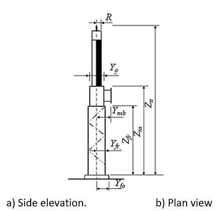
Figure 30 - Electromagnetic voltage transformer
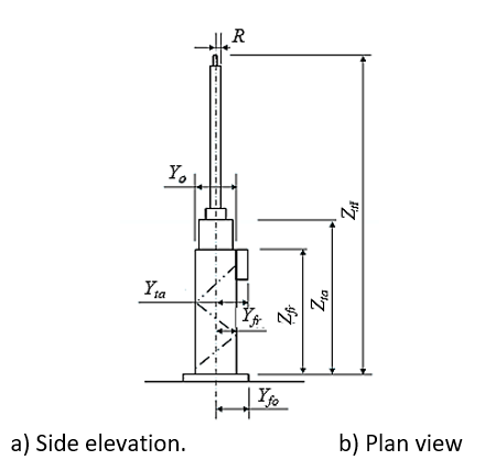
Figure 31 - Coupling capacitor or capacitor voltage transformer
10.2. Dimensions for Typical Post Insulator, Pantograph Isolator and Support Structures
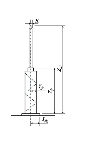
Figure 32 - Pantograph Isolator
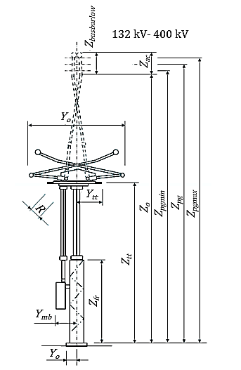
Figure 33 - Pantograph Isolator
10.3. Dimensions for Typical Post Insulator, Line Trap, Surge Arrester and Support Structures
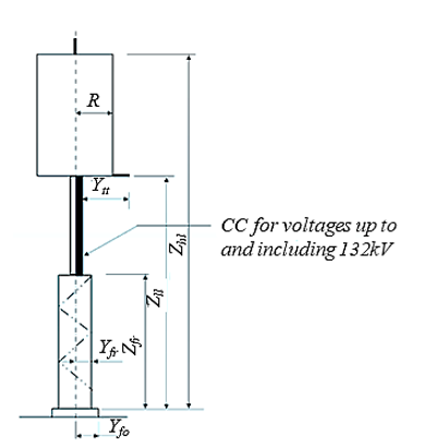
Figure 34 - Line Trap
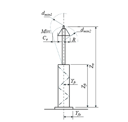
Figure 35 - Surge Arrester
(79)
The minimum distance (dmin [mm]) of an earthed or a live part to a surge arrester shall be 11 × the surge arrester rated voltage (Ur [kV])” refers to a rule-of-thumb air-clearance requirement used in high-voltage substation design to ensure that the surge arrester effectively protects the connected equipment under lightning impulse conditions [1][4][5]. This means that the air gap between the live conductor and the surge arrester terminal (or earth reference) must be sufficiently large so that:
- The air insulation does not flash over before the arrester operates, and
- The arrester remains the preferred discharge path for overvoltage energy.
- The constant 11 mm/kV is an empirical factor derived from:
- Standard lightning impulse withstand characteristics of air
- Typical arrester protective levels
Coordination margins according to insulation coordination practice
10.4. Dimensions for Typical Power Transformers
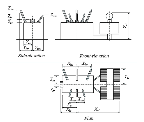
Figure 36 - Transformer
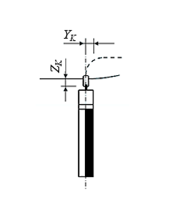
Figure 37 - Equipment to Conductor Clamp dimensions
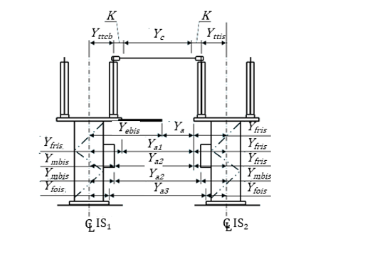
Figure 38 - Two isolators (one with earth‒switch)
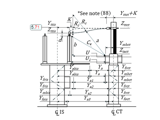
Figure 39 - Isolator with earth‒switch and current transformer
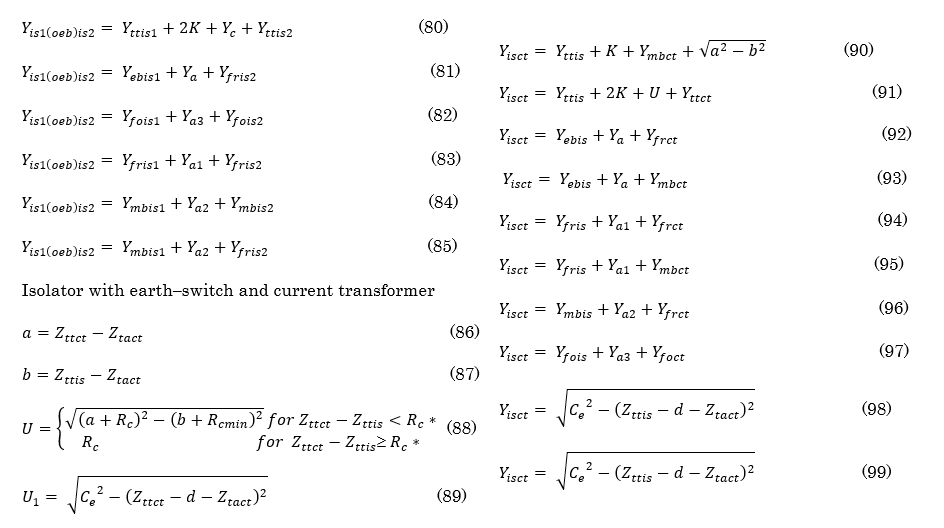
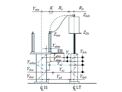
Figure 40 - Isolator with earthing switch and line trap
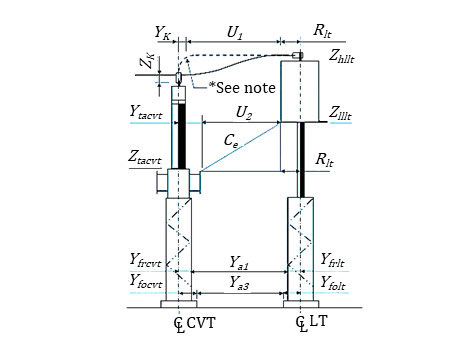
Figure 41 - Voltage transformer and line trap
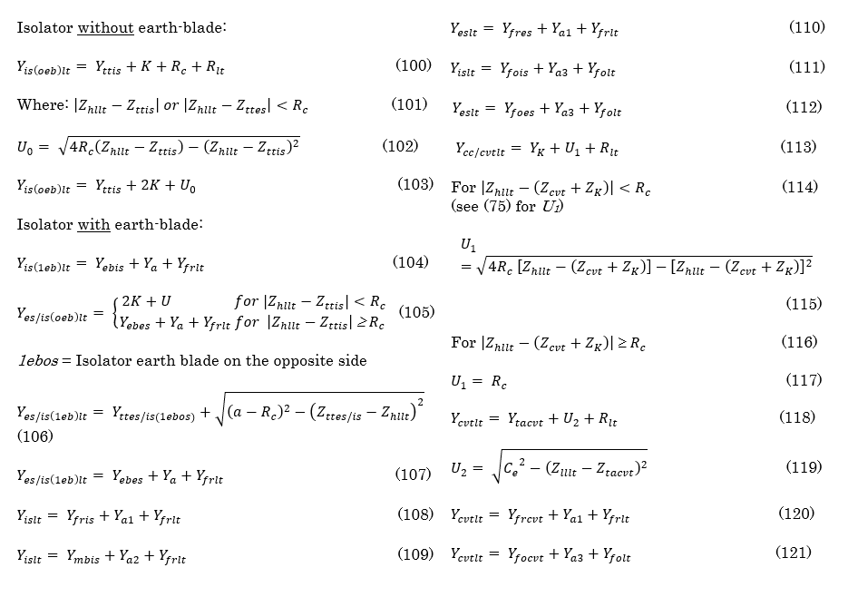
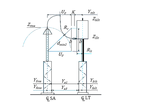
Figure 42 - Surge arrester and line trap
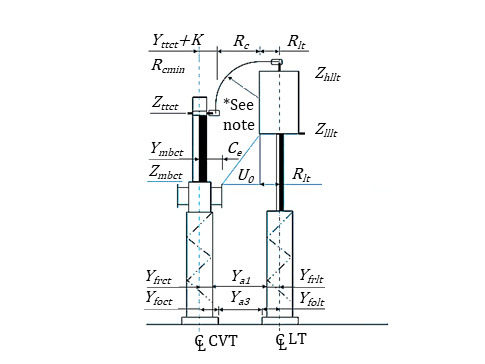
Figure 43 - Current transformer and line trap
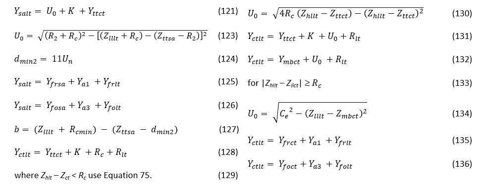
Surge arrester and capacitor voltage transformer/current transformer
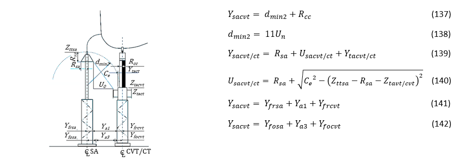
Figure 44 - Surge arrester and capacitor voltage transformer/current transformer
Conventional Isolator and Pantograph Isolator/Pantograph Isolator and Circuit Breaker
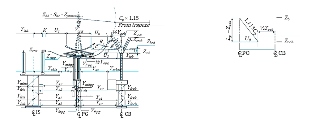
Isolator and pantograph and, pantograph and circuit breaker in a series connection
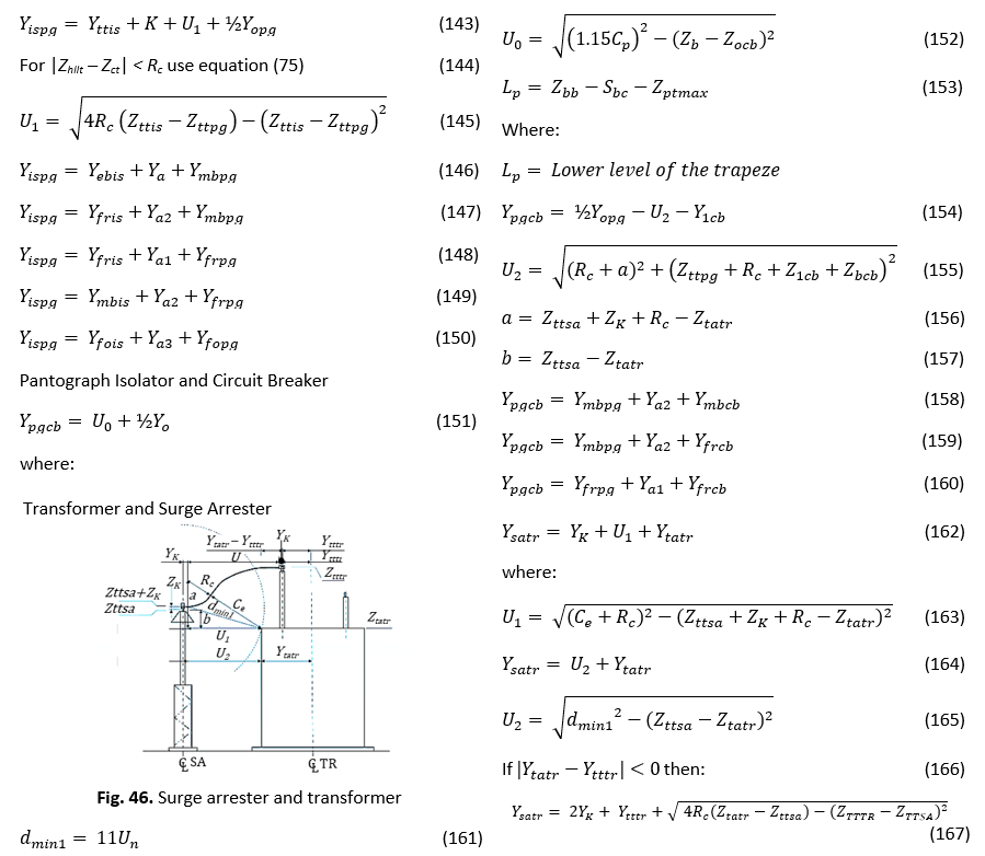
Conventional Isolator and Pantograph Isolator
The same two conductor configurations were simulated for a fault level of 63 kA only for comparative purposes.
The resulting plots are provided in Figures 47 and 48.
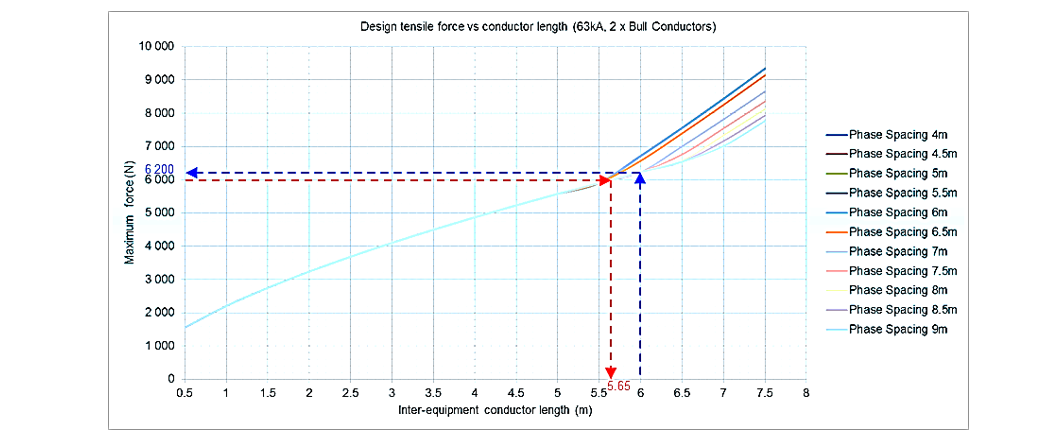
Figure 47 - Maximum tensile force vs conductor length (63 kA, 2 × Bull conductor)
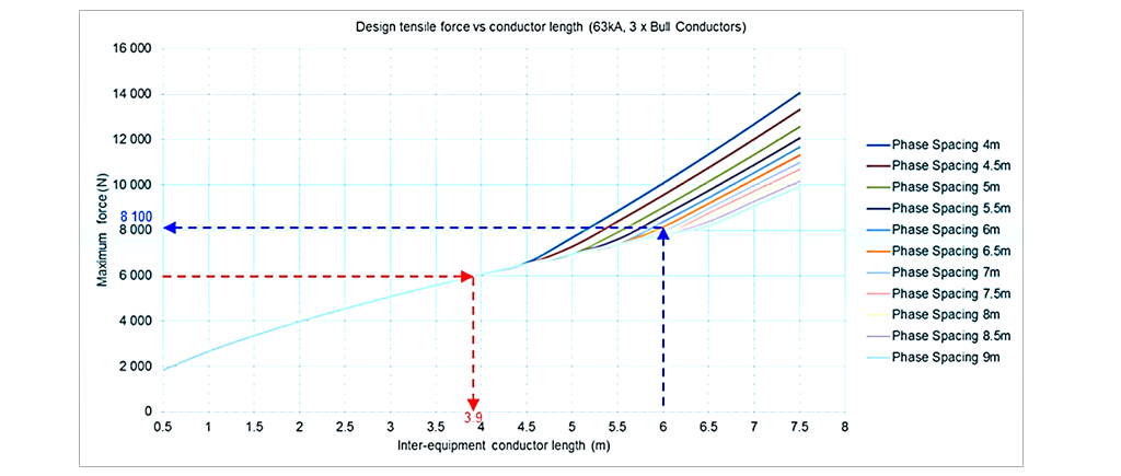
Figure 48 - Maximum tensile force vs conductor length (63 kA, 3 × Bull conductor)
Biographies
Abraham (Braam) Johannes Smit Groenewald
Braam received the B.Sc. and M.Sc. degrees in electrical engineering from the University of KwaZulu-Natal (UKZN), South Africa, in 1984 and 2008, respectively. Braam worked for the South African National Power Utility, Eskom, as a substation design engineer, where he remained until he retired in 2022 having reached the position of Corporate Specialist, Substation Design department. He has experience in all voltages from 3,3 kV through to, and including 800 kV. Braam is still active as a substation design consultant, consulting to various local and overseas substation design houses. His interests remain with discovering new techniques in substation design to assist design engineers in arriving at an optimised substation design solution, and solving engineering problems with sound mathematical reasoning. He is a registered Professional Engineer with the Engineering Council of South Africa (ECSA) and a fellow of South African Institute of Electrical Engineers (SAIEE). He also holds a BCom from the University of South Africa.
Mohamed Fayaz Khan (Senior Member, IEEE)
Mohamed received the B.Sc., M.Sc., and Ph.D. degrees in electrical engineering from the University of KwaZulu-Natal (UKZN), South Africa, in 2000, 2003, and 2020, respectively. He is currently employed as a Senior Lecturer with the Discipline of Electrical Engineering, UKZN and serves as the co-director for the UKZN Centre for Power and Energy Systems (CPES). With over 20 years of power utility experience prior to becoming an academic, he has a passion for power system innovations and developments that are implementable and contribute positively to the industry and society. He is a registered Professional Engineer with the Engineering Council of South Africa (ECSA) and a fellow of South African Institute of Electrical Engineers (SAIEE)