Technical Aspects of Grounding Grid Design Calculation for FACTS and HVDC Projects
Authors
Basem Mohammad ALSUHAIBANI, Ahmed Mohamed IBRAHIM, Amitabha CHAKRABARTI, Ahmed E. ELGEBALY
FACTS Projects, Engineering and Design Department, Saudi Electricity Company, Riyadh, Saudi Arabia

This paper addresses the technical complexities involved in designing grounding systems for Flexible AC Transmission Systems (FACTS) and High Voltage Direct Current (HVDC) substations, with a focus on installations in high-resistivity regions such as Saudi Arabia. Ground Potential Rise (GPR), a critical safety parameter, is significantly influenced by soil resistivity, fault current behavior, and grounding grid configuration. The study evaluates the various grounding design methodologies aligned with IEEE and Saudi Electricity Company (SEC) standards. Through detailed analysis of STATCOM and HVDC projects, the paper highlights the importance of advanced modeling, iterative safety assessments, and the use of mitigation strategies such as Ground Enhancement Materials (GEM), grounding grid reconfiguration, and inter-substation interconnection. The findings offer a comprehensive framework for achieving safe, reliable, and cost-effective grounding solutions in challenging environments.
Keywords
Grounding System Design, Ground Potential Rise (GPR), Ground Enhancement Materials (GEM), Grounding Grid Reconfiguration1. Introduction
In modern power systems particularly those incorporating Flexible AC Transmission Systems (FACTS) and High Voltage Direct Current (HVDC) technologies the design of a reliable grounding system is paramount for ensuring operational safety and equipment protection [1]. Grounding systems serve as the primary defense against electrical hazards arising from fault conditions, and their effectiveness is evaluated through parameters such as Touch Voltage, Step Voltage, and Ground Potential Rise (GPR) [2].
Touch voltage refers to the potential difference between a grounded structure and the surface where a person may be standing, while step voltage is the voltage difference experienced across a one-meter span on the ground surface [3]. GPR, defined as the product of maximum grid current and grid resistance, represents the maximum voltage a substation ground grid may attain relative to remote earth during fault conditions. These voltages persist until the protection system operates and clears the fault, posing risks to both personnel and equipment [4].
The primary objectives of a grounding system are to safely transfer electric currents into the earth under both normal and fault conditions, without exceeding equipment limits or compromising service continuity. A well-designed grounding system minimizes the risk of critical electric shock to individuals in the vicinity of grounded structures and ensures the integrity of control and communication equipment [5].
Substations with grounded wye transformers supplying distribution networks are particularly vulnerable during ground faults, as fault currents flow through the earth, causing GPR within and around the substation. If the grounding resistance is high, the resulting GPR can be substantial, leading to elevated step and touch voltages, damage to control cables, and threats to operator safety. To mitigate these risks, grounding systems must effectively interconnect all metallic components and maintain low impedance paths for fault currents [6].
In regions like Saudi Arabia, where geological conditions often result in high soil resistivity, maintaining GPR within the permissible threshold of 5000 V as specified by the Saudi Electricity Company and IEEE Std. 367 [7] poses significant engineering challenges. High resistivity impairs fault current dissipation, necessitating advanced mitigation strategies such as enlarging the grounding grid, increasing the length of buried conductors, forming deep ground wells, and using ground enhancement materials (GEM) [8].
STATCOM and HVDC substations introduce unique grounding challenges due to their sensitivity to electromagnetic interference and the presence of fast-switching converters and high-frequency components. These systems can generate transient overvoltages and harmonic disturbances, requiring grounding designs that incorporate shielding, equipotential bonding, and considerations for bidirectional current flow and DC fault conditions [9].
This paper investigates the technical aspects of grounding grid design for STATCOM and HVDC substations, emphasizing the influence of soil characteristics, fault current behavior, and grounding grid configuration on GPR. It also explores the limitations of conventional safety measures and the necessity of integrating advanced mitigation strategies such as grounding grid reconfiguration, interconnection with nearby substations, and the use of GEM to achieve compliance with safety standards. Through a detailed analysis of real-world STATCOM projects in Saudi Arabia, this study aims to establish an optimized methodology for grounding grid design that balances technical performance, cost efficiency, and environmental sustainability.
2. Grounding system considerations for FACTS and HVDC projects
The grounding system design for FACTS and HVDC substations requires a more rigorous and specialized approach compared to conventional AC substations, due to the unique operational characteristics and sensitivity of these technologies. In particular, Static Synchronous Compensators (STATCOM) and HVDC systems introduce high-frequency switching, large fault currents, and complex electromagnetic environments that demand enhanced grounding strategies to ensure both safety and system reliability.
2.1. Grounding Requirements for STATCOM Installations
STATCOM substations, as part of the FACTS family, are equipped with power electronic converters as a voltage source converters (VSC) that generate high-frequency transients and harmonic currents. These conditions necessitate grounding systems that not only meet conventional safety standards but also mitigate electromagnetic interference (EMI) and prevent circulating currents.
To address these challenges, STATCOM grounding systems are typically designed using a radial configuration that avoids forming closed loops, which could otherwise allow induced high frequency currents to flow. This is particularly important near air-core reactors and metallic fences, where magnetic coupling can lead to unwanted current paths. The grounding system must also maintain adequate clearance from sensitive components and be interconnected with the main substation grounding grid in a manner that preserves electrical continuity without compromising isolation.
Furthermore, the grounding design must comply with both Saudi Electricity Company (SEC) standards and IEEE guidelines [10], ensuring that touch and step voltages remain within safe limits. Equipment grounding must follow manufacturer-specific recommendations, and any new grounding installations such as those for new SVC bays must be carefully integrated to avoid interference with existing systems. Contractors are required to submit detailed grounding plans and calculations for review, ensuring that all safety and performance criteria are met.
2.2. Grounding Considerations for HVDC Systems
HVDC systems present a distinct set of grounding challenges, particularly during ground return mode operation. In this mode, large magnitudes of direct current often in the range of thousands of amperes are injected into the earth through dedicated ground electrodes. This results in a significant Ground Potential Rise (GPR) around the electrode site, which can propagate through the soil and affect remote substations and infrastructure.
The behavior of GPR in HVDC systems is influenced by the geo-electrical structure of the soil, including both surface and deep-layer resistivity. Variations in Earth Surface Potentials (ESPs) between substations can lead to neutral current flow through grounding transformers and transmission lines, potentially causing interference and equipment stress. These effects are particularly pronounced in regions with complex three-dimensional soil resistivity profiles, which are often overlooked in conventional grounding analyses.
To mitigate these risks, HVDC grounding systems must be designed with a comprehensive understanding of soil conductivity, fault current paths, and induced voltage behavior. Grounding of HVDC equipment must strictly adhere to manufacturer specifications, and the design must account for both AC and DC fault scenarios. Additionally, shielding effects from overhead ground wires and cable sheaths should be considered to reduce the impact of induced voltages.
2.3. Design Procedure of grounding system
The design of a grounding system for FACTS and HVDC substations follows a structured sequence of
steps to ensure compliance with safety standards and operational reliability. The process is illustrated in
the block diagram of Figure 1 and is described as follows:
a. General Site Assessment:
Begin with a general location map of the substation area to be grounded. Conduct a soil resistivity test using the Wenner four-pin method [11], as outlined in IEEE Std. 81 [12], to characterize the subsurface electrical properties.
b. Conductor Sizing:
Determine the minimum conductor size using Equation 1, ensuring it can withstand thermal and mechanical stresses during fault conditions.
(1)
Where:
If = Symmetrical ground fault current in “kA”. (For National Grid Saudi Arabia system this value shall
be breaker rated short circuit current)
A = Conductor cross section in “mm²”
Tm = Fusing temperature in (maximum allowable temperature) in “°C”
Ta = Ambient temperature in “°C” = Thermal coefficient of resistivity of conductor material at reference temperature Tr in “1 / ºC”
= Resistivity of the ground conductor at referenced temperature Tr in “micro-ohms cm”
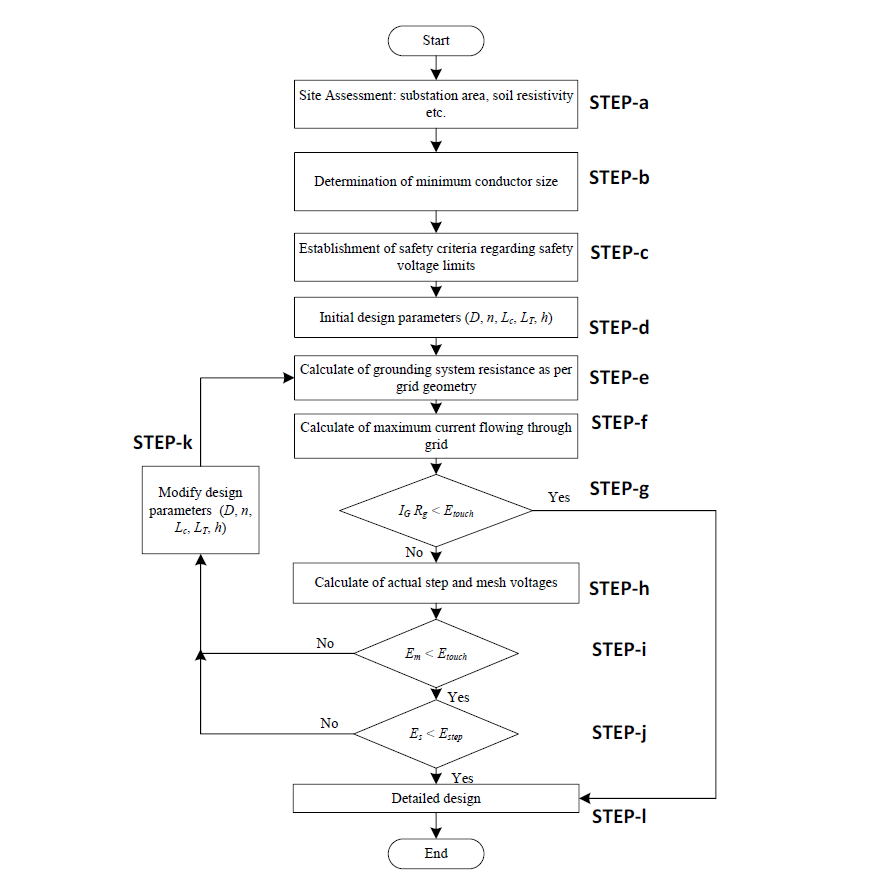
Figure 1 - Block diagram for grounding grid design
tc = Maximum possible clearing time. This shall be taken as “1.0 (one) second”.
TCAP = Thermal capacity factor from Table 10-1 in “J/cm³.°C”
Where
Tr = reference temperature for material constants in “°C” = thermal coefficient of resistivity of conductor material at “0 °C in 1/ “°C”
Note that and
are both to be found for the same reference temperature
c. Safety Voltage Limits:
Calculate the tolerable step and touch voltages using Equations 2 and 3, based on IEEE Std. 80 guidelines and site-specific parameters such as soil resistivity and fault duration.
(2)
(3)
A typical human body exhibits an electrical resistance of approximately 1000 ohms, whether the current path is from hand to both feet, between the hands, or from one foot to the other. Cs represents a correction factor applied to adjust the nominal resistivity of the surface layer. When no protective layer is used meaning the surface and soil resistivities are equal Cs is set to 1. If a protective layer with higher resistivity than the surrounding soil is present, Cs takes a value less than 1.
d. Preliminary Grid Layout:
Develop a preliminary grounding grid layout, including a perimeter conductor loop and cross conductors to ensure uniform potential distribution. Estimate conductor spacing and ground rod locations based on the expected grid current (IG) and the area to be grounded.
e. Grounding Resistance Calculation:
Compute the grounding resistance (Rg). For uniform soil, use Equation 4. For two-layer or multi-layer soil profiles, employ computer-based modeling tools to simulate the grounding system and accurately determine Rg.
(4)
where
Rg: Represents the resistance of the substation grounding system, measured in ohms (Ω). :Denotes the average resistivity of the soil, expressed in ohm-meters (Ω·m).
A: Refers to the total surface area covered by the grounding grid, measured in square meters (m²).
LT: Indicates the cumulative length of all buried conductors in meters (m). In configurations that include both grid conductors and ground rods, LT accounts for the combined length of both components.
h: Specifies the depth at which the grounding grid is installed, in meters, excluding any asphalt or surface covering. This depth is used in calculations even when part of the grid is located beneath structures such as control buildings.
f. Grid Current Estimation:
Determine the maximum grid current (IG) using Equation 5, considering the worst-case fault scenario and system configuration.
(5)
IG: The peak current flowing through the grounding grid, measured in amperes (A).
Df: The decrement factor applied over the total fault duration (tf, in seconds), which accounts for the DC offset in the fault current due to its asymmetrical nature. This factor is influenced by the system’s X/R ratio and the duration of the fault. For the National Grid in Saudi Arabia, where the minimum shock duration is 0.5 seconds, Df is typically taken as 1.
Ig: The root mean square (RMS) value of the symmetrical grid current, in amperes (A). It represents the portion of the symmetrical ground fault current that flows from the grounding grid into the surrounding earth. It is calculated by multiplying current division factor by breaker short circuit rating [12].
g. GPR Evaluation:
Evaluate the Ground Potential Rise (GPR) using Equation 6. If the GPR is below the tolerable touch voltage, the design is considered safe, and only minor additions for equipment grounding are required.
(6)
where IG is the maximum Grid Current in A and Rg is the grounding resistance in Ω
h. Voltage Analysis:
If the GPR exceeds the tolerable touch voltage, calculate the mesh and step voltages using Equations (7) to assess the safety of the design.
(7)
: Represents the resistivity of the soil, measured in Ω·m, which influences the performance of the grounding system.
Km: A spacing coefficient used in the calculation of mesh voltage, reflecting the layout and separation of conductors within the grounding grid.
Ki: A correction factor that adjusts for the specific geometry of the grounding grid, ensuring accurate voltage and resistance estimations.
LM: The total effective length of conductors buried in the ground, measured in meters which contributes to the overall grounding performance.
(8)
Ls is the effective buried conductor length in meter and Ks maximum step voltage factor.
i. Mesh Voltage Check:
If the calculated mesh voltage is below the tolerable touch voltage, the design may be accepted. Otherwise, proceed to revise the design as per step (k).
j. Final Safety Check:
If both touch and step voltages are within tolerable limits, finalize the design with only minor refinements for equipment access. If not, proceed to step (k).
k. Design Revisions:
Revise the grounding grid design if tolerable limits are exceeded. Revisions may include reducing conductor spacing, adding ground rods, or reconfiguring the grid layout.
l. Final Adjustments:
Once safety criteria are met, add any additional conductors or ground rods required for specific equipment (e.g., surge arresters, transformer neutrals). Review the final design to eliminate hazards from transferred potential and ensure compliance with all applicable standards. The previous design steps are applied to design the grounding grid. The following section discusses the causes of GPR violation to be coincided with the design procedure that fulfils the proper design.
3. Causes of GPR high values and their impact
High values of GPR represent a critical concern in the grounding design of FACTS substations, particularly in environments characterized by high soil resistivity. GPR, defined as the product of maximum grid current and ground resistance, reflects the voltage elevation of a substation’s grounding system relative to remote earth during fault conditions. While IEEE Std. 80 and IEEE 367 establish permissible thresholds to safeguard personnel and equipment typically not exceeding 5000 V achieving compliance in high-resistivity terrains poses significant engineering challenges.
In regions such as Saudi Arabia, geological formations often consist of dry, rocky, or layered soils with poor conductivity. These conditions hinder the dissipation of fault currents into the earth, resulting in elevated ground resistance and, consequently, increased GPR levels. The complexity is further compounded by the presence of multi-layer soil structures, where upper layers exhibit high resistivity while deeper strata may offer improved conductivity. Conventional grounding analyses, which often assume uniform soil profiles, fail to capture the nuanced behavior of such stratified systems, leading to underestimation of GPR risks.
Accurate modeling of soil resistivity is essential for predicting GPR behavior. Techniques such as Wenner’s four-pin method and computer-aided simulations based on IEEE Std. 80 allow engineers to construct multi-layer soil models that reflect real-world conditions [13]. These models are particularly valuable in regions with non-uniform or stratified soil, where surface measurements alone may underestimate grounding challenges.
Compliance with IEEE 80 and SEC standards is not only a regulatory requirement but also a critical design objective to ensure that GPR remains within safe operational thresholds under worst-case fault conditions. Elevated GPR levels can induce hazardous touch and step voltages, compromise insulation integrity, and disrupt the operation of sensitive control and communication equipment. In interconnected substations, GPR can propagate through grounding transformers and cable sheaths, introducing transferred potentials that affect remote installations. These effects are particularly pronounced in FACTS substations, where high-frequency switching and power electronic components are highly susceptible to electromagnetic disturbances.
To mitigate these risks, grounding designs must incorporate advanced modeling techniques that account for three-dimensional soil resistivity profiles and fault current behavior. Strategies such as deep-driven ground electrodes, interconnection with adjacent substations [15], and the use of ground enhancement materials (GEM) are essential for reducing effective ground resistance and maintaining GPR within acceptable limits. Furthermore, site-specific soil investigations and computer-aided simulations are indispensable tools for ensuring that grounding systems meet both safety and performance criteria under diverse geological conditions.
4. Practical solutions for GPR mitigations
Addressing Ground Potential Rise (GPR) violations in FACTS substations requires a combination of engineering strategies that enhance the grounding system’s ability to dissipate fault currents effectively, particularly in high-resistivity soils. This section outlines practical mitigation techniques that have been successfully implemented in ±300 MVAR STATCOM projects in Saudi Arabia, where GPR levels initially exceeded the permissible threshold of 5000 V. The grounding system design calculations are performed using the CYMGRD software [14], version 6.3.
4.1. Grounding Grid Reconfiguration
One of the most direct methods for reducing GPR is the reconfiguration of the grounding grid. This involves increasing the number and length of ground rods, decreasing the spacing between horizontal conductors, and applying a low-resistivity backfilling layer. These modifications enhance the contact area with the soil and reduce the overall ground resistance. However, even with aggressive grid densification such as reducing conductor spacing to 3×3 meters and increasing rod count GPR may still remain above acceptable limits in high-resistivity environments.
4.2. Interconnection with Nearby Substation Grounding Grids
Another effective strategy is the electrical interconnection of the FACTS substation grounding grid with that of a nearby AC substation. This approach increases the effective grounding area and provides additional current dissipation paths, thereby reducing the overall GPR. In practice, this method has demonstrated significant improvements, lowering GPR values by more than 50% in some cases. However, it may still fall short of compliance if soil resistivity remains high or if the interconnected grid is not sufficiently robust.
4.3. Application of Ground Enhancement Materials (GEM)
Ground Enhancement Materials (GEM) offer a high-performance solution for reducing soil resistivity in localized areas. When applied around ground rods or in trenches, GEM significantly improves the conductivity of the surrounding soil, thereby lowering the effective ground resistance. In one STATCOM project scenario, the use of GEM with a resistivity of 0.02 Ω·m reduced GPR to below 600 V well within the safety threshold. Despite its effectiveness, GEM introduces additional considerations, including higher material costs, environmental impact, and potential degradation over the project’s lifetime.
4.4. Comparative Analysis of Mitigation Scenarios
Table 1 summarizes the design parameters and performance outcomes for four grounding grid configurations applied in a STATCOM project. The scenarios demonstrate the progressive impact of each mitigation strategy on GPR reduction:
Scenario 1: Baseline design with 7×7 m spacing and standard rods GPR exceeds 24,000 V.
Scenario 2: Grid densification and soil backfilling GPR reduced to ~20,000 V.
Scenario 3: Interconnection with nearby substation GPR reduced to ~9,800 V.
Scenario 4: GEM application GPR reduced to ~580 V, achieving full compliance.
While GEM provides the most substantial reduction, the optimal solution often involves a hybrid approach that balances technical performance, cost, and environmental sustainability.
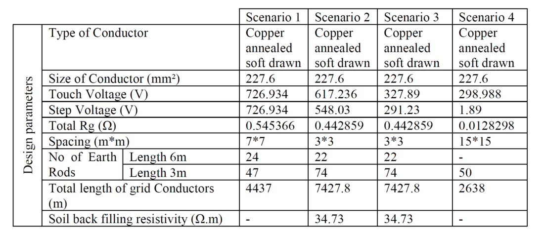
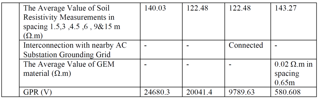
Table 1 - Design parameters of STATCOM station grounding grid scenarios
Potential threshold for each scenario is illustrated in Figure 2.
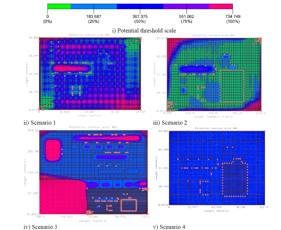
Figure 2 - Potential threshold for various scenarios
5. Conclusions
The design of grounding systems for FACTS and HVDC substations presents unique technical challenges, particularly in regions with high soil resistivity such as Saudi Arabia. Ground Potential Rise (GPR), a critical safety and performance parameter, is significantly influenced by soil characteristics, fault current behavior, and grounding grid configuration. This paper has demonstrated that conventional grounding approaches are often insufficient to maintain GPR within the permissible threshold of 5000 V, especially in complex geological environments.
Through a detailed examination of STATCOM and HVDC installations, the study highlighted the limitations of traditional design practices and emphasized the need for advanced modeling techniques and mitigation strategies. The proposed design methodology, grounded in IEEE and SEC standards, integrates soil resistivity profiling, conductor sizing, and iterative safety evaluations to ensure compliance with touch and step voltage criteria.
Furthermore, the paper presented a comparative analysis of practical GPR mitigation solutions, including grounding grid reconfiguration, interconnection with nearby substations, and the application of Ground Enhancement Materials (GEM). Real-world implementation scenarios demonstrated that while GEM offers the most effective reduction in GPR, a hybrid approach that balances technical performance, cost, and environmental sustainability is often optimal.
Ultimately, this work provides a comprehensive framework for grounding system design in FACTS and HVDC projects, offering engineers a structured path to achieving safety, reliability, and regulatory compliance in challenging soil conditions.
Acknowledgment
The authors would like to express their sincere appreciation for the support provided by the Saudi Electricity Company (SEC).
References
- Gouda, O.E. and El Dein, A.Z. (2017), Ground potential rise of faulty substations having equal and unequal spacing grounding grids conductors. IET Gener. Transm. Distrib., 11: 18-26. https://doi.org/10.1049/iet-gtd.2016.0263
- J. He, B. Zhang and R. Zeng,"Maximum Limit of Allowable Ground Potential Rise of Substation Grounding System,"in IEEE Transactions on Industry Applications, vol. 51, no. 6, pp. 5010-5016, Nov.-Dec. 2015, doi: 10.1109/TIA.2015.2427121
- A. A. Razi-Kazemi and M. Hajian, "Probabilistic Assessment of Ground Potential Rise Using Finite Integration Technique," in IEEE Transactions on Power Delivery, vol. 33, no. 5, pp. 2452- 2461, Oct. 2018, doi: 10.1109/TPWRD.2018.2812735
- N. Yu, Z. Cai, R. Li, Q. Zhang, L. Gao and Z. Sun, "Calculation of Earth Surface Potential and Neutral Current Caused by HVDC Considering Three-Dimensional Complex Soil Structure," in IEEE Transactions on Electromagnetic Compatibility, vol. 63, no. 5, pp. 1480-1490, Oct. 2021, doi: 10.1109/TEMC.2021.3062441
- Yidi Ma, Sheng Lin, Quande Zou, Yuda Li, Qi Zhou, "An Identification Method for Ground Potential of Grounding Grid in Urban Substations Considering Metro Stray Current", IEEE Transactions on Instrumentation and Measurement, vol.73, pp.1-12, 2024.
- Zhong-Xin Li,"Numerical Methods for Grounding Problem at Transient State II", Numerical Simulation Algorithm of Electromagnetic Field for Grounding Problems in Power System Substation Grounding Grids, pp.225, 2025
- "IEEE Recommended Practice for Determining the Electric Power Station Ground Potential Rise and Induced Voltage from a Power Fault - Redline,"in IEEE Std 367-2012 (Revision of IEEE Std 367-1996) - Redline , vol., no., pp.1-334, 21 May 2012.
- Wahba, Mahmoud, Mazen Abdel-Salam, Mohamed Nayel, and Hamdy A. Ziedan."Experimental characterization of contact resistance of desert soil with waste-enhancement materials in grounding systems."Results in Engineering 23 (2024): 102707.
- Yuan Jiang, Jing Zhou, Zhanlong Zhang, Yihua Dan, Hao Wu,"An Operation State Detection Method of DC Grounding Electrodes Based on Surface Potential Distribution", Applied Sciences, vol.15, no.5, pp.2461, 2025
- "IEEE Recommended Practice for Determining the Electric Power Station Ground Potential Rise and Induced Voltage from a Power Fault,"in IEEE Std 367-2012 (Revision of IEEE Std 367-1996) , vol., no., pp.1-168, 21 May 2012, doi: 10.1109/IEEESTD.2012.6203485.
- M. S. Sazali, C. L. Wooi, S. N. M. Arshad, T. S. Wong, Z. Abdul-Malek and H. Nabipour- Afrouzi,"Study of Soil Resistivity using Wenner Four Pin Method: Case Study,"2020 IEEE International Conference on Power and Energy (PECon), Penang, Malaysia, 2020, pp. 386-391, doi: 10.1109/PECon48942.2020.9314400.
- "IEEE Guide for Safety in Substation Grounding,"in IEEE Std 80-1976 , vol., no., pp.1-78, 30 June 1976, doi: 10.1109/IEEESTD.1976.7185311.
- "IEEE Guide for Measuring Earth Resistivity, Ground Impedance, and Earth Surface Potentials of a Grounding System,"in IEEE Std 81-2012 (Revision of IEEE Std 81-1983) , vol., no., pp.1- 86, 28 Dec. 2012, doi: 10.1109/IEEESTD.2012.6392181.
- Cao, Fangyuan, and Bo Zhang."Calculation of DC current distribution in AC power system near HVDC grounding electrode in subregional layered soil."International Journal of Electrical Power&Energy Systems 140 (2022): 108086.
- Jose, Nevil."Design of Earth Grid for a 33/11kV GIS Substation at a High Soil Resistivity Site using CYMGRD Software."International Journal of Engineering Research&Technology (IJERT) 3, no. 10 (2014): 1151-1155.
Biographies
Basem Mohammad Alsuhaibani did his B.S. Electrical Engineering degree from The University of Akron, USA and M.S in Electrical Engineering from Youngstown State University, USA. Basem is presently working as Division Manager flexible AC transmission systems FACTS Projects, Saudi Electricity Projects Development Company, Saudi Arabia. Mr. Basem’s main fields of interest are power system analysis, FACTS devices & control, and HVDC systems.
Ahmed Mohammad Ibrahim obtained his B.Sc in electrical engineering from Cairo University in 2010 and currently working as a HVDC / FACTS specialist. Ahmed Ali’ s expertise focuses on High Voltage AC (HVAC) systems, High Voltage, DC (HVDC) systems, and Flexible AC transmission systems (FACTS). He has published papers in national conferences. He previously worked as technical and managerial positions in reputed organization with total 15 years’ of experience in Power Systems domain. He is also a FACTS specialist at the Saudi Electricity Projects Development Company (PDC).
Amitabha Chakrabarti is a postgraduate engineer in Power Electronics & Drives currently working as specialist engineer serving in FACTS / HVDC projects in Saudi Electricity Projects Development Company (PDC). He obtained his B.E. and MTech degrees in 1995 and 2002 from India. He has worked in technical positions in reputed organizations with total 30 years of experience in the Power system domain. His interests include FACTS /HVDC systems equipment and studies.
Ahmed E. ELGebaly obtained his B.Sc. and M.Sc. degrees in electrical engineering from Tanta University in 2006 and 2013, respectively. In 2018, he received his Ph.D. from the Moscow Power Engineering Institute. He was an associate professor in electrical power and machines engineering department, faculty of engineering, Tanta university, Tanta, Egypt. ElGebaly's research focuses on flexible AC transmission systems (FACTS), power system protection, power electronics, and renewable energy systems. He has published papers in international conferences and SCI journals. He previously served as the coordinator of the Renewable Energy Engineering Program at Tanta University. Now, he is a FACTS specialist at the Saudi Electricity Projects Development Company (PDC), contributing to the advancement of renewable energy and power system technologies.