Guidelines for assessing transformer short-circuit withstand capability
Authors
Khayakazi DIOKA (ZA), Clémence TISSOT (FR), Simon RYDER (GB), Paul JARMAN† (GB), Patrick PICHER (CA), Stéphane PROULX (CA) and Álvaro PORTILLO (UY)

Background
Disclaimer: a manufacturer and/or a purchaser may not solely use this paper without consulting the standard IEC 60076-5.
This paper is a guideline for the evaluation of a power transformer ability to withstand the effect of short-circuit. This may be an evaluation done at any time of the transformer procurement stages which are factory capability assessment, design review and/or during manufacturing. It does not override the actual standard IEC 60076-5 but complement it.
Introduction
According to IEC Electropedia [1], a short-circuit is when “a conductive path is created between two or more conductive parts forcing the electric potential differences between these conductive parts to be equal to or close to zero”. Amongst other effects, a short-circuit is therefore a system disturbance which produces currents of high magnitude, often many times rated or load current [2].Other effects may include internal over-voltages in some designs. When discussing a transformer's short-circuit withstand capability, it refers to the transformer's ability to withstand all the effects of external short-circuits without experiencing any internal failures.
Transformers are subject to external short-circuits during their lives and should be able to withstand the effects of any external short-circuits to which they may be exposed [3]. It is therefore of paramount importance that transformers are carefully designed and constructed to withstand these effects under different network operating conditions. For this to be fulfilled, the purchaser or user and the manufacturer or supplier should agree on what these conditions are and evaluate the design and construction. This paper gives guidelines for both in more detail, as a complement to the existing standard.
With external short-circuit as one of the most prominent failure reasons on substation transformers [4], it is important for transformer engineers to revisit the subject on short-circuit.
1. Evaluation of the transformer
When purchasing a transformer, the standards are written to essentially give the purchaser the choice as to what level of testing (if any), design review and manufacturing supervision are required to validate the short-circuit capability of the transformer. The manufacturer always bears responsibility for ensuring that the transformer complies with the specified short-circuit requirements. To this end, the manufacturer will have performed (or validated) the necessary calculations and carried out materials tests, sample tests, sub-assembly tests, model tests and complete transformer tests as required to satisfy themselves of the strength of the design. The purpose of this section is therefore to help the purchaser determine whether or not particular options for validating the manufacturer’s work are required, particularly given the cost and construction programme implications of some of the testing options. The decision is inherently complex and highly dependent on the specific circumstances. This is particularly true given the potentially extraordinary disruption to societal functioning that could result from the failure of a large transformer to withstand a through fault, and the fact that the consequences of such disruption fall under the risk and responsibility of the utility/asset owner rather than the manufacturer.
Essentially the options in approximate increasing order of cost and programme risk are:
- Trust the manufacturer to fulfil the requirements
- Check the design calculations against accepted standards
- Audit the design calculation method and the reasons for the manufacturer using particular withstand values.
- Require the manufacturer to demonstrate the validity of the design through the testing of models or parts of the complete unit.
Require the manufacturer to perform a full-scale test on a complete unit.
The options can be mixed and matched to fit the circumstances.
According to IEC 60076-5 [5], there are two methods that can be used to evaluate transformer.
1.1. Evaluation by comparison with a reference transformer
IEC standard 60076-5 [5] allows the evaluation of short-circuit forces and stresses either by comparison with a reference transformer or by comparison with the manufacturer’s internal design standards [3].The transformer under evaluation is considered as similar as reasonably possible to a reference transformer, based on the criteria listed below, which are adapted from IEC standard 60076-5. In certain cases, multiple reference transformers may be used, particularly when the only deviation concerns the winding arrangement.
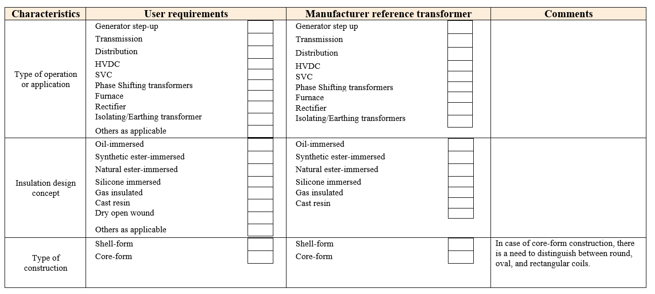
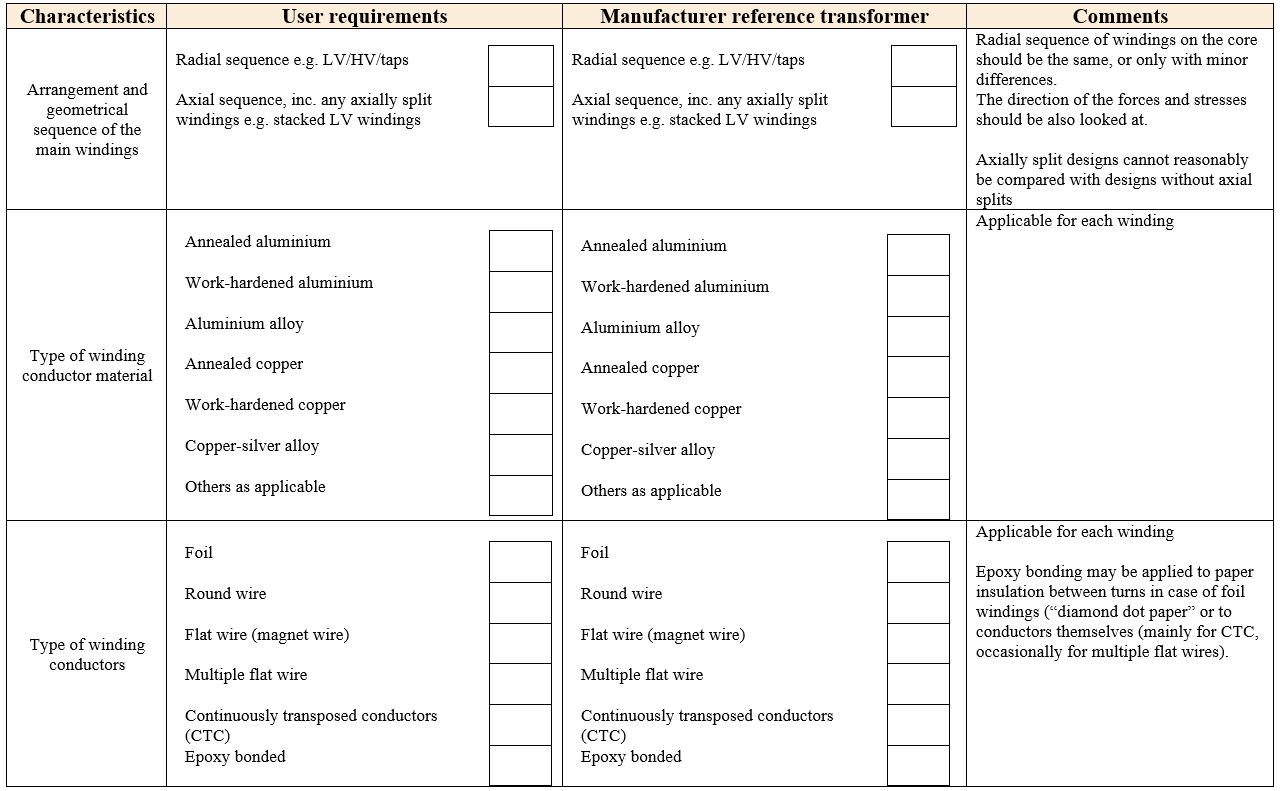
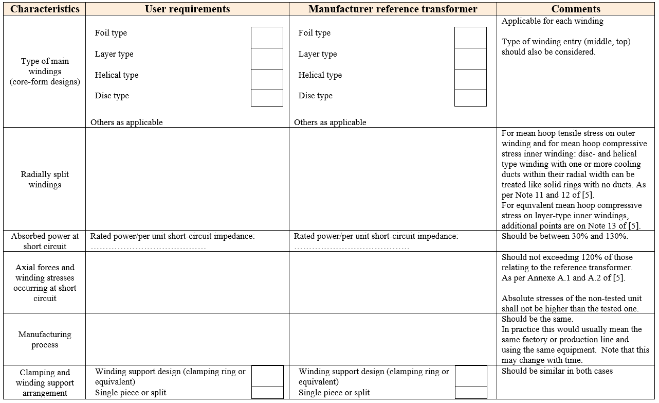

Table 1 - Guide to evaluation by comparison with a reference transformer
1.2. Evaluation by calculation during design review
Before the transformer is designed, the purchaser should provide sufficient information about the characteristics of the network to enable calculation of the steady state short-circuit currents using the method of symmetrical components. In practice this means specifying, for each network to which the transformer is to be connected, the positive-, negative-, and zero-sequence impedances (or range of).
Once the transformer has been designed, it is therefore evaluated on mechanical strength aspects.
The design review should check the relevant mechanical force and stress values appearing in the design as a consequence of the fault conditions specified. This is done following this guideline.
1.2.1. Calculation of short-circuit currents
It does not seem reasonable to assume infinite short circuit power for the network, especially where this would involve a large and unnecessary increase in design margins and hence costs. The reasonable limit would be the maximum breaking capacity of the circuit breakers. However, it is common for some purchasers to require calculation based on an infinite short-circuit power for the network. It is required for Special Purpose Transformers (SPT) (as defined in IEV).
The short circuit apparent power of the system is converted to an impedance that will be the same for calculations of short circuit currents in all positions of the OLTC.
- In some cases, it might be prudent to assume that the system voltage at the time of the short-circuit was more than 100%, e.g. 105% or 110%.
- The calculated value of impedance may be slightly different from the specified or required value, and there may be a slight difference between the calculated value and the measured value. This may result in a slightly different value of short-circuit current.
Other important aspects to consider:
- In YNynd transformers or autotransformers, the single-phase short-circuit current depends greatly on the ratio of the zero-sequence impedance to positive-sequence impedance of each system and whether the secondary system has generation (short-circuit apparent power)
- For three-phase transformers, the zero-sequence impedances should be calculated and should not be estimated using typical factors based on the direct-sequence impedances.
When reactors in series with the tertiary are used to limit short-circuit currents, it is necessary to calculate the unsaturated and saturated reactance. The reactance, expressed in percent, should be determined according to the location of the reactor, whether installed on the line side or within the delta winding. In the zero-sequence impedance model of the transformer, it is not correct to directly add the reactor reactance to the branch corresponding to the tertiary winding.
The transformer should be capable of withstanding phase-to-phase and phase-to-phase-to-ground short-circuits involving non-in-phase currents. The same consideration applies to transformers with zig-zag-connected windings.
1.2.2. Forces calculation
Essentially the forces on winding conductors are calculated from the current flowing through the conductor and the local magnetic field. As explained in [6], in a core-type transformer with two concentric windings and uniform and balanced m.m.f. distribution, the magnetic leakage field lines develop along the axial direction over almost the whole height of the winding and diverge in proximity of the winding ends. On the other hand, local distortions of the leakage field lines created by non-uniform or imbalanced m.m.f. distribution along the axial extension of the windings, lead to significant radial components of flux density. As a results of this behaviour, it is common to resolve electromagnetic forces into radial and axial components.
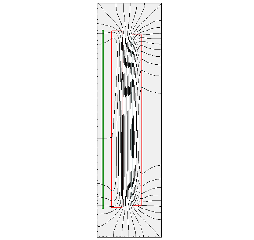
Figure 1 - Magnetic Flux Density Distribution in a Gapped Core
Accurate determination of forces, and especially axial forces, requires a detailed calculation of the magnetic field using a numerical method. Approximate calculations, mainly applicable to radial forces, can be made using analytical or empirical methods. Radial and axial forces should be calculated for the different cases considered for design purposes.
The result of the static calculation should be verified by calculating the axial resonance frequencies of the windings.
It should be demonstrated that the design strength of the windings and the clamping structure (e.g. clamp rings and tie rods or bars in case of a core-form design) including all external leads and accessories, with regard to the material and type of construction used, exceeds the calculated forces that will exist when the transformer is subjected to a through fault. These transferred forces can also be calculated using structural analysis. It could be noted that different assumptions or method may result in significant differences in material stresses for the same forces.
The following stresses should be calculated for both core and shell type transformers:
Core Form Transformer | Shell Type transformer |
| Mean hoop tensile stress on outer windings | Stress due to axial bending of conductors [between supports] |
| Mean hoop compressive stress on disc, helical, and single-layer inner windings | Compressive stress on paper insulation and on spacers in pancake coils |
| Equivalent mean hoop compressive stress on [multiple] layer-type inner windings | Compressive stress on [clamping structures] |
| Stress due to radial bending on conductors [between supports] | Tensile and bending stresses on core laminations |
| Stress due to axial bending on conductors [between supports] with disc and helical type windings | Tensile and bending stresses on tank re-enforcement structures |
| Compressive stresses on radial spacers with disc and helical type windings | |
| Compressive stress on conductor paper insulation with layer type windings | |
| Compressive stress on [winding end blocking] | |
| Compressive stress on [winding clamping platform] | |
| Tensile stress on tie rods [or tie bars] of the clamping structure |
1.2.1.1. Radial forces
Special considerations should be considered regarding radial forces.
As explained in [6] , “in a winding arrangement consisting of two physical windings, the conductors close to the main duct between windings are subjected to higher radial force per unit length compared with those at radially opposite locations.”
Free buckling may occur when transformer windings deform under the action of radial electromagnetic forces. As stated in [3], “it is recommended to make calculations assuming that inner windings are self-supporting. This means that the winding should withstand radial forces without relying on support from the core.”
Transformer configurations such as Lo-Hi-Lo, as well as cases involving single-phase short-circuits at the LV terminals of three-winding transformers with YNynd connections, should be considered. In these situations, tensile (hoop) stresses and compressive stresses in the windings may partly counteract each other, however, significant axial compressive forces can still develop and should be taken into account.
1.2.2.2. Axial forces
Axial forces appear as a consequence of the inclination of magnetic leakage flux lines at the ends of a pair of windings and by non-uniform or imbalanced m.m.f. distribution along the axial extension of the windings.
Special considerations regarding axial forces include the following:
- Axial forces should be calculated both inside and outside the core window, as magnetic boundary conditions can significantly influence the force distribution and, consequently, the sizing of the axial pressing system.
- Axial asymmetry between windings should be considered, as it can significantly increase axial forces during short-circuit conditions. Such asymmetry may be inherent in the design or may result from manufacturing tolerances or progressive winding displacement caused by repeated short-circuit events, making its effect difficult to evaluate accurately.
- The increasing use of dual LV designs for the integration of distributed renewable energy resources and battery energy storage systems should be considered. These designs often use stacked LV windings, which may produce significant axial forces when a short-circuit occurs on one LV winding but not the other. Certain design concepts, such as foil windings, may present additional challenges in this respect. The effect of inrush current should also be carefully assessed.
- The required axial pressing force should be determined with due consideration of the calculated short-circuit forces. Although the pressing system provides a constant pre-compression force, short-circuit forces are impulsive in nature and may impose transient mechanical demands that exceed the static clamping condition.
- The copper cross-section used for the calculation of the fixed stabilizing force should reflect the effective conductor area contributing to axial stiffness, as this directly influences the evaluation of winding stability under short-circuit forces.
- Forces and stresses in tie rods should be evaluated under short-circuit conditions, in addition to those resulting from clamping loads during lifting of the core-and-winding assembly.
- The mechanical adequacy of clamping rings and the axial pressing system should be assessed, particularly where detailed design information is not available during the design review to allow full validation of their short-circuit withstand capability.
1.2.2.3. Spiraling
Spiraling is a winding failure mode that is related to the effect of radial compressive forces which results in a deformation pattern typical of a helical type winding. Spiraling withstand is highly dependent on the design and process and very difficult to calculate. It has a great dependence on friction and clamping of the coil outlets.
End insulation design, mechanical support, and material selection are very important for the assessment of spiraling stability. The use of pressboard trapezoids is recommended, whereas the use of spacer columns should be avoided, as they may adversely affect winding stability. It is recommended to have experience with the commonly used support.
The significance of spiraling depends on the winding pitch, defined as the axial length of a single turn. Spiraling effects therefore become particularly relevant for windings with a small number of turns distributed over a large axial height, such as tap windings or certain LV windings.
1.2.2.4. Force calculation methods
Methods of short-circuit forces calculations are described in an article published in Electra Nº67 in 1979 [7], are listed below:
- Elementary formula for radial forces
- Image method (2D)
- Roth’s method (2D Cartesian)
- Rabins’ method (2D cylindrical)
- Finite element method (2D and 3D)
This publication has validated these methods and may therefore be used for the validation of short-circuit force calculation software. Additionally, the determination of the maximum axial compression, at the upper and/or lower supports, should also be considered.
1.3. Survey - Experience from end users
The survey was conducted to gather insights into end-user experience with the short-circuit evaluation of power transformers. It further relates in-service short-circuit failures to the methods used by users to verify short-circuit withstand capability during the purchasing stages, where this information is available.
The responses came from eight different countries: France, Germany, Malaysia, Canada, South Africa, Belgium, Austria, and the United Kingdom. Respondents represented different industries, including generation, transmission and distribution companies, railway companies, manufacturers, academics, and consultants.
The responses cover a total of 10 812 in-service transformers, excluding information submitted by the manufacturer. The following table shows the voltage range of the transformers covered in the survey.
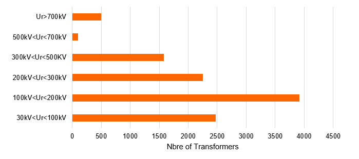
Figure 2 - Voltage range of transformers covered in the end-user survey
The first part of this survey was related to general consideration and especially how the end-users are ensuring the short-circuit withstand capability when ordering a new transformer. In general, end-users do not rely on a single approach, instead, they employ a combination of verification techniques to ensure compliance with applicable standards and design requirements.
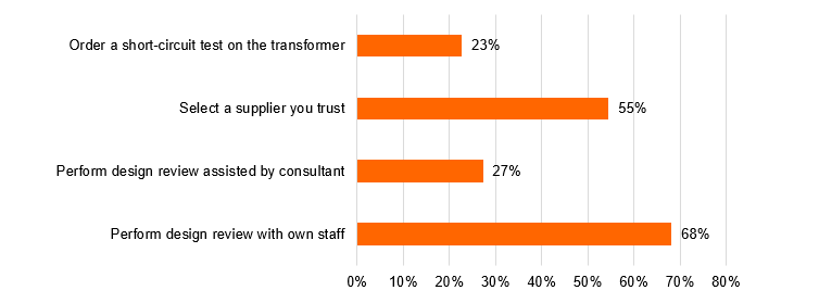
Figure 3 - Verification of short-circuit withstand capability of a new transformer
Note1: This result is not considering manufacturer responses.
Note 2: The sum is higher than 100% because for each solution, this is the number of Responders who are applying this solution compared to the number of Responders. Sometimes, the Responder can verify the short-circuit with different solution (ex: Select a supplier they trust, perform design review with their own staff, order a short-circuit test on the transformer)
Additionally, the end-users that select a supplier they trust based their decision on:
- Experience with the supplier in previous project
- Meaningful reference from other utilities
- A very good reputation in the industry
- Experience with short-circuit full scale test for previous project for the utility
- Significant number of short-circuit test have been performed by the supplier
Over the past 20 years, a total of 42 transformers have been subjected to short-circuit testing by the respondents, either on the transformer itself or on a representative model. Of these, 10 transformers failed during the first test and required retesting (23.8%). The observed failures were primarily attributed to design and manufacturing deficiencies.
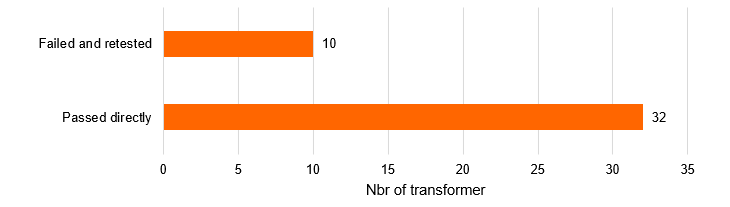
Figure 4 - Transformers who failed and passed the short-circuit test
Of the 10 812 transformers covered by the survey, 56 experienced an in‑service failure due to a short‑circuit over the past 10 years. Among these, detailed information, including root‑cause analysis, was available for 22 failures. The age at which these in‑service failures occurred ranged from 1 to 45 years. For most of the failed transformers, short‑circuit withstand capability had been assessed at the design stage primarily through calculation and comparison with a “similar” transformer. However, for some cases, this information could not be confirmed. It can be extrapolated that age is not a reason for falling.
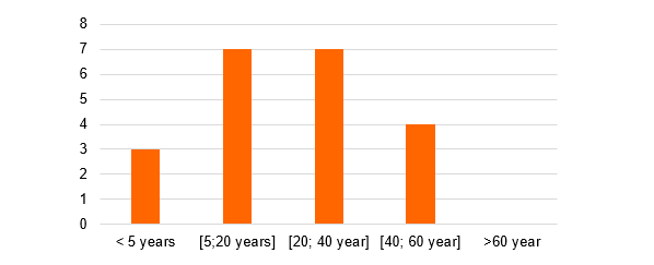
Figure 5 - Age of transformer for the in-service failures shared on the survey
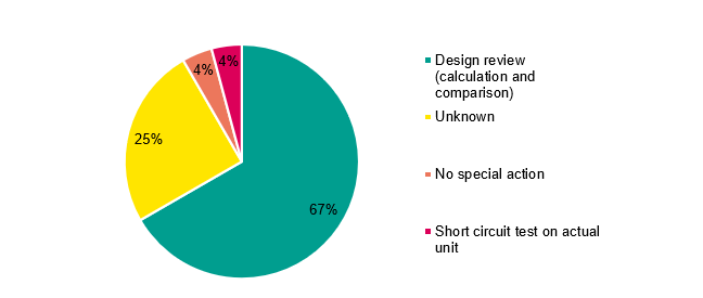
Figure 6 - For the in-service transformer failures, short-circuit capability method of verification at the time of delivery
Additionally, for the 22 failures reported in the survey, the short-circuit current through the transformer at the time of failure was, in most cases, below the rated short-circuit current.
| Short-circuit current recorded value at the time of the failure | Rated Short-circuit current | |
|---|---|---|
| Failure A | 11 kA | 13 kA |
| Failure B | 20.31 kA | 94.96 kA |
| Failure C | 8.7 kA | 13.4 kA |
| Failure D | 10 kA | 50 kA |
| Failure E | 8.3 kA | 9 kA |
| Failure F | 30 kA | 32 kA |
Based on the 22 failure cases reported in the survey, 36.8% of short‑circuit events were attributed to human error, for example, energizing a transformer connected to an earthed busbar. Additionally, 21.1% of the analysed transformers experienced short‑circuit failures caused by animal intrusion. This is closely followed by energizing transformers onto an existing fault. However, independently of the root cause of the short -circuit, the transformer should withstand.
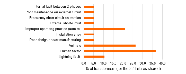
Figure 7 - Root-cause analysis for the 22 in-service transformer failures reported in the survey
The reported failures showed the following main forms of transformer damage resulting from short-circuit events:
- Collapse or deformation of windings
- Fire‑induced destruction of the transformer
- Tank rupture
- Displacement of spacers and insulating barriers
- Variations in impedance values (upon testing)
All the reported failure modes are regarded as major failures.
1.3.1. Survey conclusion
The survey results indicate that, although the short-circuit withstand capability of most transformers had been verified through design review, in-service failures still occurred. While some initiating short-circuit events were associated with operational or human error, the ability to withstand accidental short-circuit conditions remains an inherent design requirement. Transformer damage should not occur where the imposed fault current remains within the validated design withstand limits, as was the case for the fault events assessed in this survey.
The survey further indicates that design review, comprising short-circuit force calculations and comparative assessments against a reference transformer, remains the most commonly applied method for verifying short-circuit withstand capability. In contrast, only 23% of respondents reported that their transformers are subjected to actual short-circuit testing.
2. Manufacturing impacts
To ensure adequate short circuit withstand capability, it is important to follow consistent and standardized manufacturing procedures and methods while maintaining high quality standards.
To a large degree, the design criteria for short circuit performance are determined by factors influenced by material properties and manufacturing practices. These are the main factors as mentioned in [6]:
- Mechanical properties of conductor materials, insulation materials, structural metals
- Dimensional variability of materials
- Turn distribution within windings
- Radial tightness on conductors within the total winding assembly
- Axial compression loading on the windings
- Accuracy of positioning of the winding supports
Strict material control procedures should be established, together with standardized manufacturing instructions.
This includes control of the physical and chemical characteristics of copper conductors, such as tensile strength, insulation strength, and the bonding properties of the epoxy used on CTCs.
The manufacturing processes associated with the winding, insulation system, and complete core-and-winding assembly shall be subject to stringent process control. This includes verification that winding positioning remains within specified tolerances, that winding support and clamping arrangements are correctly implemented, and that final drying and oil impregnation processes are effectively executed and controlled.
Additional points:
Verification of the 0.2% proof stress (Rp0.2) of the conductors used in manufacturing shall be performed during factory inspections and validated against the values assumed in the design calculations. Although a transformer may satisfy the design review requirements based on the specified Rp0.2 value, it is essential to confirm that the conductors used in winding manufacturing achieve the same minimum Rp0.2 level assumed in the design.
Similar considerations apply to the curing of epoxy-bonded windings. The curing process and the resulting bond integrity shall be demonstrable and traceable through manufacturing records for each transformer.
It is therefore essential that mechanical design calculations be based on the minimum guaranteed yield strength of both the conductors and all structural components contributing to the mechanical integrity of the transformer.
3. In service experience on short-circuit failures and best practices
3.1. Case Study - Short circuit failure - Animal interference
A 250MVA 400/30kV SVC transformer, which had been in service for 11 years failed when a civet cat made contact between the white and blue phase breaker of capacitor bank in an SVC circuit on the 30kV side. Diagnostic tests (DGA) done revealed high energy arcing. Severe mechanical and electrical damages to an HV winding were observed. The observed damages indicated that this transformer suffered a severe through fault. It was then taken to the workshop for further investigations. On inspection at the workshop, the blue phase HV winding conductors along the center of the winding were found to have bent. This bending of the conductors suggested movement between the winding and spacers due to high forces experienced by the winding, and this resulted in damaged insulation, leading to a turn-to-turn fault. Moreover, the winding clamping structure was damaged, and this resulted to a loss of pressure on the winding, which meant loss of resistance to forces during the short circuit.
The tank was ruptured at various spots due to severe internal pressure during this failure.
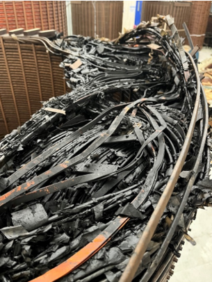
Figure 8 - Damage on the winding view 1
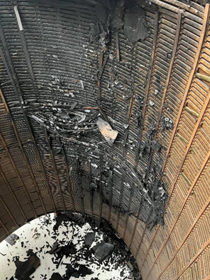
Figure 9 - Damage on the winding view 2
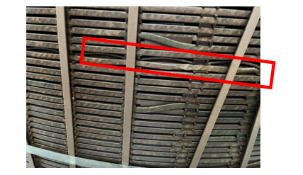
Figure 10 - HV winding conductors bent
3.2. Experience on short-circuit tests at a major utility
The utility applies a consistent set of criteria when deciding whether a transformer shall undergo short‑circuit testing. These criteria are applied uniformly to transformers supplied by all manufacturers and include the following:
- Strategic importance of the transformer family within the network
- Number of transformers of the same design
- Possibility of performing “umbrella” tests
- Transformer impedance
- Confirmed expertise of the manufacturer
- Availability of laboratory capacity
- Calculation and simulation results provided during the design review
- Factory visits conducted as part of the design review
Depending on the outcome of this assessment, a short‑circuit test may be required. When performed, the short‑circuit test is expected to provide several benefits. It validates the manufacturer’s design expertise and the ability of the transformer to withstand the mechanical stresses generated during short‑circuit events. It also serves to validate the reliability of the supplier’s design tools used to simulate mechanical stresses, as well as the level of control over manufacturing and quality assurance processes required to ensure that the product delivered is consistent with the approved design throughout all stages of production.
Experience has shown that calculation results alone do not fully describe transformer behaviour under short‑circuit conditions, as the phenomena involved are too complex to be completely captured by analytical methods. Several transformers that failed short‑circuit tests exhibited significant calculated design margins.
When a short‑circuit test is required, the acceptance criteria are aligned with IEC Standard 60076‑5. The test results, together with all measurements and verifications performed during the test, shall not reveal any fault conditions. Following the short‑circuit test, all applicable routine tests shall be successfully repeated, including the lightning impulse test where required. In addition, external and internal inspections of the transformer shall not reveal any defects or evidence of internal electrical discharge.
To date, the utility has carried out 20 short‑circuit tests on 12 power transformers. The failure rate at the first test attempt was 40% for transformers with a rated power below 100 MVA and 100% for transformers rated above 100 MVA. Two transformers were subjected to three successive short‑circuit tests each; in one of these cases, the transformer did not successfully pass any of the tests.
The observed failure modes include the following:
- Spiralling of a layer winding
- Axial collapse resulting from magnetic centring issues in an axially split winding design
- Failure of lead supports
- Dielectric failure
Although the majority of short‑circuit tests conducted have ultimately been successful, sometimes after multiple test attempts, the apparent success rate should be interpreted with caution. Short‑circuit tests are not systematically required for all transformers but are instead selectively applied to those presenting the highest perceived risk of failure.
The utility has been performing mechanical design reviews for approximately 12 years, during which technical specifications have progressively incorporated additional validation requirements. Extensive feedback has been accumulated from dielectric and temperature‑rise tests, as these are type and routine tests and are relatively inexpensive to perform. In contrast, experience with short‑circuit tests remains limited due to their high cost.
Nevertheless, short‑circuit testing remains the only comprehensive means of validating the adequacy of transformer design, manufacturing quality, and long‑term mechanical reliability under severe fault conditions. It is therefore recommended to continue requiring short‑circuit tests for transformers where the volume and strategic importance justify such testing, while optimizing their overall impact by applying “umbrella” testing approaches whenever technically feasible.
4. Concluding remarks
In making the decision whether or not to test, the purchaser will need to consider the following factors:
Technical factors:
- The size of the unit and the practicality of testing, small easily tested units may be easier and cheaper to test than to review the design calculations.
- The number of units being purchased – a large batch of identical units provides a lower per-unit cost of design review and type (special) testing, and a higher consequence of finding a common design or manufacturing fault in service if many units are affected.
- The criticality of the unit, what are the consequences of a failure in service in terms of the function the unit is intended to fulfil and the safety of people and the environment?
- The impedance of the transformer, this determines the ratio of fault and normal currents and is in many ways indicative of the difficulty of designing and proving the transformer for short-circuit capability. Typical reference impedance values are given in standards. Very high impedance makes a transformer less likely to fail in service from short-circuit currents but creates other issues.
- The operating environment in terms of the likelihood and magnitude of short circuits. This can range from large transformers in high impedance networks that rarely if ever encounter design-base level short circuits to trackside or industrial transformers that experience low impedance faults on a regular basis.
- The availability of previous experience of testing either of models or complete units from the manufacturer and factory, and the relevance of that experience to the proposed unit. This can range from a manufacturer that has made and tested many similar transformers to a new manufacturer or one looking to extend the range of their design and manufacturing capability.
- The impact of testing on the procurement programme and the uncertainties that this can introduce.
- The availability of suitably experienced staff to carry out a meaningful design review. There is little point in asking a manufacturer for design parameters and calculations for review if these cannot be critically analysed. It is inconceivable that a manufacturer would deliberately design a transformer outside their design rules, so an understanding of where the deign rules come from and their validity is required. This requires a very high level of understanding, which is most likely to be present in large utilities and consultancies. The design review should be a collaborative process with both parties willing to listen, learn and reconsider.
All of the above mean that the decision looks very different for the purchase of a large batch of distribution transformers from a new manufacturer, where testing is clearly the best option, to the purchase of a one off 1000 MVA high impedance autotransformer that will be used in a redundant parallel configuration with an existing unit in a network that rarely sees short-circuits, where design review is likely to be preferred. There are of course many intermediate cases, such as primary substation transformers especially in radial networks, where testing is possible but expensive, and the consequence of failure is very great. In these cases, the usual asset management skills, fundamentally balancing cost and reliability, taking account of multiple considerations and constraints should be used.
References
- IEC 60050, International Electrotechnical Vocabulary, 2001.
- Giorgio Bertagnolli, Short-circuit Duty of Power Transformer, Published by ABB Switzerland, 2006.
- Gilson Bastos et al, CIGRE Green Book: Transformer and Reactor Procurement - Chapter 10, 2022.
- CIGRE, Technical Brochure 939 : Analysis of AC transformer reliability, 2024.
- IEC 60076, Power transformer - Part 5: Ability to withstand short circuit, 2006.
- ABB, Power Transformer & Short Circuits - Evaluation of the short-circuit performance of power transformers, 2014.
- CIGRE ELECTRA, N°067 : Calculation of Short-circuit Forces in Transformers, 1979. ref ELT_067_1