Dual star PMSM drive system behavior analysis under switch short-circuit fault in motor operation mode
Authors
Elyazid AMIROUCHE, Said AISSOU, Ali BERBOUCHA, Kaci GHEDAMSI, Djamal AOUZELLAG - Université de Bejaia, Faculté de Technologie, Laboratoire de Maitrise des Energies Renouvelables, Algerie
Nabil BENYAHIA - Geeps group of electrical engineering, France
Jean-Frederic CHARPENTIER - Institut de Recherche de l’Ecole navale (EA 3634, IRENav), French Naval Academy, France

Summary
This research work is a comparative study aimed to analyze the behavior of three widely used control techniques: Hysteresis Current Control (HCC), Field-Oriented Control with Space Vector Modulation (SVM-FOC), and FOC with Carrier Based Pulse Width Modulation (CBPWM-FOC), in response to a short-circuit on an IGBT power switch of a two-level converter. These techniques are applied to a Dual Star Permanent Magnet Synchronous Machine operating as a motor. The objective is to understand how these techniques react and perform in a switch short-circuit situation, in order to determine their performance and effectiveness in this specific context. The comparative approach between FOC and HCC control techniques is based on the analysis of electrical and mechanical properties of the machine. We compare the torque behavior and the phase currents by evaluating the current Total Harmonic Distortion (THD), paying particular attention to the most prevalent harmonics. The system modeling is achieved using simpowersystem components of the Simulink library, which improves the accuracy of the drive simulation results. The results obtained from MATLAB simulations revealed that the performance of the HCC control technique is much superior to that of the FOC technique, as the stator currents contain less harmonics, are less perturbed, and the torque is of better quality with less oscillations.
Keywords
Dual star permanent magnet motor, power switch fault, short-circuit fault, hysteresis current control, Field oriented control, PWM converter1. Introduction
Rotating electrical machines have a crucial role in the global industrial sector [1], [2]. Their performance is continuously enhanced through the use of power electronics and advanced control methods [3], [4]. The integration of converters with machines has experienced significant advancements due to the development of sophisticated control techniques and power devices [5]. Power electronics provide greater operational flexibility for rotating machines, enabling additional features such as speed regulation, torque control, soft startup and shutdown, and energy recovery. By incorporating static converters, machines can operate smoothly in all four quadrants. It’s important to note that using power electronics to drive electrical machines poses new challenges to the design of modern electric machines, as the high frequency components of the current induce more eddy currents, causing more electric, mechanic, and thermal stress.
Despite the high reliability achieved through converter-machine integration, drive systems are not exempt from failures. Failures can occur, primarily originating from electronic components such as power switches (IGBTs) or control elements, including issues related to galvanic or opto-electronic isolation breakdowns [6], [7]. One of the most critical failures in these systems is the short-circuiting of an IGBT switch (SSC for Switch Short Circuit), which can lead to a complete shutdown of the drive [8]. This outcome is highly problematic, especially for electric vehicles and remote power systems, as unscheduled shutdowns can lead to catastrophic failure and significant financial losses. This failure can be caused either directly by the power component or indirectly by a nearby or remote-control circuit [9], [10].
This fault is very common in power electronic drive systems. It can originate from many sources, either the control circuit which generates the gate signals such as a microcontroller or processor, the gate driver circuit which isolates the control and the power circuits, or the power switch itself [11], [12].
When this fault occurs, the system is usually shutdown by the integrated protections,such as fuses. Elsewhere, the system can be seriously damaged, especially the DC source, which is short-circuited when the complementary switch of the faulty leg is closed. This leads to important current flow from the DC source through the healthy remaining switch, and can cause damage to the remaining switch and the DC source.
The other threat to the drive system is the uncontrolled currents and torque of the machine. In the event of an SSC fault, the machine becomes instable, generates more vibrations, noise and heat, and can lead to its complete destruction [13]. In some application areas, the system cannot be stopped due to security reasons, or continuity of service obligations. In which case, the drive system must be able to continue running even with reduced power, and accept some performance degradation [14]. In order to achieve this goal, this two-part research work is intended to acquire necessary knowledge about the drive system behavior in the case of SSC fault in order to develop a control algorithm able to maintain the operation of the system under fault.
The SSC fault is not well studied in the literature. In most cases, only classic space vector PWM technique is considered in the study, and intend to propose fault-tolerant techniques, instead of studying the effect of the fault itself and the behavior of the system in this case[15], [16]. The authors in [17] proposed a non-economical solution to mitigate the SSC faut on a three-phase interior magnet synchronous machine drive system, consisting on a six-leg converter. This procedure doubles the number of active switching devices needed to drive a single machine, which increases the system cost and probability of failure. In [18], it is proposed to mitigate SSC fault by connecting the neutral point of the machine to a DC bus midpoint, that is created using DC bus capacitors, and two redundant switches. To achieve this, the voltage of the capacitors must be balanced, and the authors used two third-order integral-lead controllers to do so, increasing the system’s cost unnecessarily. However, the claim that the paper investigates both SSC and open-switch fault is imprecise, as the authors treat the two faults equally, and realize them by simply turning off the faulty leg of the converter. Indeed, the SSC fault is not the same as open-switch fault, as it is not possible to remove the short-circuited switch without human intervention, or use of other switches, breakers or fuses. Hence, the faulty machine’s phase will be permanently connected to the positive or negative DC bus terminal, depending on the faulty switch.
Moreover, conventional research works conduct simulation tests by solving the differential equations of the drive system in Matlab/Simulink environment. The modeling is always achieved by adopting many simplification criteria that often reduce the accuracy of the model, especially the power switches modeling, in which internal resistance and forward voltage are not considered at all. In the present work, the system modeling is achieved using SimPowerSystem components of the Simulink library, which improves the accuracy of the drive simulation results. This technique was first introduced in [19], where its effectiveness has been proven, especially when dealing with faults.
When an SSC fault occurs, the behavior of the machine depends solely on the used control technique. It is observed, based on the various simulation tests we conducted, that there is no need to develop more sophisticated control schemes or add extra active components to allow the system to operate, as the classical ones can give good performances without the need to increase the complexity of the control system.
In this scope, this paper analyzes the effect of short circuit fault of an IGBT switch on the control scheme of a dual star permanent magnet synchronous motor (DSPMSM). This fault can impact the performance of the converter, leading to interruptions in the drive system. In order to better understand this phenomenon, we propose a comparative study aimed to analyze the effect of three widely used control techniques on the drive system behavior: Field-Oriented Control with Space Vector Modulation (SVM-FOC), FOC with carrier-based PWM (CBPWM-FOC), and Hysteresis Current Control (HCC). This study aims to evaluate the response of these techniques and their effect on both healthy operation and during SSC fault, to determine their performance and effectiveness. The results of this study will enable us to better understand the performance of these control techniques and identify the one that is most suitable for dealing with a short circuit in the drive system.
2. System description
The studied system is presented in Figure 1. Two three phase two-level converters are connected to a DSPMSM to feed the machine with electric power. An RL filter has been inserted between the converter and the machine to enhance the stator current quality, especially for the HCC technique, while accepting insignificant power losses in the form of joule effect and core losses. A Fuzzy Logic Controller (FSC) is used in this system to get a precise control of the machine speed [20].
In motor operation mode, a DC source supplies the converters which operate as inverters, and the machine feeds a mechanical load which imposes a resistive torque on the machine’s shaft.
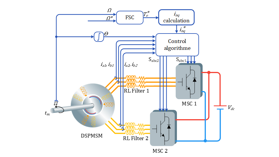
Figure 1 - General scheme of the studied system
2.1. Dual star permanent magnet synchronous machine modeling
Figure 2 shows the phases configuration of a DSPMSM, where the two stars are shifted by 30 electrical degrees, with two isolated neutral points.
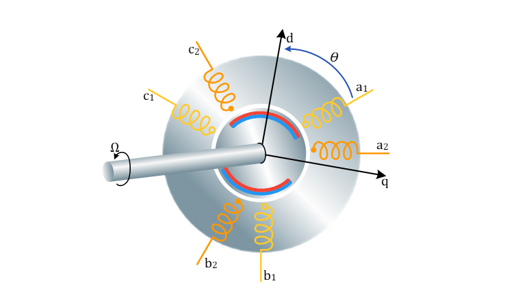
Figure 2 - Dual Star Permanent Magnet Synchronous Machine
Despite the modeling technique used in this work, the mathematical equations of the machine are necessary to develop the control algorithm.
Many mathematical models are proposed for the DSPMSM in the rotating reference frame. In this paper, the model proposed by [21] is used, which describes the machine by the mean of two decoupled sub-machines. The first, in which the direct and quadratic components are respectively noted and , is responsible for the torque and flux generation, and the second, in which the direct and quadratic components are respectively noted and , describes the losses inside the machine. This model is called extended d-q model. As previously reported in [22], the extended d-q model of the DSPMSM is described by the following equations:
(1)
In this equation set, is the electrical frequency, and the terms
are the cyclic inductances of the machine given as:
(2)
Where Ll and m are respectively the leakage and mutual inductance of the machine.
The mechanical behaviour of the machine is described by the following equation:
(3)
with J the total inertia of the rotating mass, Ω the mechanical angular speed of the machine, tm the mechanical torque applied on the machine’s shaft, and tem the electromagnetic torque developed by the machine given as:
(4)
This equation can be simplified in case of smooth pole machine, which leads to:
(5)
This mathematical model is used for the development of the control algorithms, while the machine itself is simulated using another modeling technique, using SimPowerSystem component of the MATLAB/Simulink library, as stated in the introduction.
2.2. Field-oriented control
The FOC technique is widely used to precisely control the speed of AC electrical rotating machines. It permits a decoupled control of torque and flux as in DC machine. Figure 3shows a general scheme of the FOC algorithm.

Figure 3 - FOC algorithm
The transformation described by equation (6) is used to transform the currents to the extended d-q frame.
(6)
Where
(7)
According to equation (5), the current component responsible for torque production is , so this component is used to control the torque of the machine, while all the other currents are regulated to zero to ensure minimum power losses, minimum current amplitude, and to fully use the permanent magnets flux.
Equation (1) shows that a mutual coupling exists between the d and q components of each sub-machine. Minimizing the effect of this coupling will improve the performance of the PI controllers. This is accomplished by adding the following terms at the output of the regulators:
(8)
Once the voltage references are calculated by the PI regulators, the trigger signals, used to control the state of the power switches, are generated using a signal generation technique, such as the carrier-based PWM, or the SVM.
2.3. Hysteresis current control
The hysteresis current control is a very simple, but powerful control technique. It consists of generating a proper converter control signal in order to apply a desired sinusoidal current to the machine. The trigger signals are generated by hysteresis comparators, by comparing the phase current and the reference current in the natural reference frame ( reference frame). If the error (i.e., the difference between the two values) exceeds a predefined limit (hysteresis upper limit), the trigger signal (where is one of the converter legs: , , , etc.) is set to zero in order to decrease the current. When the error is below the hysteresis lower limit, the trigger signal of the concerned converter leg is set to one in order to increase the phase current. The Figure 4 shows a simplified scheme of the HCC algorithm.
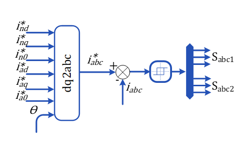
Figure 4 - Hysteresis current control scheme
The reference current is generated based on desired d-q currents in the extended d-q reference frame, then transformed back to abc reference frame using the following transformation presented in equations (9) and (10), with α the displacement angle between the two stars of the machine :
(9)
(10)
The main drawback of this control technique is the use of the hysteresis controllers. Because of this, the current oscillates around the reference value, which causes the apparition of medium frequency harmonics. To attenuate theme, an RL filter is often advised between the converter and the machine.
3. Converter switch short circuit fault
In the case of motor operation mode, or in other words, in inverter operation mode of the converter, the electric power flows from the DC bus to the AC side. When a switch is short circuited, for instance the top switch of phase A, the current flows to the AC side normally when the control signal of this phase is set to 1 (Sa=1 on Figure 5.a), and is suddenly interrupted when Sa becomes 0 (Figure 5.b). This is the theoretical behavior when ideal switches are considered, but practically, the behavior is much more complex than this. A more representative situation is considered in this work by taking into account the internal resistance and forward voltage of the IGBTs. To model the short-circuit fault, the gate signal of the considered switch is permanently set to 1, while the freewheeling diode remains functional. This is often caused by driver failure, amplification and isolation circuit, or by a physical short-circuit on the IGBT itself.
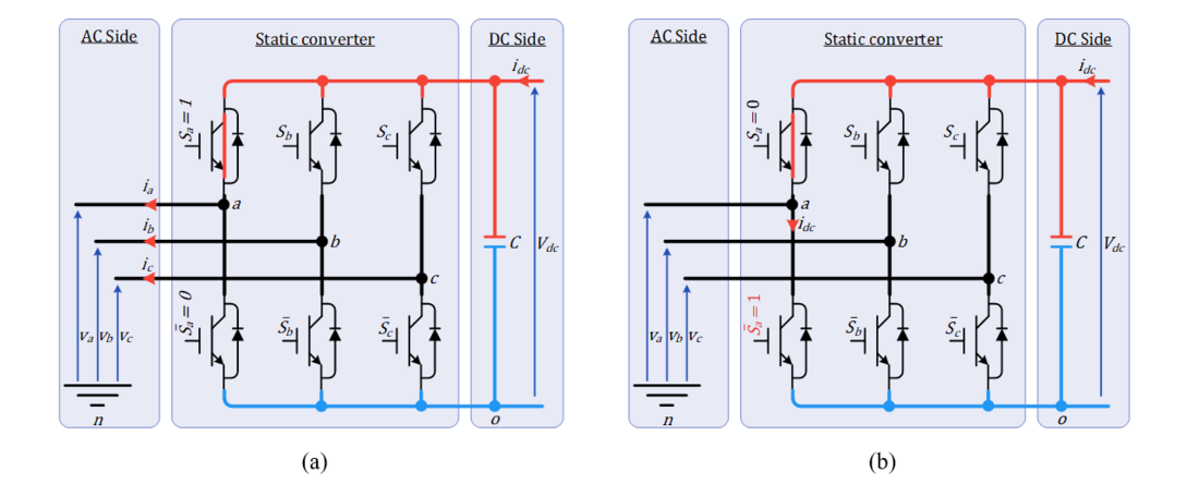
Figure 5 - Behavior of the currents in a three-phase inverter with a SSC fault on phase A: (a)Sa=1 (b)Sa=0
In such a situation, the trigger signals applied to the converter depend on the technique used to generate them. The standard SVM is severely degraded because of the lack of some control vectors, as can be shown in Figure 6. It can be seen that half of the vectors are affected (those with Sa = 0). The vectors V0, V2, V4 and V6 become the same as V1, V3, V5 and V7 respectively. So, when the control algorithm tries to apply the vector V2, actually, it’s the vector V3 that will be applied instead, and so on. Based on this, all control technique based on space vector representation should not work properly, and become highly instable due to the asymmetry caused by the fault.
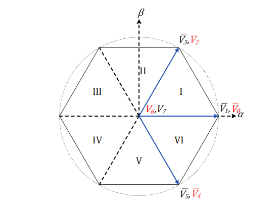
Figure 6 - Configuration of three-phase SVM technique with SSC fault on the top switch of phase A, in red the faulty vectors
However, the behavior of the carrier-based PWM and the hysteresis control techniques are completely different from this, as the generated trigger signals are independent from a leg to another, and doesn’t form a predefined vector combination as in SVM technique. So only the trigger signals of the faulty leg are influenced by the fault, while the remaining legs are still able to apply the desired voltage without problem. However, as the machine forms a coupled six phase system, a fault in a phase will inevitably influence the comportment of the remaining phases, as completely isolated phases cannot be achieved.
4. Simulation results and discussion
In what follow, the behavior of the machine is presented, (simulation results of HCC, FOC-SVM, and FOC-CBPWM). The motor is first driven to a speed of 42 rad/s with a nominal mechanical torque of 17 kN.m. At simulation time 1.5s, a SSC fault is created on the top switch of phase A1 by forcing its control signal to be 1.
First of all, the torque of the motor is presented in Figure 7.a. It’s clear that, in healthy mode, the quality of the torque is roughly the same for all three control techniques (Figure 7.b). When the fault occurs, the three control techniques present different behaviors. As previously predicted in section III, the FOC associated with SVM is highly instable, and has the worst performances over the other techniques, with torque oscillations reaching ±179.5%. Practically, the machine will be damaged quickly if it’s not stopped, as the vibrations may destroy the bearings and the mechanical parts of the system. The FOC-CBPWM technique generates oscillations on the torque that reach±92.2%, which also can be very harmful to the machine. The HCC control technique, however, ensures better operation with minimum torque oscillations compared to the two other techniques, not exceeding ±50.6%. In this condition, the machine can still ensure the operation for a longer time in emergency situations, without requiring immediate system shutdown.
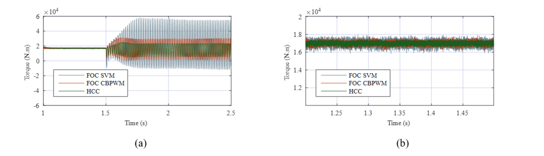
Figure 7 - Machine’s torque evolution before and after the SSC fault (a) with a zoom on the healthy region (b)
Figure 8 to Figure 10 show the stator currents of the machine in healthy and faulty conditions. As initially predicted in section III and confirmed by the torque behavior, the currents of the FOC-SVM technique are highly unbalanced, perturbed, and present a high DC component. Authors of [23] affirm that the continuous stator current component is very dangerous for PM machines, since it induces strong reverse flux that can permanently demagnetize the magnets. In the other hand, the HCC control technique preserves good quality currents with a minimum increase in the amplitude, and are less perturbed in the event of a SSC fault. The carrier-based PWM FOC technique shows medium quality currents, as they are less perturbed comparing to the SVM technique, and present some continuous components on the phase currents.
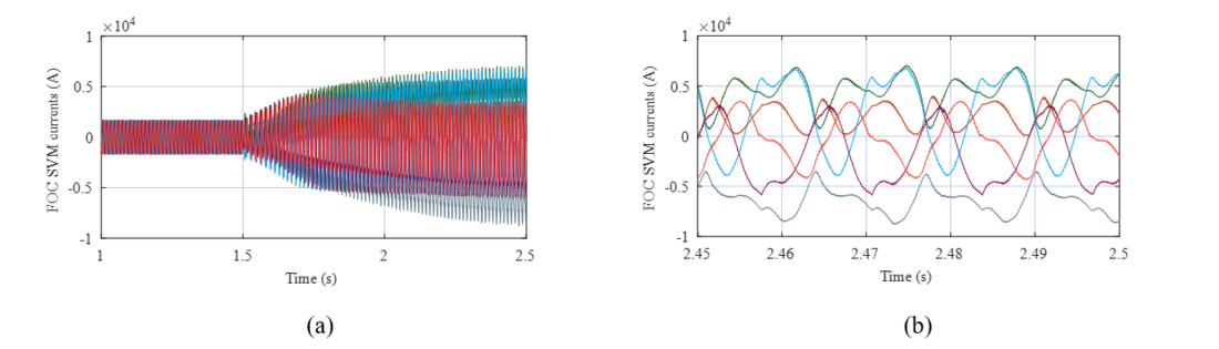
Figure 8 - FOC-SVM controlled machine stator currents before and after the SSC fault (a) with a zoom on the faulty region (b)
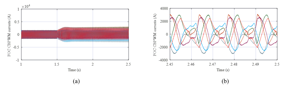
Figure 9 - FOC-CBPWM controlled machine stator currents before and after the SSC fault (a) with a zoom on the faulty region (b)
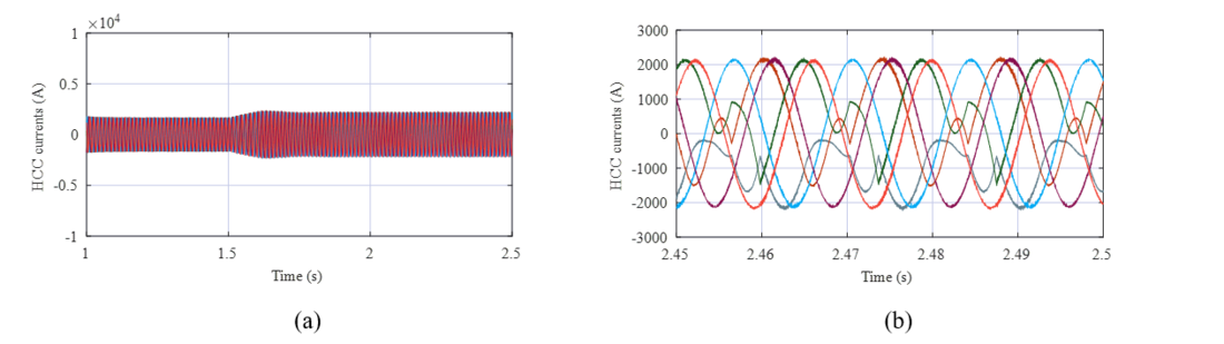
Figure 10 - HCC controlled machine stator currents before and after the SSC fault (a) with a zoom on the faulty region (b)
Table 1 shows a resume of all the collected information about the machine’s behavior in faulty situation, including torque ripples, and THD of the stator currents.
It is possible to conclude that the FOC-SVM technique caused a substantial increase in the amplitude of the stator currents, while being very rich in harmonics, mostly of orders 0 (DC), 2 and 3, which increase the THD of the current. It can also be noted that the increase in the amplitudes of the stator currents is unbalanced, and is very different from one phase to another. The FOC-CBPWM causes less increase in the amplitude of the stator current, and less harmonic distortion, but with unbalanced phases. Meanwhile, in the HCC technique, it can be observed that the currents of the second star of the machine remain unaffected by the fault in term of harmonic content, while presenting an increase of about 34% to compensate for the loss of power of the first star. It also ensures better current quality in term of phase balancing and harmonic content.
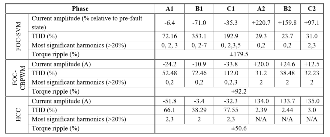
Table 1 - Machine’s Electrical and mechanical behavior under SSC
It can be concluded that, in healthy mode, it’s more suitable to control the machine with the FOC-SVM technique, as it practically presents better performances than the other techniques, and works with a constant switching frequency, which ensures better control over switching losses and, by consequence, allows longer life span of the converter. However, when a SSC fault occurs, it’s more suitable to switch to another control technique which ensures better performances in this situation, which is the HCC technique.
5. Conclusion
In this first part of the work, the behavior of the DSPMSM drive system in motor operation mode with an SSC fault is studied. The system was modeled in Matlab/Simulink environment, and them simulated using various basic well-known control techniques, namely Hysteresis Current Control (HCC), Field-Oriented Control with space vector modulation (SVM-FOC), and FOC with carrier-based PWM (CBPWM-FOC). The system model was implemented in Matlab/Simulink environment using a non-conventional simulation technique.
The results showed up the superiority of HCC performance compared to the other techniques during SSC fault, which make it a preferable choice to operate the machine in SSC fault situation. It produces a better torque quality than the other techniques, and keeps the currents of the second star of the machine undisturbed in term of current quality.
These observations will be used in a future work to elaborate a fault-tolerant control technique that is able to preserve the continuity of service with a minimum performance degradation of drive system.
Declaration of conflicting interests
The authors declare that they have no known competing financial interests or personal relationships that could have appeared to influence the work reported in this paper.
References
- F. Z. Latrech, A. B. Rhouma, and A. Khedher, “FPGA implementation of a robust DTC-SVM based Sliding Mode Flux Observer for a double star induction motor: Hardware in the loop validation,” Microelectronics Reliability, vol. 150, p. 115118, Nov. 2023, doi: 10.1016/j.microrel.2023.115118.
- N. Murali, V. P. Mini, and S. Ushakumari, “Design and implementation of field-oriented control based permanent magnet synchronous motor drives for electric three-wheelers,” Journal of Power Electronics, vol. 23, no. 4, pp. 637–648, Apr. 2023, doi: 10.1007/s43236-023-00597-0.
- S. Aissou, E. Amirouche, K. Iffouzar, K. Ghedamsi, and D. Aouzellag, “Online position error correction technique for sensorless control of multipole permanent magnet machines,” International Journal of Power Electronics and Drive Systems (IJPEDS), vol. 14, no. 4, p. 1929, Dec. 2023, doi: 10.11591/ijpeds.v14.i4.pp1929-1936.
- Y. Pang et al., “Model predictive control of nine-switch converter with output filter for independent control of two loads,” Journal of Power Electronics, vol. 21, no. 1, pp. 224–234, Jan. 2021, doi: 10.1007/s43236-020-00145-0.
- M. Giesselmann, “Computer Simulation of Power Electronics and Motor Drives,” in Power Electronics Handbook, Elsevier, 2024, pp. 1365–1385. doi: 10.1016/B978-0-323-99216-9.00030-5.
- C. Xing, Y. Zhu, J. Wang, and Y. Lin, “Fault-tolerant control of in-wheel switched reluctance motor drive systems for vehicles under regenerative braking condition,” Journal of Power Electronics, May 2024, doi: 10.1007/s43236-024-00852-y.
- B. Tian, R. Lu, and K. Wang, “Single-phase fault diagnosis for five-phase permanent magnet synchronous motors based on neutral voltage observation,” Journal of Power Electronics, vol. 23, no. 10, pp. 1461–1472, Oct. 2023, doi: 10.1007/s43236-023-00642-y.
- T. Shoji, M. Kuwahara, and M. Usui, “Dependence of Short-Circuit Withstand Capability of SiC MOSFETs on Short-Circuit Failure Time,” IEEE Trans. Power Electron., vol. 36, no. 10, pp. 11739–11747, Oct. 2021, doi: 10.1109/TPEL.2021.3073991.
- U.-M. Choi, F. Blaabjerg, and K.-B. Lee, “Study and Handling Methods of Power IGBT Module Failures in Power Electronic Converter Systems,” IEEE Trans. Power Electron., vol. 30, no. 5, pp. 2517–2533, May 2015, doi: 10.1109/TPEL.2014.2373390.
- R. Shan, J. Yang, and S. Huang, “Open-circuit fault diagnosis of three-phase PWM rectifier circuits based on transient characteristics and random forest classification,” Journal of Power Electronics, vol. 24, no. 1, pp. 130–139, Jan. 2024, doi: 10.1007/s43236-023-00704-1.
- S. Mohsenzade, J. Naghibi, and K. Mehran, “Reliability Enhancement of Power IGBTs under Short-Circuit Fault Condition Using Short-Circuit Current Limiting-Based Technique,” Energies (Basel)., vol. 14, no. 21, p. 7397, Nov. 2021, doi: 10.3390/en14217397.
- T. Li, G. Du, Y. Lei, and S. Chen, “Open-circuit fault diagnosis for OEW-PMSM drives based on finite-control-set model predictive control,” Journal of Power Electronics, vol. 22, no. 2, pp. 266–276, Feb. 2022, doi: 10.1007/s43236-021-00360-3.
- X. Wang, Z. Wang, M. Gu, B. Wang, W. Wang, and M. Cheng, “Current Optimization-Based Fault-Tolerant Control of Standard Three-Phase PMSM Drives,” IEEE Transactions on Energy Conversion, vol. 36, no. 2, pp. 1023–1035, Jun. 2021, doi: 10.1109/TEC.2020.3036041.
- E. Amirouche, K. Iffouzar, A. Houari, K. Ghedamsi, and D. Aouzellag, “New Diagnostic and Severity Estimation Method for Inter-Turn Short Fault for Dual Star Permanent Magnet Synchronous Generator,” Arab. J. Sci. Eng., vol. 47, no. 3, pp. 3573–3581, Mar. 2022, doi: 10.1007/s13369-021-06445-2.
- X. Sun, Z. Liu, D. Jiang, A. Li, P. Wang, and R. Qu, “Switch Short-Circuit Fault-Tolerant Control of Five-Phase Open-Winding Motor Drive With a Floating Capacitor,” IEEE Transactions on Industrial Electronics, vol. 70, no. 11, pp. 10935–10945, Nov. 2023, doi: 10.1109/TIE.2022.3225826.
- S. S. Chand, R. R. Kumar, R. Prasad, M. Cirrincione, and K. K. Raj, “Open Circuit (OC) and Short Circuit (SC) IGBT Switch Fault Detection in Three-Phase Standalone Photovoltaic Inverters Using Shallow Neural Networks,” in 2022 25th International Conference on Electrical Machines and Systems (ICEMS), IEEE, Nov. 2022, pp. 1–5. doi: 10.1109/ICEMS56177.2022.9983112.
- B. A. Welchko, T. M. Jahns, and T. A. Lipo, “Short-circuit fault mitigation methods for interior PM synchronous machine drives using six-leg inverters,” in 2004 IEEE 35th Annual Power Electronics Specialists Conference (IEEE Cat. No.04CH37551), IEEE, pp. 2133–2139. doi: 10.1109/PESC.2004.1355448.
- M. Farhadi, M. T. Fard, M. Abapour, and M. T. Hagh, “DC–AC Converter-Fed Induction Motor Drive With Fault-Tolerant Capability Under Open- and Short-Circuit Switch Failures,” IEEE Trans. Power Electron., vol. 33, no. 2, pp. 1609–1621, Feb. 2018, doi: 10.1109/TPEL.2017.2683534.
- Amirouche Elyazid, “Modélisation dynamique et commande d’une génératrice hydrolienne polyphasée en fonctionnement non conventionnel,” Thesis, University of Bejaia, Bejaia, 2022.
- A. Elyazid, H. Yanis, I. Koussaila, G. Kaci, A. Djamal, and H. Azeddine, “New Fuzzy Speed Controller For Dual Star Permanent Magnet Synchronous Motor,” in 2021 IEEE 1st International Maghreb Meeting of the Conference on Sciences and Techniques of Automatic Control and Computer Engineering MI-STA, IEEE, May 2021, pp. 69–73. doi: 10.1109/MI-STA52233.2021.9464422.
- H. Knudsen, “Extended Park’s Transformation for 2x3-phase Synchronous Machine and Converter Phasor Model with Representation of AC Harmonics,” IEEE Transactions on Energy Conversion, vol. 10, no. 1, pp. 126–132, 1995, doi: 10.1109/60.372577.
- E. Amirouche, K. Lyes, G. Kaci, and A. Djamal, “Simulation Study of the Dual Star Permanent Magnet Synchronous Machine Using Different Modeling Approaches,” in Lecture Notes in Electrical Engineering, vol. 682, 2021, pp. 389–405. doi: 10.1007/978-981-15-6403-1_27.
- Y. Zhang, W. Zhang, and T. M. Jahns, “Investigation of single-switch short-circuit fault characteristics of a PM machine drive with a current source inverter,” in 2015 IEEE International Electric Machines & Drives Conference (IEMDC), IEEE, May 2015, pp. 967–973. doi: 10.1109/IEMDC.2015.7409178.