Rodless Grounding Systems: An Analytical Estimation of Grounding Resistance for Grounding Systems without Vertical Electrodes
Author
Kosisochukwu Pal NNOLI - Prysmian Projects Germany GmbH, Germany

Schwarz created a set of equations to determine the grounding resistance of an underground earthing grid (UEG) with the assumption of a homogeneous soil resistivity. The UEG consist mainly of a rectangular grid made of conductors clamped with evenly spaced vertical electrodes to dissipate fault currents. Generally, a desirable target limit of the grounding resistance is usually part of the earthing system requirement along with other specifications to satisfy earth potential rise, touch- and step voltages, and general protection requirements. To maintain the desired grounding resistance, the combination of earthing conductors and rods have been effectively utilized. However, conditions may arise, especially in underground HVDC and HVAC cable transmissions, where the use of vertical electrodes is undesirable or simply unfeasible due to unforeseen ground conditions. This outlier was not clearly predicted in IEEE Std. 80:2013. In this paper, a methodology is developed for use where the installation of vertical electrodes may not be feasible due to the above limitations, but still guarantee a desired grounding resistance using the earthing grid continuity conductor (EGCC), even for realistic very-high ground resistive conditions.
Keywords
HVDC earthing grids, IEEE Std. 80:2013, Grounding resistance, Zero-rod grounding, EGCC grounding1. Introduction
Schwarz in [1], developed equations for the calculation of underground earthing grid system (UEG) for electrical equipment and cable protections. The values obtained from these calculations were validated by experimental measurements of the UEG. The equations are adopted in IEEE Std. 80:2013 and are used to calculate the effective ground resistance of an UEG system with the assumption of a homogeneous soil resistivity consisting of rectangular conductors (i.e., earthing grid) and vertical electrodes (i.e., rods). This combination ensures that the ground and fault currents follow many least resistant paths to the ground in order to ensure that the electric potential above the ground surface (i.e., working area step and touch voltages and currents) remains within permissible limits [2]. Earth potential rise (EPR) is the phenomenon of an increase in the electrical potential of the earth's surface and the objects connected to it during a fault contingency. When there is a fault in and around the power system, a large amount of current flows through the faulted equipment and the grounding system to the earth. As the earth is not a perfect conductor, there is a resistance that causes a voltage drop along the fault current path. The voltage drop creates a potential difference between the point where the current enters the earth and a distant point on the earth that is assumed to be at zero potential. This potential difference is called the earth potential rise (EPR), which can be high in dependence on the magnitude and duration of the fault current, the resistance and area-size of the grounding system, and the earth/soil resistivity. EPR can pose a serious hazard to people and equipment near the fault location, as its increase may result to a corresponding increase in the touch and step voltages. Therefore, EPR is used as a yardstick to gauge the design of an UEG [3]- [4]. For most German transmission system operators (TSOs), an effective grounding resistance below or equal to 5Ω is generally specified along with other safety requirements to ensure safe working environment for personnel above the UEG during maintenance or system installations at the work-location.
More so, the touch and step voltages are potential differences that can occur on the ground surface or between a grounded object and the ground during a fault contingency. Step voltage is the difference in surface potential experienced by a person bridging a distance of 1 m with the feet without contacting any other grounded object, while touch voltage is the potential difference between the EPR and the surface potential at the point where a person is standing while at the same time having a hand in contact with a grounded structure [3]. Both the step and touch voltages could pose serious hazards to humans and animals, as they can cause electrical shock or even instantaneous death. The magnitude of step and touch voltages depends on several factors, such as the fault current, the soil resistivity, the grounding system design, and the protective devices. To ensure the safety of personnel and the public above the ground surface in the event of a fault, the values of step and touch voltages are calculated and compared to the tolerable values, which are based on possible body resistances, the shock or fault duration, and the current threshold for ventricular fibrillation (See IEC 60479-1, IEEE Std. 80-2013, and EN 50522). This means that the UEG design should comply with the relevant national and international standards and regulations that proscribe safety limits and measures for an earthing system, such as IEC 60479-1, IEEE Std. 80-2013, and DIN EN 50522, for permissible body current and voltage limits.
2. Background
The Schwarz equations, adopted in IEEE Std. 80-2013 have validated a rectangular UEG design, comprising of combined resistances of earthing conductors and rods for improving the effective ground resistance of an earthing bay, thereby improving the step and touch voltages and currents above the ground surface. The combination of earthing conductors and rods have been effectively demonstrated in the standard. In [5], Sverak optimized the grounding grid by developing a variable spacing technique for the vertical electrodes. By strategically placing these vertical electrodes, ground fault currents can be quickly dissipated into the ground. The importance of this spacing technique, though analytical, could still be observed using a finite element method in the design of grounding grids. These methodologies are similar to those adopted in the British standard BS7430 [6].
In practice, the activity of designing a grounding system starts with measurement of soil resistivity profile of the earthing bay. This activity involves the measurement of electrical resistivity of various soil layers in the bay, after which an apparent resistivity of the earthing bay, based on the earthing-grid’s burial depth, can then be estimated for the design of the earthing system. Sunde in [7] studied earth conduction effects in transmission systems, where he postulated the use of a graph methodology for the estimation of apparent soil resistivity, basically, for a 2-layer soil stratification. Advancing from a 2-layer soil model to a multilayer soil stratification, for a substation, a methodology based on the method of images was developed for both the estimation of apparent resistivity and the design of a grounding system using computer program [8]. This Sunde graph method was also adopted in IEEE 80:2013 for the design of grounding systems for a 2-layer soil model. For certain types of ground, such as a ground with a strong concrete base, a method based on method of moments has been developed in [9] for multi-layer soil model and to calculate the grounding resistance for reinforced concrete foundation. The measurements and analyses of soil electrical resistivity are mentioned here only as references to consolidate on the first steps towards achieving an effective earthing system design.
More so, for the installation of earthing grids in many troubled environments, with different types of soil, possible backfill materials, and their conductivities, Lim et al in [10] recommended that all types of earthing systems (including vertical and horizontal electrodes) be properly integrated, along with a coordinated system of surge protective devices. This recommendation is very practical but may have some limitation in practice, since most design engineers would prefer a more structured design methodology for practical applications. With a critical understanding of the impact of the grounding area on the grounding resistance, an optimization of the grounding area was recommended by Khan et al in [11] in their approach of estimating grounding-pit optimum dimensions in high resistivity soils, in agreement with IEEE 80:2013. In addition, many authors have written about the design of grounding grids in different conditions, not specific to modern HVAC/HVDC cable transmission systems, but focusing intensively on the application of traditional vertical electrodes, using finite element methods [12] [13] in addition to the seasonal influence of soil moisture on the behavior of soil resistivity and power distribution in grounding systems [14].
The conditions, which may arise where ground drilling is undesirable due to a high resistive ground or expected high number and length of the vertical electrodes (i.e., rods) or due to unforeseen ground conditions, have not been fully exposed in the studies above. This paper investigates the possibilities in the design of UEG without the vertical earth electrodes/rods, due to the above limitations, typically for modern long distance high voltage cable transmission systems in full consideration of their installation possibilities, providing an analytical solution in the design of earthing grid systems. It is important to reiterate that while low grounding resistance values are generally desirable, target grounding resistance value should initially be established based on the applicable TSO or utility specifications, grid configuration, soil conditions, and the effectiveness of the design demonstrated by compliance to the safety criteria for touch voltage, step voltage, transferred potential, and EPR at the installation site.
3. Schwarz Equations
Schwarz developed 4 equations for the analytical calculation of effective ground resistance of the UEG. The 𝑅1 represents the ground resistance of the grid and is given as,
(1)
where 𝜌 is soil resistivity (Ω.m), 𝐿𝑐 is the total length of all connected grid conductors (m) including the grid mesh, for conductors buried at depth ℎ in meter with 𝑎 being the radius of the earthing conductor, 𝑘1, 𝑘2 are the coefficients factors, which are dependent on burial depth and length-to-width ratio of the grid, and 𝐴 is the area covered by the conductors (𝑚2). 𝑅2 represents the ground resistance of the rods and is given as,
(2)
Where 𝐿𝑟 is length of rod (m), 𝑏 is the radius of the rod (m), 𝐴 = 𝐴2 and 𝑛𝑅 is the number of rods placed in area, 𝐴. 𝑅𝑚 represents the mutual ground resistance between the group of conductors, 𝑅1 and group of rods, 𝑅2 and is given as,
(3)
assuming that 𝐴 = 𝐴2 = 𝐴𝑚, where the rods are assumed to be spread evenly across the rectangular domains of the grid. The combined effective ground resistance, 𝑅𝑔 according to Schwarz is then given as,
(4)
In a likewise manner, Sverak in [3] gave an estimation of the ground potential for UEG design where no vertical rod is to be clamped onto the grid. Sverak estimation of the effective ground resistance of the UEG with no rod is given as,
(5)
The above equations would be used in the analysis of effective ground resistances of UEGs where the use of rod is impractical due to installation difficulties, client’s specifications or simply undesirable due to other limitations.
4. Dynamics of Schwarz Equations
In the design of UEG at locations where the soil resistivity is high or extremely high in combination with installation difficulties, there is a limit to how much the number of meshes within a constant grid-size could accelerate the reduction of the effective ground resistance of the UEG. Increasing the number of meshes in this situation may not have a linear relationship with the reduction of effective ground resistance (see Figure 1 (left)). This is because the area occupied by the UEG is relatively the same and addition of more meshes within the constant grid-size does not provide an additional effective path for the fault current or ground current to dissipate into the local earth.
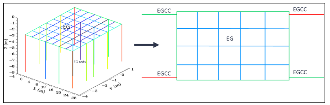
Figure 1 - A meshed underground earthing grid (UEG) with evenly spaced rods and no EGCC (left), and an UEG with 2 EGCCs at both sides of the UEG, with no vertical electrode (right)
In the application of Schwarz equations, the rectangular area on the ground as seen in (1), (2) and (3) and exemplified in Figure 1 (left), posits that 𝐴 = 𝐴2 = 𝐴𝑚. This is because the earthing rods are assumed to be evenly distributed across the rectangular meshed-loop but, most importantly, are vertically driven into the earth and therefore occupied the same grid area. In situations where the installation of rod(s) in the ground is impractical, the Schwarz engineering for the calculation of 𝑅𝑔 could still be applicable. For illustrative purpose, the Figure 1(right) shows where a rectangular UEG is designed, comprising of the main rectangular earthing conductor ring, its mesh with the EGCC conductors clamped at both sides of the UEG, and installed horizontally across its length at the same burial depth, ℎ as the UEG. The term earthing grid continuity conductor (i.e., EGCC) is used to represent a horizontal bare conductor usually connected or clamped to an underground earthing grid (UEG), to serve as a horizontal extension of the UEG for achieving desirable grounding specifications.
4.1. Schwarz Engineering
Schwarz in [1] developed the extension of the UEG equations to include combination with the rod(s), with the following understanding:
- that the shape of the UEG is ideally in rectangular ring form. An illustrative example is shown in Figure 1 (left).
- the meshing of the grid is done entirely within the rectangular ring. The meshing is used to further slightly reduce the 𝑅𝑔, by increasing the perimeter length of the earthing conductor from which the fault currents would have more least resistive -paths to the ground. One good reason for the vertical (width-side) meshing is to create a T-junction to enable easy clamping of the earthing rods to the earthing conductors. This could potentially reduce the step voltages at the ground surface.
- the combination of rods and their clamping to the grid-mesh ensures that a desired value of 𝑅𝑔 is achieved. Their effectiveness is mostly dependent on the soil resistivity and the spacing between the rods.
- that the added rods are meant to drive fault currents to the ground increasing the current gradient deeper into the ground, thereby reducing the EPR.
- the added rods with ground resistance of 𝑅2 occupies the same exact rectangular loop area, from which 𝐴 = 𝐴2 = 𝐴𝑚, is clearly observed.
- that the rods and the loop are buried at the same depth.
The dynamics of the above Schwarz UEG engineering could be extended with the following understanding:
- that the use of rods is mainly applied due to easy installation of rods farther into the ground, thereby ensuring a robust installation and earth contact.
- that the rods(s) which could be made from the recommended materials in [3], are applied to conduct fault currents down into the ground and could therefore maintain a safe EPR above the ground surface.
- that these rods can be replaced by good bare conductors (referred to as the EGCC), to still achieve the desired 𝑅𝑔 of the UEG.
- that these EGCCs does not necessarily need to be driven vertically within the same grid-mesh area but could be driven horizontally into the ground to create many least resistive current paths to earth, effectively reducing the 𝑅𝑔 and subsequently the EPR at the ground surface.
- that the materials used for the grid-mesh loop can also be used for the EGCC application. Furthermore, the bare conductors may be tinned to ensure protection against corrosive elements in the ground.
This paper demonstrates the application of EGCC in the design of UEG to aid in achieving the desired 𝑅𝑔 where combination of earthing rod(s) is either impractical or provides a huge installation difficulty or uncertainty, civil contingencies and/or a greater cost impact.
5. Earthing Grid Continuity Conductor (EGCC)
Earthing grid continuity conductor (EGCC) refers to a bare conductor clamped onto the main underground earthing grid (UEG) for the purpose of increasing the UEG coverage area and improving the effective ground resistance of the UEG. Some illustrative examples of UEG design configurations with EGCCs are shown in Figure 2, Figure 3, and Figure 4. The contribution of EGCCs to the grounding resistance of these UEG configurations are studied in section 6, with results tabulated in Table 1 and Table 2.
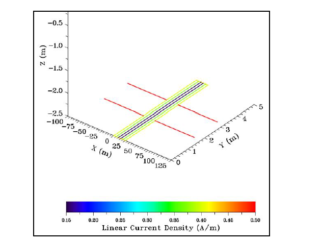
Figure 2 - Typical UEG's design layout for Table 1 in the FEM software with EGCCs connected of the width-side, showing the typical current density disparity between the meshed-loop and the EGCCs for this grid configuration
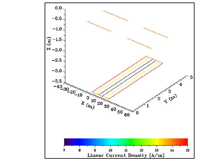
Figure 3 - Typical UEG design layout for Table 2 in the FEM software showing the typical current density disparity between the connected meshed-loop and the EGCCs for this grid configuration. Note: the EGCCs are directly buried at 1.1 m above the meshed-loop which is buried at 2.5m
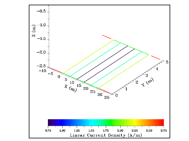
Figure 4 - Typical UEG's design layout for Table 1 in the FEM software (with EGCCs disconnected at the width-side and with 𝐷𝑒𝑔𝑐𝑐 = 1.8 𝑚 spacing), showing the typical current density disparity between the meshed-loop and the EGCCs for this grid configuration
5.1. EGCC Application
In situations, where the effective ground resistance of an UEG is above the desired value due to high to extreme-high soil resistivity in combination with installation difficulties or other limitations, the use of EGCC could be recommended to achieve the desired grounding resistance, especially in underground high-voltage cable transmissions and their applications. In the application of the EGCCs to the design of UEG from (1), (2) and (3), the condition of areas 𝐴 = 𝐴2 = 𝐴𝑚 is no longer valid. This is clearly due to the absence of rod(s) in the system dynamics, replacing them with the horizontal EGCCs. Secondly, the EGCC do occupy a certain area but may not be estimated as a rectangular loop due to its insignificant width contribution to the loop. As a result, the estimation of the 𝑅𝑒𝑔𝑐𝑐 could be done by transposing the physical area covered by the EGCC adapted from IEEE Std. 80-2013 for a bare earth electrode optimized for 𝑛 -number of parallel EGCCs on the following case scenarios:
5.1.1. The earthing meshed-loop and the EGCC are buried at the same depth/soil layer but with uniform horizontal spacing between them
When the earthing loop and the EGCCs are buried at the same depth (i.e., ℎ𝑒𝑔𝑐𝑐 = ℎ and 𝜌𝑒𝑔𝑐𝑐 = 𝜌 ) as shown in Figure 2 but with uniform horizontal spacing, 𝐷𝑒𝑔𝑐𝑐 between them, the ground resistance of the EGCCs is therefore given as,
(6)
where 𝜌𝑒𝑔𝑐𝑐 = 𝜌 is the soil resistivity (Ω.m), 𝐿𝑒𝑔𝑐𝑐 is the length of a single EGCC (m), 𝑛𝑒𝑔𝑐𝑐 is the number of EGCCs, and 𝑑𝑒𝑔𝑐𝑐 is the diameter of the EGCC (in m) with both the meshed-loop and EGCCs buried at the same depth [15]. Provided that the earthing bay has a very low electrical resistivity, the 𝑅𝑚𝑢𝑡, which represents the mutual ground resistance between the loop conductor(s) and group of parallel EGCCs can then be calculated from adapted Carson's empirical formula for mutual resistance given as,
(7)
where ℎ𝑒𝑔𝑐𝑐 = ℎ , burial depth of the EGCC(s) with 𝑛𝑒𝑔𝑐𝑐 = 4 recommended number of EGCCs, assumed to be uniformly spaced at the top and bottom of the loop width-edges. This uniform horizontal spacing (in m) between the EGCCs and the earthing loop is represented by 𝐷𝑒𝑔𝑐𝑐 in (7). This spacing is simply a transposition of gradient of the area covered by the grid loop and the area occupied by the EGCCs. The combined effective ground resistance, 𝑅𝑔 of the rodless UEG with the inclusion of EGCCs can therefore be given in two forms as 𝑅𝑔1, which is based on Schwarz, 𝑅1 and 𝑅𝑔2 which is based on Sverak, 𝑅𝑙𝑜𝑜𝑝 given as,
(8)
and
(9)
5.1.2. The earthing meshed-loop and the EGCC are tightly clamped together and buried at different depths/soil layers
When the earthing loop and the EGCCs are buried at different soil depths (i.e., ℎ𝑒𝑔𝑐𝑐 ≠ ℎ and 𝜌𝑒𝑔𝑐𝑐 ≠ ρ) since the meshed-loop is usually buried deeper than the EGCCs to simplify installation (i.e., ℎ𝑒𝑔𝑐𝑐 < ℎ), the grounding resistance of the EGCCs is therefore given as,
(10)
distributing the entire lengths of the EGCCs within the vertically traversal earth-depth as a giant spherical area, with EGCC burial-depth factor ζ = 𝐿𝑒𝑔𝑐𝑐/4πℎ𝑒𝑔𝑐𝑐. The mutual resistance is therefore given as,
(11)
where ρ𝑠 is the shallow-depth soil resistivity between the two layers with ρ and ρ𝑒𝑔𝑐𝑐. Here, ρ𝑠 = ρ𝑒𝑔𝑐𝑐 since ℎ > ℎ𝑒𝑔𝑐𝑐. The Equations (8) and (9) for the different burial-depth scenario, can consequently be adjusted to include the and
, respectively. This method is also applicable to an earthing system configuration comprising of tightly clamped meshed-loop and the EGCCs, buried at different soil depths but with a homogeneous soil, ρ = ρ𝑒𝑔𝑐𝑐.
In the subsequent sections, both analytical solutions in (8) and (9) and finite element method (FEM) would be used to calculate the 𝑅𝑔 of UEGs with five different ground resistivity conditions to create a better understanding of the EGCC approach. The impact of the uniform spacing 𝐷𝑒𝑔𝑐𝑐, for case scenario Section 5.1.1 would also be demonstrated.
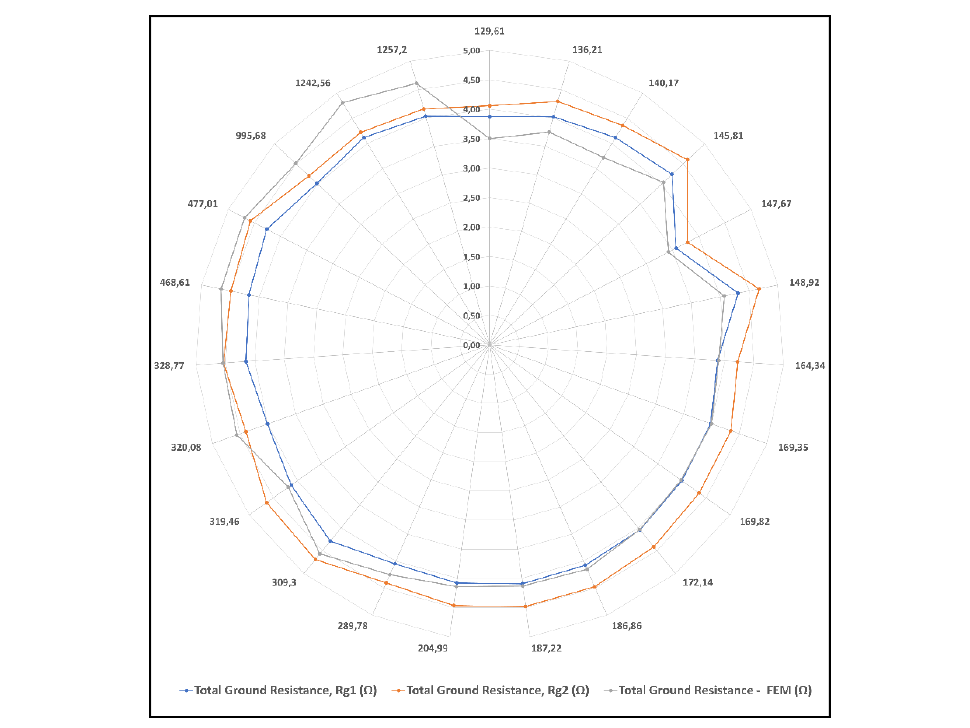
Figure 5 - Study scenarios 5.1.1 for 23 random samples of soil resistivity (in Ω.m) on a radar: results of realistic application of EGCC to the design of UEGs with uniformly-spaced EGCCs (see Figure 2), with spacing, 𝐷𝑒𝑔𝑐𝑐=1.75𝑚, ℎ𝑒𝑔𝑐𝑐=ℎ. The RMSE(𝑅𝑔1,𝑅𝑔−𝐹𝐸𝑀) = 0.85Ω while the RMSE(𝑅𝑔2,𝑅𝑔−𝐹𝐸𝑀)=0.47Ω. A target grounding resistance < 5Ω criterion is demonstrated in the vertical axis for the 23 random soil resistivity samples in the radar chart.
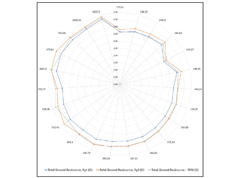
Figure 6 - Study scenarios 5.1.2 for 23 random samples of soil resistivity on a radar: results of realistic application of EGCC to the design of UEGs but with EGCCs uniformly-spaced and clamped/connected above the earthing loop (see Figure 3), with all EGCCs buried at 1.1m (i.e., ℎ𝑒𝑔𝑐𝑐≠ℎ) but at the same soil resistivity. The RMSE(𝑅𝑔1,𝑅𝑔−𝐹𝐸𝑀) = 0.84Ω while the RMSE(𝑅𝑔2,𝑅𝑔−𝐹𝐸𝑀)=0.36Ω. . A target grounding resistance < 5Ω criterion is demonstrated in the vertical axis for the 23 random soil resistivity samples in the radar chart
6. The impact of EGCC using both Analytical and Numerical Methods
Without diving into different methods of measuring multi-layer apparent soil resistivity, and advancing with the assumption of a single layer, these studies classify soil layers from low resistive ground, low-medium resistive ground, medium resistive ground, high resistive ground and very-high resistive ground. The analytical results of the impact of the EGCC would be comparatively estimated by both (8) and (9) analytical solutions and compared (and validated) by FEM simulations. The intensive studies involve the design of earthing systems, for grounds with varied soil resistivity conditions (23 random samples) ranging from low to high-resistive grounds, with a target grounding resistance of less than 5 Ω. The following assumptions and constants are made for these investigations:
- The rectangular grid loop is designed to be of length 24.5m (31.5m) and of width 5m (10m), all earthing design having each a 2 x 6 meshed-loop and a varied burial depth ranging from 2.25m to 4.30m. This is to show that the derived equations apply to realistic site pre-conditions, structural and civil-works possible adaptations.
- A tinned annealed bare copper conductor with a conductor diameter of 17.2mm is the material used for both the grid loop and the EGCCs. A minimum diameter of 11mm is calculated for annealed copper soft drawn conductor according to IEEE Std. 80-2013. Another study was done using the same material but with a 13.81mm diameter only for the EGCCs. These are to show that the methodology can be adapted to variable conductor sizes.
- The tinned conductor type is used to reduce interaction with corrosive elements in the soil.
- The values of 𝑘1 and (optimized) 𝑘2 factors are calculated according to [1].
- The soil resistivity is homogeneous across the entire area covered by both the earthing loop and the EGCCs.
- The fault duration for the FEM calculation is 200 ms.
The parameters above are used to ensure that the case study scenarios are comparable. Please note that in the absence of vertical earthing rods, the effectiveness of the horizontal and vertical conductors (forming the mesh-grids) in achieving a target grounding resistance as shown in Figure 1 is subtly negligible (mainly at earthing bays with soil resistivities above 120 Ω.𝑚). However, as the 𝐿𝑒𝑔𝑐𝑐 is getting shorter due to very-low resistive soil condition, the impact of the meshing becomes evident, since the transposed area occupied by the EGCCs become insignificant when compared to the area covered only by the meshed-loop. The grid-mesh is however very significant in reducing the body step and touch voltages. Moreover, in the design of earthing systems, priority should be given to the design method that guaranties the safety of personnel at the ground surface. Irrespective of the desired 𝑅𝑔, the limit of the EPR (or GPR) for safe design should also be considered to comply with the safety specifications according to EN 50522 standard. To further ensure the safety of working personnel, a body step current below the limit at which the possibility of ventricular fibrillation could occur described in IEC 60479-1 standard [16] should be considered. Although this is not within the intended scope of this paper, a few examples in this paper will show how increasing the lengths of EGCC impacts the grounding resistance of earthing systems and bring the touch and step voltages within permissible limits.
Earth Resistivity | Single EGCC length | Analytical-Rg1 | Analytical-Rg2 | ||
Ω.m | m | Ω | Ω | Ω | Ω |
200 | 14 | 4.04 | 4.47 | 4.24 | 4.01 |
600 | 85 | 4.15 | 4.42 | 4.76 | 4.50 |
1000 | 170 | 4.08 | 4.25 | 4.73 | 4.50 |
2000 | 400 | 4.39 | 4.50 | 4.69 | 4.52 |
4000 | 920 | 3.89 | 3.93 | 4.62 | 4.47 |
Earth Resistivity | Single EGCC length | Analytical-Rg1 | Analytical-Rg2 | |
Ω.m | m | Ω | Ω | Ω |
200 | 14 | 3.91 | 4.30 | 4.31 |
600 | 85 | 4.55 | 4.88 | 4.96 |
1000 | 170 | 4.72 | 4.96 | 4.97 |
2000 | 400 | 4.93 | 5.07 | 4.92 |
4000 | 920 | 5.01 | 5.09 | 4.90 |
6.1. Results and Findings with EGCC Application
The results of the EGCC application for the 5 case scenarios are presented in Table 1. It contains the case study ground conditions, the two analytical calculations, 𝑅𝑔1,𝑅𝑔2 and two FEM calculations, 𝑅𝑔𝑐𝑜𝑛, 𝑅𝑔𝑑𝑖𝑠𝑐𝑜𝑛 with variable spacing 𝐷𝑒𝑔𝑐𝑐 technique.
From Table 1, variable lengths of EGCCs are used to make the rodless UEG design for all case studies comparable to achieve an effective ground resistance below 5Ω. These studies are done for 28 random samples of ground resistivities, which are sufficient to make scientific investigations in Table 1, Table 2, Figure 5 and Figure 6. In general, they show that both analytical solutions of calculating the ground resistance of an earthing system (i.e., 𝑅𝑔1 and 𝑅𝑔2) at different configurations (i.e., EGCC spacing configuration with 𝐷𝑒𝑔𝑐𝑐) are similar to the same calculations using a finite element method (i.e., 𝑅𝑔𝑐𝑜𝑛 and 𝑅𝑔𝑑𝑖𝑠𝑐𝑜𝑛). The difference between the analytical solutions and the FE method lies within maximum thresholds of about ±0.5 for 𝑅𝑔2 and about ±0.85 for 𝑅𝑔1. To verify this difference, root mean square errors (RMSEs) between the two analytical solutions and FEM calculations are conducted given as,
(12)
where 𝑁 is the number of study samples. The RMSEs for the entire scenarios are shown in Table 3 and Table 4.
RSMEs |
|
|
Rg1 | 0.56 | 0.42 |
Rg2 | 0.50 | 0.46 |
RSMEs |
|
Rg1 | 0.27 |
Rg2 | 0.11 |
By combining the entire calculations, from low to very-high ground resistive study scenarios at both same and variable burial depths, it is observed that the maximum error is always at RMSE(𝑅𝑔1) = 0.85 Ω for 𝑅𝑔1 while that of 𝑅𝑔2 is at RMSE(𝑅𝑔2) = 0.5 Ω. These RMSEs are referred to as the error limit of the analytical solutions. This limit may have resulted from the FEM meshing of the EGCC laying positions within the UEG-design layout. For visualization purposes, an example plot of body-step voltage is shown in Figure 7. The maximum voltages are always observed in the areas covered by the EGCCs while the area covered by the earthing loop (which is the substation area) is almost at zero potential as shown in Figure 7. It is important to reiterate that these simulations show underground current conduction by EGCCs and not current conduction above the ground surface.
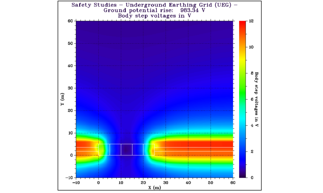
Figure 7 - Visualization of body step voltages for the UEG (i.e., 4 x EGCCs) design layout in Table 2 at the study scenario with 𝜌= 2000 𝛺.𝑚 and ground current 𝐼𝑔=200𝐴 using FEM software. The EGCCs are observed to be conducting the maximum ground voltages away from the Joint Bay, providing the least resistive part for current distribution
Having observed the feasibility of EGCC application in the design of UEG, there are certain findings to be noted in their applications, especially, at medium to very-high ground resistive conditions and/or longer EGCC lengths. These are that,
- the accuracy of 𝑅𝑔2 is consistent with its negligible error-limit in all applications. It is therefore recommended in the application of EGCCs for UEG design.
- the RMSE values accounts for the tolerance to be given in the analytical calculations using any of the 2 methods, with different laying conditions. For example, to design an UEG with a target grounding resistance, the analytical calculations of any proposed UEG design should be targeted towards achieving an 𝑅𝑔 with a maximum tolerance of about 0.85 Ω using 𝑅𝑔1 or 0.50 Ω using 𝑅𝑔2, to the target 𝑅𝑔 irrespective of the burial configuration/layout of the EGCCs around the meshed-loop as described in this paper. This is to ensure a complete conformity with most possible FEM meshing techniques.
- the analytical calculation of grounding resistance presented in Section 5.1.2 shows close conformity to the FEM solution. This is therefore recommended for use with 𝑅𝑔2.
- the analytical calculation of grounding resistance presented in Section 5.1.2 for different depths can also be employed in a direct crossing of the earthing loop by the EGCCs without the separation gap. In this case, the number of EGCCs becomes two instead of four. However, it is more advantageous to add these lengths to further optimize the 4 x EGCCs earthing grid design.
- the use of EGCC (in place of rods) will result to large use of EGCC conductor material for high to very-high resistive grounds and would require more burial area due to their lengths.
- the EGCC may unintentionally become the general ground current collector and conductor with high potential to transmit fault currents from other nearby or distant locations, thereby increasing the surface EPR at the joint bay or substation.
In addition, the EGCCs may also unintentionally intercept and conduct lightning-related currents including currents from nearby overhead-line grounding systems, nearby metallic structures, and/or direct lightning attachment to the ground. The possible effects of lightning-current distribution, transferred potential, and coupling into adjacent buried metallic systems should be considered in the grounding and bonding design. Even so, the possibilities of its application are undeniably the future of earthing system designs where the application of earthing rods is undesirable due to installation difficulties. A typical execution of this earthing grid system methodology in a high voltage cable joint bay is shown in Figure 8. This Figure 8 shows that the EGCCs, although buried at different depths as compared to the main earthing-loop, could also be laid along the same route of the cable transmission system, provided that the HV cables are protected inside high-density polyethylene ducts (usually with high electrical volume resistivity >1012 Ω.m) and the UEG design included the evaluation of electromagnetic interaction between the grounding conductors, surrounding earth conductivity, cable metallic screens and other metallic parts of the bonding systems.
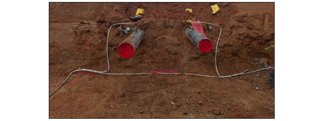
Figure 8 - Site execution of the grounding system design with grounding resistance calculated according to Section 5.1.2 methodology. Both the earthing loop and the EGCCs are buried at different depths
7. Substation safety: The impact of length of EGCCs on the body- voltages and currents
As we have seen so far in this paper, depending on the ground resistivity of the substation or joint bay, designing earthing grid systems with longer EGCCs than required continues to lower grounding resistances, thereby reducing the GPR at the substation. In Figure 7, we observe that the body step current above the ground surface is very small due to a relatively small ground fault current of 200 A. For high voltage transmissions, this value may be significantly higher. Ignoring all other solutions, including the use of high-resistive gravel layer at ground surface, used to improve the overall touch and step voltages, let us therefore estimate the step and touch voltages at an earthing bay (of area 24.5 ×5 𝑚) with a ground resistivity of ρ = 200 Ω.𝑚, estimating a maximum ground fault current, 𝐼𝑔 variations of 200 A, 500 A, or 1000 A, with a duration of 200 ms. Our aim is to investigate the impact of EGCC length on EPR, maximum body touch and step voltages according to EN 50522 [15] and IEC 60479-1:2018 standard on the effects of current on human-beings and livestock [16] as the magnitude of ground current varies.
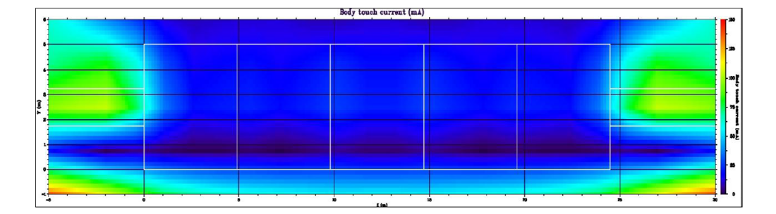
Figure 9 - Visualization of body touch current at ground surface of a joint bay (with length of EGCCs=28 m) according to Table 5, for a ground fault of 500 A. The maximum touch current is about 75 mA within the earthing joint bay.
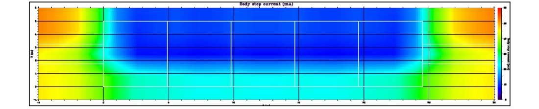
Figure 10 - Visualization of body step current at ground surface of a joint bay (the UEG is designed with lengths of EGCCs=28m for a grounding resistance of 𝑅𝑔=3.39 Ω) according to Table 5, for a ground fault of 500 A. The maximum body current of 60 mA is found at 5m proximity to the earthing joint bay.
Case A: UEG design with EGCC length of 14 m with | |||||
Ground current, Ig | EGCC length | Touch voltage | Step voltage | Touch current | Step current |
(A) | (m) | (V) | (V) | (mA) | (mA) |
200 | 14 | 82.37 | 31.07 | ≤ 60 | ≤ 25 |
500 | 14 | 205.84 | 77.67 | ≤ 105 | ≤ 55 |
1000 | 14 | 411.69 | 155.35 | ≤ 250 | ≤ 125 |
Case B: UEG design with EGCC length of 28 m with | |||||
Ground current, Ig | EGCC length | Touch voltage | Step voltage | Touch current | Step current |
(A) | (m) | (V) | (V) | (mA) | (mA) |
200 | 28 | 54.69 | 20.95 | ≤ 40 | ≤ 17 |
500 | 28 | 136.74 | 52.38 | ≤ 52 | ≤ 40 |
1000 | 28 | 273.48 | 104.77 | ≤ 150 | ≤ 80 |
For the purpose of this investigation, for a typical AC system, the design body model would be according to IEEE 80:2013 specifications, which include a body resistance of 1000 Ω. A value of 1000 Ω represents the resistance of a human body from hand-to-feet and from hand-to-hand, or from one foot to the other foot. This value is also the asymptotic value of body impedance for a current path hand-to-foot (i.e., for AC 50/60Hz) for large surface areas in contact with dry conditions (body impedance valid for 95% of the population) according to Figure 4 in IEC 60479-1 [16]. The result of this investigation is shown in Table 5, which illustrates the variation of maximum touch- and step voltages and currents at a given high voltage cable joint bay. By increasing only the length of the EGCCs, the touch and step voltages at the joint bay could be drastically reduced, even when the other proven reduction method as previously described in this paper and in IEEE 80:2013 were not included in the investigation. This is effective since by increasing the length of EGCCs, the grounding resistance is further reduced resulting in a reduction in the earth potential rise at the ground surface. Typical body-currents distribution, for example, are shown in Figure 9 and Figure 10, and tabulated in Table 5 for a ground current of 500 A, illustrating how the maximum body currents at the earthing bay (24.5 ×5 𝑚) were reduced from 105 mA and 55 mA to 52 mA and 40 mA, respectively. For HVDC systems, these values are within the DC-2 (i.e., 2 mA up to curve b) in IEC 60479-1:2018, which could only cause involuntary muscular contractions but usually with no harmful electrical physiological effects [16] for events that could result in such magnitude of ground current. In addition, for all the investigations, the body touch voltages are within permissible limit (i.e., with limit of 650 V for 200 < 𝑡 ≤500 𝑚𝑠 fault duration) according to DIN VDE 0845-6-1 standard [17], and EN 50522:2011 standard (with a limit of about 537 V for t = 200 ms fault duration) [15]. It is important to note that the magnitude of body voltages and currents are strongly dependent on the size of the area under consideration. The size of area considered in this paper are significantly larger than what is typically found in practice for the calculation of body voltages and currents. This practical consideration would significantly decrease these values, even at higher fault currents. It is crucial to note that the earth-return path should not be treated only as a static resistance to the reference earth since the applicable earth-return parameters may be frequency dependent as observed in CIGRÉ Technical Brochure 283 [18], and the frequency content of the fault or transient current should be considered when evaluating grounding conductor performance, transferred potential, and cable metallic screen/sheath interactions.
For HVDC systems, it is important to note that contingent faults and transients should be evaluated using a route - specific earthing system and the selected bonding technique studied alongside the DC-fault and overvoltage conditions addressed in relevant international standards, especially in IEC 62895 [19], CIGRÉ Technical Brochure 988 [20], and CIGRÉ Technical Brochure 852 [21]. This study should consider surface-potentials, EPR, touch voltage, step voltage, conductor-to-earth voltage, transferred potential, current distribution, corrosion or DC stray-current effects, and thermal withstand under the specified normal operation and disturbed condition of the HVDC system.
8. Summary and conclusion
In the design of an underground earthing system (for AC and DC applications) for the protection and safety of both personnel and equipment above the ground surface, priority should be given to any method that would ensure that the earth potential rise is kept at permissible safety level to avoid casualties or possibility of ventricular fibrillation, during transient contingencies. This means that ground currents should be driven farther into the local earth or away from the substation or joint bay in the case of EGCC application. This method is already analytically demonstrated by Schwarz and optimized by Sverak in IEEE Std. 80-2013 standard. This paper has shown that a similar engineering could also be applied where there are limitations of adding earthing rods to the earthing system design. Additionally, the methodology and analytical calculation of grounding resistance presented in Section 5.1.2 using 𝑅𝑔2 shows close conformity to all the FEM solutions and is therefore recommended for the analytical calculation of grounding resistance in the application of EGCCs at different burial depths with the meshed-loop. A low grounding resistance could still be guaranteed using the earthing grid continuity conductor (EGCC) in place of the earthing rods, even for realistic very-high ground resistive conditions. This method of earthing system design could find great applications in grounding system designs of underground HVAC and HVDC cable transmission systems for certain kinds of sheath bonding, especially for long power transmission lines and links. Currently, for ducted HVAC and HVDC cable transmission systems, EGCCs could conveniently be installed along the same route where the high voltage cables are buried, as previously shown in Figure 8, but with adequate studies and investigation on fault and ground current interactions with nearby metallic structures and their electromagnetic interactions with the cable system, as described in this paper.
In addition, higher ground resistivities necessitate UEG designs with longer EGCCs to achieve the desired effective ground resistance, 𝑅𝑔, permissible mesh (touch), and step voltages within the substation/joint bay area. This is also ideal for UEG designs at locations where there are land permit limitations since the EGCCs could also be routed along the same path as the HV cable system, especially for ducted cable systems, which has become common nowadays. In other applications, it could be possible to combine small lengths of EGCCs, with small number of earthing rods if found to be effective in that scenario and where possible. Future research in this area would include the creation of a new procedure (f.e., Wenner method or a new fall-off potential methodology), adapted from IEEE Std. 81-2012 [22], but required for the actual field measurement of the grounding resistance after the installation of the UEG design presented in this paper.
References
- S.J. Schwarz, "Analytical Expressions for the Resistance of Grounding Systems," Transactions of the American Institute of Electrical Engineers. Part III: Power Apparatus and Systems,, vol. 73, no. 13, part III-B, pp. 1011-1016, Jan. 1954.
- R. Rheinhold, "Grounding Principles and Practice I - Fundamentals considerations on ground currents," Electrical Engineering, vol. 64, no. 1, pp. 1-13, Jan. 1945.
- IEEE Standard 80-2013: IEEE Guide for Safety in AC Substation Grounding, IEEE, 2013.
- IEEE Standard 142-2007: IEEE Recommended Practice for Grounding of Industrial and Commercial Power Systems, IEEE, 2007.
- J.G. Sverak, "Optimized grounding grid design using variable spacing technique," in IEEE Transactions on Power Apparatus and Systems, , no. 1, Jan. , doi: 10.1109/T-PAS.1976.32113, vol. vol. 95, pp. pp. 362-374, 1976.
- BS 7430-Code of Practice For Protective Earthing of Electrical Installations, British Standards Institution, 2011.
- E.D. Sunde, Earth conduction effects in transmission systems, D. Van Nostrand Company, Inc. New York, 1949.
- M. Enrique, T. Oscar, R. Jorge and A. Alberto, "Two-layer soil model for power station grounding system calculation considering multilayer soil stratification," Electric Power Systems Research, vol. 37, no. 1, pp. 67-78, 1996.
- B. Dou, R. Liu, Y. Tu and B. Zhang, "A Method for Calculating Grounding Resistance of Reinforced Concrete Foundation Grounding Systems," Energies, vol. 15, no. 13, p. 4607, 2022.
- L. Siow Chun, G. Chandima and A.K. Mohd Zainal Abidin, "Electrical earthing in troubled environment," International Journal of Electrical Power & Energy Systems, vol. 47, pp. 117-128, 2013.
- Y. Khan, and F.R. Pazheri, N.H. Malik, A.A. Al-Arainy and M.I. Qureshi, "Novel approach of estimating grounding pit optimum dimensions in high resistivity soils," Electric Power Systems Research, vol. 92, pp. 145-154, 2012.
- M.N. Nor, R. Rajab, R. and Z. Othman, "Validation of the earth resistance formulae using computational and experimental methods for gas insulated sub-station (GIS)," International Journal of Electrical Power & Energy Systems, Elsevier BV, vol. 43, no. 1, pp. 290-294, 2012.
- M. Brenna, F. Foiadelli, M. Longo and D. Zaninelli, "Particular grounding systems analysis using FEM models," in 18th International Conference on Harmonics and Quality of Power (ICHQP), pp. 1-6, Ljubljana, 2018.
- C.L. Coelho, A. Piantini, H.A.D. Almaguer and R.A. Coelho, W.C. Boaventura and J.O.S. Paulino, "The influence of seasonal soil moisture on the behavior of soil resistivity and power distribution grounding systems," Electric Power Systems Research, vol. 118, pp. 76-82, 2015.
- UNE EN 50522: Earthing of power installations exceeding 1 kV a.c., 2022.
- IEC 60479-1:2018 Standard: Effects of current on human beings and livestock - Part 1: General aspects, IEC, 2018.
- DIN VDE 0845-6-1: Maßnahmen bei Beeinflussung von Telekommunikationsanlagen durch Starkstromanlagen – Teil 1: Grundlagen, Grenzwerte, Berechnungs- und Messverfahren, Verband der Elektrotechnik Elektronik Informationstechnik e.V., 2010.
- CIGRÉ, "Technical Brochure 283: Special bonding of high voltage power cables," 2005.
- IEC, "IEC 62895: High voltage direct current (HVDC) power transmission - Cables with extruded insulation and their accessories for rated voltages up to 320 kV for land applications - Test methods and requirements," 2017.
- CIGRÉ, "Technical Brochure 988: Surge and Extended Overvoltage Evaluation of HVDC Cable Systems for Testing," 2026.
- CIGRÉ , "Technical Brochure 852: Recommendations for testing DC extruded cable systems for power transmission at a rated voltage up to and including 800 kV," 2021.
- IEEE, "IEEE 81-2012: IEEE Guide for Measuring Earth Resistivity, Ground Impedance, and Earth Surface Potentials of a Grounding System," 2012.