Condition assessment of line composite insulators: after-service test programs and their practical application
AUTHORS
I. GUTMAN, J. LUNDENGÅRD, P. SIDENVALL - I2G, Sweden
A. DECKWERTH - 50Hertz, Germany
L. DIAZ - RTE, France
J.-F. GOFFINET - Elia, Belgium
K. HALSAN - Stattnet, Norway
M. LEONHARDSBERGER - APG, Austria
M. RADOSAVLJEVIC - SVK, Sweden
P. TRENZ - Bayernwerk, Germany
K. VARLI - Amprion, Germany
K. VÄLIMAA - Fingrid, Finland
M. HEATH - Transgrid, Australia
R. DAVEY, W. VOSLOO - Eskom, South Africa
Summary
At present line composite insulators are treated as a mature and reliable technology product, and it is estimated that more than 40 mln. of such insulators are already operating in service at transmission and distribution voltage levels. It is desirable that their service life would be comparable with traditional ceramic insulators. Possible ageing of composite insulators is a key issue that differentiates composite insulators from traditional ceramic insulators. Condition assessment of line composite insulators by after-service test programs including standard and non-standard test methods is the focus of this paper. The paper summarizes the findings from after-service investigations of 84 insulators including 10 different manufacturers representing Europe, Asia and America retrieved from operation on overhead lines of ten power utilities from Africa, Australia, and Europe.
keywords
composite insulator - condition assessment - hydrophobicity - after-service tests - pollution performance - ageing performance1. Introduction and goal
Application of line composite insulators started about 40 years ago and at present their fleet in service is estimated to be about 40 mln. insulators combining transmission and distribution voltage classes [1]. Three dominant reasons for their expanded application were derived from the answers to the specialized questionnaire obtained from 50 power utilities worldwide. These were handling, pollution, and price [1]. However, the existing fleet of composite insulators is very different for different utilities in the amount, application areas, time in service, typical designs, and chosen manufacturers, which is quite natural based on historical, environmental, and technical reasons for each individual utility.
A group of eight European power companies (both TSOs and DSOs) together with the Independent Insulation Group ( I²G, Sweden) are running a collaborative research project intended to benchmark composite insulators (2020-2023). The following companies support this project: 50Hertz (Germany), Amprion (Germany), APG (Austria), E.ON (Germany), Fingrid (Finland), RTE (France), Statnett (Norway), and Svenska kraftnät (Sweden). In the paper this R&D consortium is designated as “Europe”. Transgrid (Australia) together with I²G recently finished a project “Composite Insulator Testing” with similar program and goal. The data originating from this source is designated through the paper as “Australia”. ESKOM (South Africa) recently finished their own project with similar program and goal. This resulted in ESKOM technical report “Insulator Condition Assessment Required for Transmission Western Grid Line Re-insulation Projects” issued at the end of 2021. The data originating from this source is designated through the paper as “South Africa”.
Each of the three sources mentioned above includes information about many different types/designs of line composite insulators. This covers 7 manufacturers originated from European project, 4 manufacturers originated from Australian project and 3 manufacturers originated from South African project. Thus, the goal of this paper is to combine and analyze the results from different after-service test programs to evaluate pros and cons of different tests for condition assessment of composite insulators and propose an optimal matrix of tests.
2. State-of-the-art of after-service tests
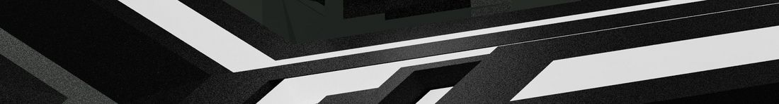
Only one CIGRE Technical Brochure (TB) published more than a decade ago is available for guidelines for assessment of composite insulators [2]. This TB provides a list of commonly applied test philosophies and test methods, see Fig. 1, followed by examples of six test programs contributed by the authors of the TB.
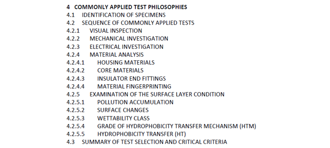
Figure 1 - Commonly applied test philosophies according to CIGRE TB 481 (2011) [2]
A broad variety of methods, philosophies and tools is described in the TB and no recommendation for optimal applications are given. It is recommended to perform the investigations in a specialized laboratory. An important innovation of the brochure is that critical ageing and damage criteria are defined for the first time. They are assumed to constitute the “end of life” of a composite insulator [2], and those are illustrated in Fig. 2.
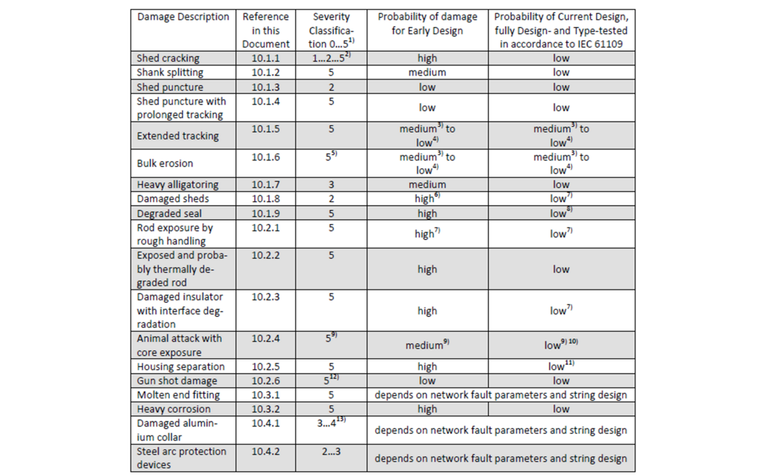
Figure 2 - Example of rating of damage according to CIGRE classification [2]
3. Test arrays and test programs
3.1. Insulators for the investigation
The complete list of investigated insulators is presented in Table 1. Eighty-four (84) insulators from this list were removed from the overhead lines (OHL) for the investigations. The collected test array covers many different parameters:
- Insulators made by ten different manufacturers (designated from “A” to “J”) from Europe, Asia, and USA.
- Different insulator designs such as standard, alternating and under-rib shed profiles, different designs of fittings and sealings, etc.
- Suspension and tension insulators.
- Different time in service (1-40 years).
- Different years of manufacturing (1981-2020).
- Different housing materials, i.e., High Temperature Vulcanized (HTV) silicone rubber, Liquid Silicone Rubber (LSR), and silicone rubber/EPDM alloy.
- Different voltage classes, i.e., Um between 145 and 525 kV.
- Different mechanical classes, i.e., SML between 120 and 600 kN.
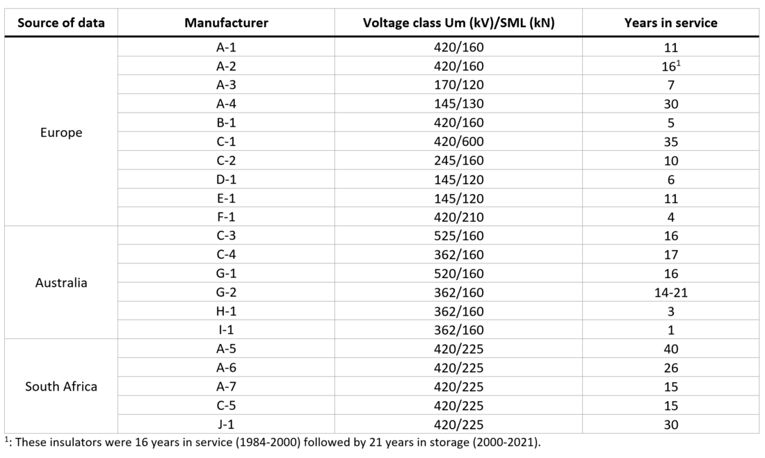
Table 1 - Summary of insulator test samples provided for testing by participating utilities
3.2. Test programs
The test programs used in the three different projects were slightly different and they are summarized in Table 2. A specific number of insulators was chosen for each type of test to cover as many different designs and important performance parameters as possible.
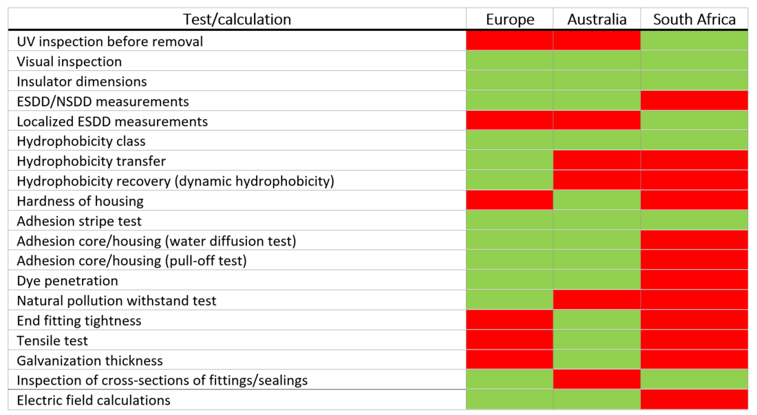
Table 2 - Test programs used in different projects. GREEN = applied; RED = not applied.

4. Test results
4.1. Electrical pollution performance
A list of tests for the estimation of electrical pollution performance includes:
- ESDD/NSDD measurements
- Localized ESDD measurements (similar to Apparent Salt Deposit Density, ASDD recommended by [2] and described in Section 4.2.4)
- Natural pollution withstand test
4.1.1. Different types of pollution measurements and results
In Europe and Australia, the ESDD (soluble part of contamination) as well as the NSDD (non-soluble part of contamination) were measured according to IEC 60815-1, annex C [3]. The ESDD/NSDD measurements were taken from the top and bottom of sheds along the insulator, see Fig.3, and then averaged. In South Africa the Localized ESDD measurements (LESDD) were applied, i.e., the insulator was gently wetted by water with a conductivity 7 µS/cm and the surface conductivity was measured at three locations along the insulator. The values were then averaged and converted into ESDD. This provides the Apparent Salt Deposit Density (ASDD) described in more detail in Section 4.2.4.

Figure 3 - Example of standard ESDD/NSDD measurements
To illustrate the results of pollution measurements, they are plotted in Fig. 4. For European and Australian data actual ESDD/NSDD are used making them directly comparable, while for South African data NSDD is decided as 0,1 mg/cm², which is a commonly used IEC value for light polluted areas. Also, ASDD measured in South Africa would be in general lower than standard ESDD.
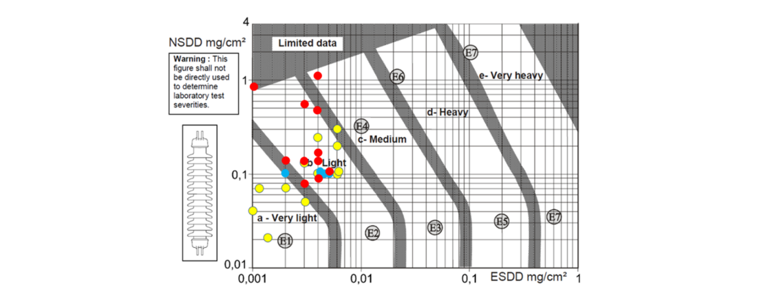
Figure 4 - Results of pollution measurements plotted on Site Pollution Severity classes graph for porcelain long rod insulators. YELLOW=Europe; RED=Australia; BLUE=South Africa
The figure adopted from IEC/TS 60815-1 [3] is formally for porcelain long rod insulators; thus, for composite insulators it can be used only as an indication. It was found that the results did not differ much depending on manufacturer or time in service. Basically, all measurements indicate that the insulators are in “Very Light” to “Light” Site Pollution Severity (SPS) classes according to IEC 60815-1 [3]. Using the creepage distance from the drawings, and the corresponding requirements in IEC/TS 60815-3 [4], all insulators were dimensioned for “Medium” or even “Heavy” SPS, providing a good margin in performance. It should be noted that IEC 60815-1 requires a minimum of 12 measurements per year for the establishment of the SPS; thus, the presented results are only indicative for such an evaluation and represent only a snapshot in time which does not take instantaneous pollution events in consideration.
This test is a must for any condition assessment of any insulators (ceramic or composite) because it allows to estimate the SPS influencing the service life.
Practical conclusion from this test for this paper is that it is possible to combine and analyze all results from three sources because the pollution conditions were similar.
4.1.2. Natural pollution withstand test
In the European project a special natural pollution withstand test was performed on eight insulators removed from service, see photographs of the test set-ups for 420 kV insulators (left) and 145 kV insulators (right) in Fig. 5. This test, recommended by CIGRE TB 691 [5] utilizes the so-called Modified Clean Fog Method. In this test the insulator is mounted in the operating working position and the voltage is applied with a large safety margin to the maximum operating voltage. In practice, reported tests performed with this method used a safety factor of 2,0 (with assumption that the pollution level reflects the actual level) and this safety factor was chosen as a target for the reported test. The insulators were installed in parallel in the large climate hall of STRI laboratory. An AC test voltage of 486 kV was applied for the 420 kV insulators, providing a safety factor of 2,0. Similarly, an AC test voltage of 186 kV was applied for the 145 kV insulators providing a safety factor of 2,2. Steam fog according to IEC 60507 was applied for 3 hours (in contrast to 100 min. for a standard test). Leakage current measurements were performed for all insulators. No corona/grading rings were installed in this test on any of the insulators, which additionally increases the electrical stress in the test.
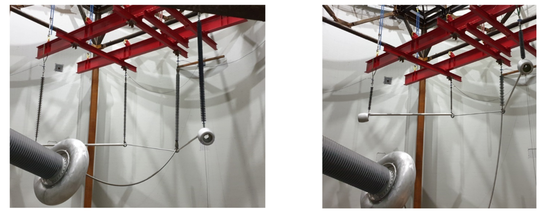
Figure 5 - Test set-up in the large climate hall of STRI HV laboratory. Left: 420 kV insulators, right: 145 kV insulators
Basically, the results are similar for all tested insulators. Despite very high level of test voltage applied, all insulators withstood the test with maximum leakage current far lower than needed to approach the pre-flashover mode (about 100 mA for low pollution levels). The actual currents were in the range of 0,6-16 mA.
Practical result from this test confirms that the insulators are dimensioned to withstand higher pollution than was measured in service. However, this rather expensive test may be omitted for the simpler “routine” condition assessment just comparing pollution measurements with insulator dimensioning as described in Section 4.1.1. To perform this test to get maximum possible information, one should consider obtaining the pollution performance curves for the insulators after natural ageing, and then to compare them to the curves for the same new non-aged insulators if available.
4.2. Electrical ageing performance
A list of tests/calculations for the estimation of electrical ageing performance includes:
- UV inspection before removal
- Visual inspection
- Hydrophobicity class
- Hydrophobicity transfer
- Hydrophobicity recovery (dynamic hydrophobicity)
- Hardness of housing
- Adhesion tests
- Dye penetration
- Inspection of cross-sections of fittings/sealings
- Galvanization thickness
- Electric field calculations
4.2.1 UV inspection before removal
The UV scans were obtained only in South Africa and only on some insulators which were later replaced based on the results of inspection and used for laboratory investigations. Examples of such scans are in Fig. 6. The observations from UV scans were correlated with the results of other investigations of the removed insulators, first of all, visual observations.
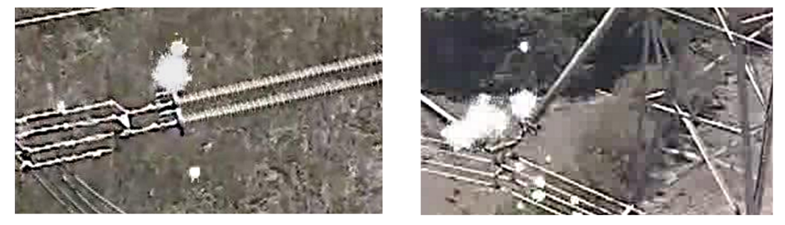
Figure 6 - Examples of UV scans of the insulators which were later removed from OHLs. Left: corona detected in the area where corona ring is in proximity of insulator shed due to corona ring misalignment; right: corona captured on the live (HV) side of the corona ring
This test can be used for the selection of insulators for the inspection. Permanent corona, especially in proximity of the housing, may in the long-term deteriorate silicone rubber. Performing in-service inspections comprising IR, UV, and visual imaging at the same time typically reveal most information about the insulators.
4.2.2. Visual inspection
Visual inspection is one of the most important tests in any of the after-service test programs. It provides unique basic data from naturally aged insulators and the suspected root cause for the deterioration may then be verified by additional tests. There are several internationally recognized guidelines available for the evaluation of visual inspection of composite insulators:
- CIGRE: Rating of damages is included in CIGRE TB 481 [2], see example in Fig. 2.
- STRI: Ranking of deterioration or damage is included in the Guide for visual inspections [6], see example in Fig. 7.
- EPRI: Guide for visual inspection [7], see example of ranking in Fig. 8.
- ESKOM: Chapter 11 from [8], see example of ranking in Fig. 9.
In Europe all three guides were used for the evaluation, while in Australia only the EPRI guide was used, while in South Africa, only the ESKOM guide which basically compiles the other three was used.
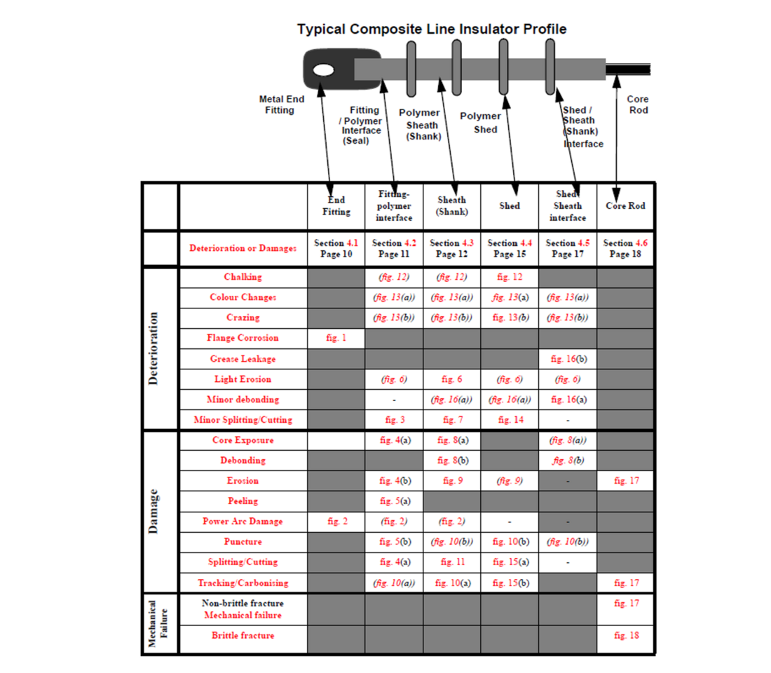
Figure 7 - Example of classification of deterioration/damage according to STRI Guide [6]
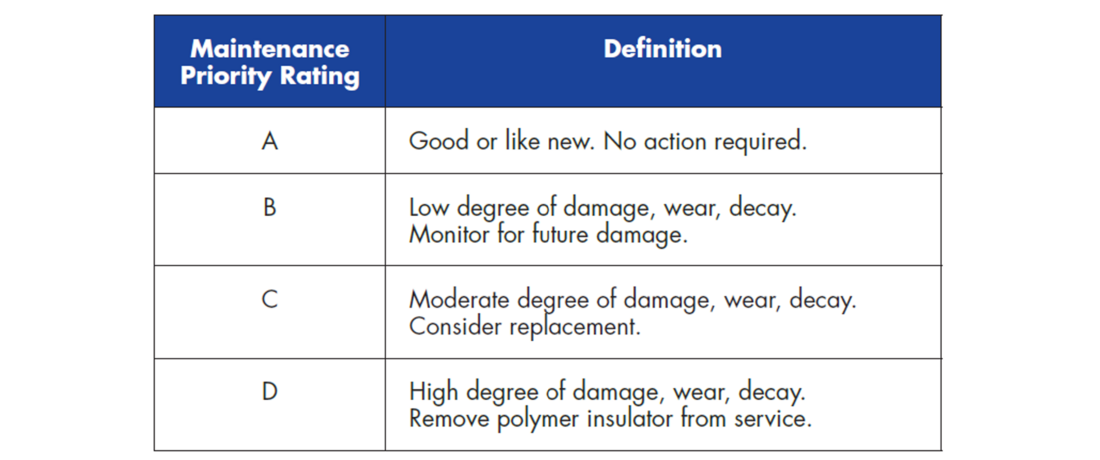
Figure 8 - Example of classification of deterioration/damage according to EPRI Guide (Maintenance Priority Rating) [7]
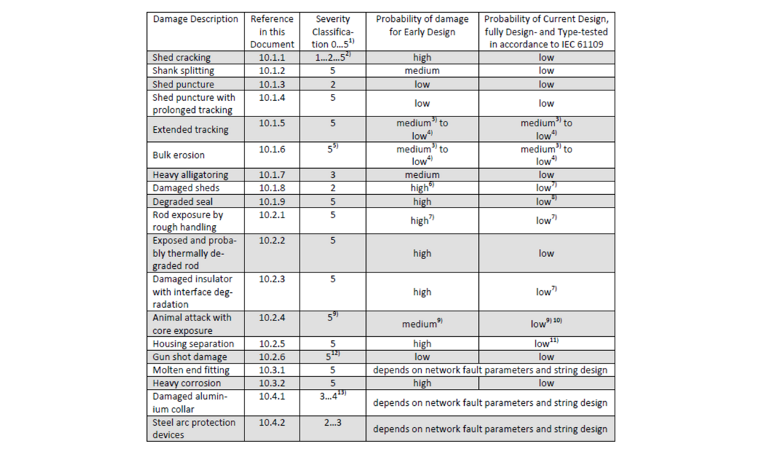
Figure 9 - Example of rating of damage according to ESKOM classification [8]
The results of the visual inspections from Europe are presented in Table 3 followed by several illustrations. The results presented in Table 3 are illustrated using a traffic light rating system, based on the three guides. In general, GREEN colour illustrates insulators without any danger for deterioration of their performance, YELLOW colour represents borderline cases, and RED colour displays that the insulation performance is seriously deteriorated. The detailed criteria used were as follows:
- For the CIGRE guide: in general, classes 1-3 are marked as GREEN, class 4 is marked as YELLOW, and class 5 would be marked as RED if available.
- For the STRI guide: any type of “Deterioration” is marked as YELLOW, and “Damage” is marked as RED.
- For the EPRI guide: Maintenance Priority Ranking (MPR) “A-B” is marked as GREEN (most of the observations), MPR “C” is marked by YELLOW and MPR “D” is marked by RED. Note that the MPR is only a recommendation provided by EPRI.
It is clear that the results are repeatable within the same batch (type, location, time in service) and all three guides provide approximately the same ranking.
Most of the deteriorations found in all three projects were of superficial character which confirms that there is no significant ageing of the housing material itself, even after up to 40 years in service. The types of deterioration typically included:
- Pollution including bird’s excrements
- Signs of surface leakage current activity
- Chalking (whitening of the surface)
- Biological growth
- Minor shed cracks
- Loss of hydrophobicity
- Traces of insects
- Paint drops
- Slight corrosion of end fittings.
Other types of deterioration found were as follows:
- Degradation of sealing of some insulators (different levels depending on design and environment)
- Handling and transportation damage revealed for all three projects and for the different European utilities. This requires a proper handling guide for composite insulators, it seems that the available CIGRE guide [9] or manufacturers recommendations are not enough.
- Corona-induced deterioration due to mistakes in dimensioning and location of corona/grading rings, revealed in all projects, examples are in Fig. 10. Intensive corona from metal was for Europe confirmed by electric field calculations (Fig. 11), while for South Africa this was confirmed by observations in service, Fig. 6. This observation calls for standard requirements for the optimization of grading/corona rings and this question is discussed more in detail in Section 4.2.11.
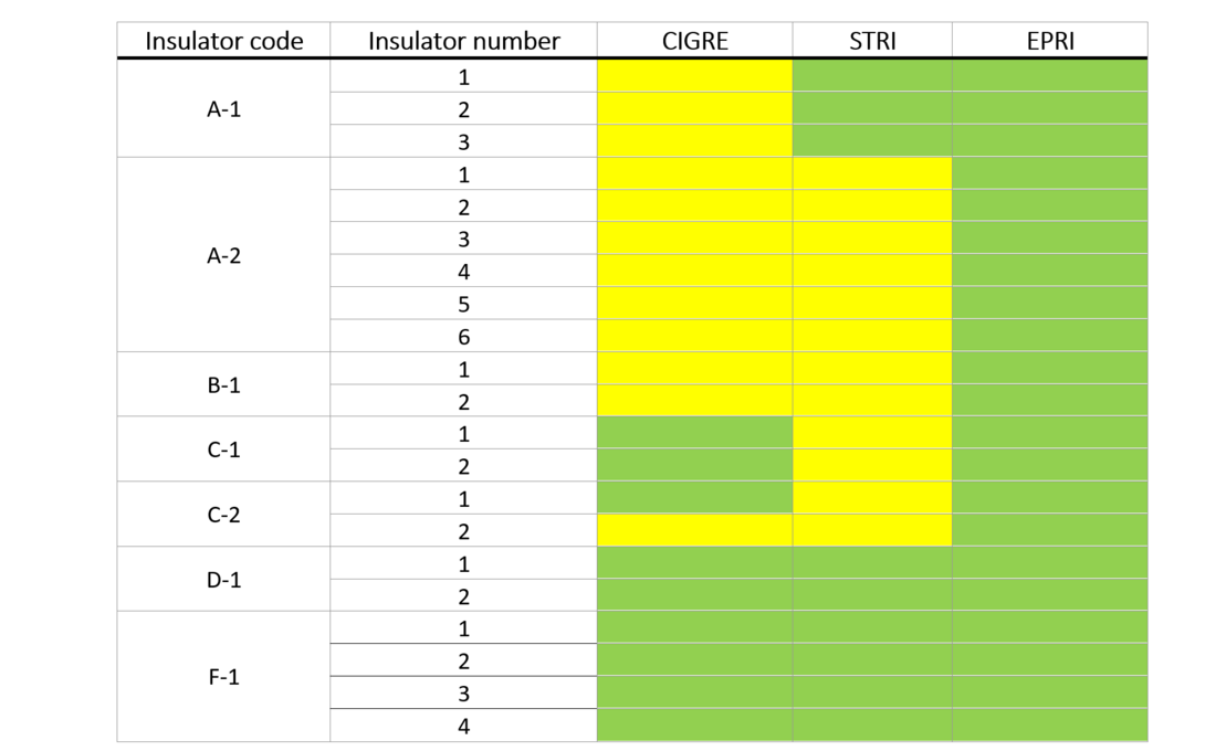
Table 3 - Summary of visual inspections in Europe evaluated using three different guides
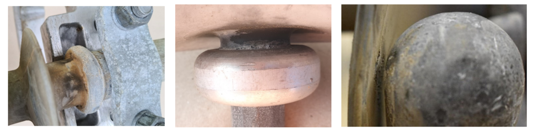
Figure 10 - Illustration of corona-induced deterioration. Left: example from Australia; middle: example from Europe, right: example from South Africa
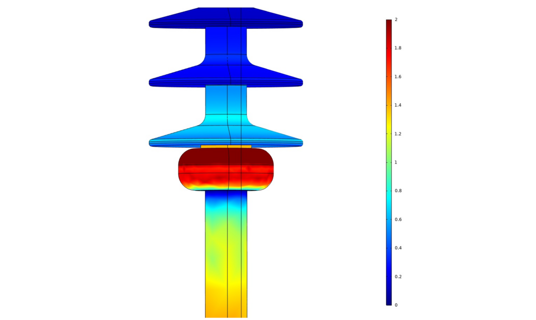
Figure 11 - Example of electric field calculations for the insulator presented in Fig. 10 (middle). Colour scale is 0-2 kV/mm. Dark red colour exceed 2 kV/mm; calculated maximum is 2,4 kV/mm. The results indicates that continuous corona can be expected
4.2.3. Hydrophobicity Class
The Hydrophobicity Class was evaluated using Method C (Spray Method) of the IEC 62073 [10]. This was done in identical way in all of the three projects. A spray bottle was used to produce a fine mist. The mist was applied from a distance of about 20 cm and the surface of the insulators was exposed to the mist for a period of 10 s to 20 s. Visual evaluation of hydrophobicity was performed within 10 s after spraying had been completed. The appearance of the insulator surface after mist exposure was identified with one of the seven Hydrophobicity Classes (HC), which has a value between 1 and 7; a surface with HC value 1 is the most hydrophobic, and a surface with HC value 7 is the most hydrophilic, the reference photographs are available in [10]. HC measurements are dependent on the experience of the observer. For an unexperienced observer, typical outputs would be “hydrophobic”, “hydrophilic” and “in between”.
The results are summarized in Fig. 12. The total average HC measured in different locations for each insulator type with similar time in service was calculated, and, as indicated in Fig. 12, the average hydrophobicity class reduces to a nearly hydrophilic state (HC 6) after approximately 10-25 years in service. Note that this estimation is purely indicative because the hydrophobicity is not completely and uniformly reduced along the whole length/surface on any of the insulators. Also, this parameter evaluates only the surface of the insulation material and does not indicate the degree of percolation of Low Molecular Weight (LMW) components/fluids from the bulk to the surface (hydrophobicity transfer capability).
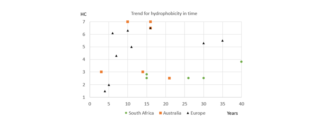
Figure 12 - Illustration of reduction of average hydrophobicity along the insulator with time in service as reflected by increasing Hydrophobicity Class (HC). Triangles: HC Europe; squares: HC Australia; circles: HC South Africa
This is a basic test and should be included in any after-service investigation. The results contribute to the evaluation of pollution performance of the insulator. For example, laboratory pollution curves in hydrophilic conditions can be corrected to the actual hydrophobicity level to verify the pollution dimensioning in time.
4.2.4. Hydrophobicity Transfer
This test was performed only in Europe. The Hydrophobicity Transfer (HT) measurements were performed according to the general recommendations of CIGRE TB 481 [2]. The HT is a measure of the ability of the material to recover the surface hydrophobicity through the pollution layer. The extent to which the hydrophobicity recovers through a pollution layer is normally defined as HT = (ESDD – ASDD)/ESDD, where ESDD is the pollution severity parameter measured according to IEC 60815-1, and ASDD is the Apparent Salt Deposit Density. The standard ESDD measurement procedure requires that all salts from the insulator surface are dissolved in water. This is done by wiping off the pollutants from the desired area by a squeezed cotton ball, repeated several times to ensure that all pollutants are removed. The pollutants are then dissolved by shaking and squeezing the cotton ball in the water. In contrast to the ESDD procedure, the ASDD is measured when only the non-embedded salts are dissolved, thus reflecting the pollution embedding effect of the LMW components. The ESDD level was measured after 5, 10 and 15 minutes. The ASDD level was considered as the ESDD level measured after 5 minutes, thereby representing natural salt dissolvent. After 5, 10 and 15 minutes, the insulator surface was scraped by a metallic tool and the water was stirred, bringing most of the encapsulated salts into solution. The HT level in this project was calculated as (ESDD10min-ASDD5min)/ESDD10min. The conductivity for ESDD calculations was measured using a special conductivity cell placed in contact with the insulator surface and filled with de-ionized water, see Fig. 13, left. The dynamics of ESDD in time is shown in Fig. 13, right.
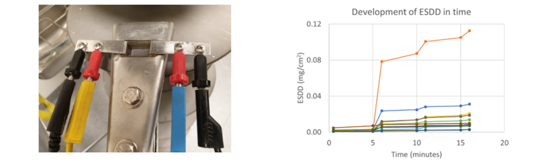
Figure 13 - Left: measurement cell used for the conductivity measurements. Right: illustration of development of ESDD over time during measurements in the cell (different colours correspond to different insulators/materials)
This method was applied to five “families” of different insulators made from the similar type of material. Similar method was applied earlier to these “families” obtained from the storage of participating utilities (but covering more insulators in each “family”). The results on insulators from service were only partially in line with earlier obtained results on these insulators and general insulators experience. It can be speculated that for extremely low levels of natural ESDD, as in our case, this test method might not be entirely applicable. The amount of salt is not enough to be dissolved, both on the surface and embedded. Thus, this method is not recommended as optimal, when the ESDD is below 0,01 mg/cm².
4.2.5. Hydrophobicity Recovery (Dynamic Hydrophobicity)
This method was applied only in Europe. The hydrophobicity recovery test (also referred to as dynamic hydrophobicity test) was performed according to [12], [13]; the only difference was that the samples were first gently cleaned from natural pollution. The idea of the test is as follows: LMW components, “responsible” for the material’s hydrophobicity properties, penetrate the pollution layer and encapsulate any salts found on the surface. The process gradually increases the electrical resistance of the pollution layer, even though the process of hydrophobicity recovery may not yet reach the top surface of the pollution layer. This is a typical behavior often seen on insulators in service in contaminated areas, confirmed by a combination of visual inspections and measurements. By measuring how the resistance increases with time, the recovery ability can be evaluated for different insulators.
Before testing, the samples were cleaned from natural pollution and dried. An artificial pollution layer was applied according to the principles of CIGRE TB 555 [14], i.e., pre-conditioning of the hydrophobic surface by dry kaolin followed by dipping in a suspension of kaolin, sodium chloride and water. The actual average value of the SDD/NSDD ratio for all tested samples was 0,06/0,12 mg/cm². This approximately corresponds to “Heavy” site pollution severity according to IEC 60815-1 for long rod porcelain insulators. The same suspension was used for all test samples, but due to different pollution susceptibility of the different materials, the actual levels of SDD/NSDD became slightly different. Thus, the results were compared in a normalized format, i.e., in relation to the individual starting resistance value of each sample. After application of contamination, the samples were left to dry and then placed in a closed chamber equipped with a humidifier for gentle moistening, see Fig. 14, left. The leakage current was measured between the electrodes on the moistened and polluted samples. The measurements were made after approximately 20 minutes of moistening, a period considered as sufficiently long to wet the pollution layer and short enough to prevent formation of drops leading to the pollution to be washed away. The leakage current was measured at seven instances during 168 h (7 days) of recovery time after application of pollution. The dynamics of resistance is illustrated in Fig. 14, right.
The ratio R168/R0, i.e., the final resistance divided by the start resistance, was proposed to rank the insulators. If R168/R0 is between 2 and 6, the recovery rate was considered acceptable (the material is still "alive"), and if R168/R0 is above 6, the recovery rate was considered very good [12].
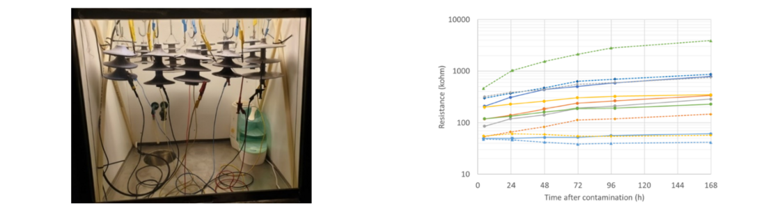
Figure 14 - Left: test set-up for the dynamic hydrophobicity test. Right: illustration of the development of resistance over time due to recovery of hydrophobicity for one of the test series. Different colour represents different insulator samples
The results are presented in Fig. 15, left in comparison to the results of identical test performed on brand new insulators from storage in Fig.15, right. The time-averaged results presented in Fig. 15 correspond very well with “general insulator knowledge”:
- It is known that HTV (High-Temperature Vulcanized) materials have a slightly lower speed of hydrophobicity recovery compared with LSR (Liquid Silicone Rubber) materials. In our results using R168/R0 this is approximately 3 against 6-8.
- The silicone rubber/EPDM alloy has low/no ability in recovering of hydrophobicity, and this is confirmed by test results (R168/R0 is about 1,0).
- Based on earlier experience with insulators of type C, these insulators might have a higher amount of filler in the silicone rubber, thus reducing the hydrophobicity properties. High filler content was used because of the earlier concern for the life of composite insulators related to tracking and erosion properties. Thus, large amounts of filler were needed to improve tracking and erosion performance by the cooling effect on partial discharges on the surface.
- The most important practical conclusion is that insulators made of HTV and LSR did not lose ability for recovering of hydrophobicity even after 30 years in service.
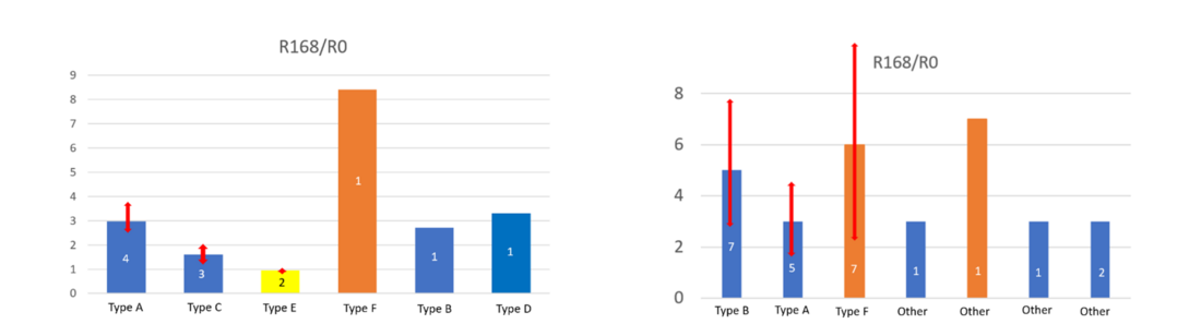
Figure 15 - Comparison of average hydrophobicity recovery rates for different insulator designs/materials (families). Blue bars indicate HTV housing materials, while orange bars indicate LSR housing materials and yellow bars indicate silicone rubber/EPDM alloy. Arrows show spread in results when at least 2 insulators from the same batch were available. Left: results for insulators removed from service. Right: results for brand new insulators from the same family
The proposed test better reflects actual service conditions by using contamination materials (kaolin and salt) as in the primary standard for pollution tests (IEC 60507). This test is highly recommended to be included in the optimal matrix of after-service tests. By doing this test on the same batch of insulators each 10-20 years, it is possible to follow the dynamics of the hydrophobicity, i.e., the actual level of deterioration of this key property. This test can be adapted for the evaluation of insulators after service.
4.2.6. Hardness of housing
This test was performed only in Australia. Hardness test was performed according to ISO 868 [15] (and IEC 62217 [16]) on samples before and after immersion of 100 h in boiling water. The measuring instrument, Shore A Durometer SAUTER Model HBA 100-0, is shown in Fig. 16. The average hardness after boiling should not differ from average value of non-boiled by more than ± 20 %. For each insulator sample 5 measurements on different positions were made and a mean value was determined. The temperature of samples and ambient was 21°C during the measurements.

Figure 16 - Example of measuring instrument type Shore A Durometer used in the test
All 13 insulators tested representing 4 manufactures passed the test with a large margin (0,2-3,8% comparing to the criterion 20%). This test, however, can be recommended for the optimal after-service test matrix. There are indications from service that some insulators became rigid and even brittle in time. However, this is normally indicated subjectively by touching the insulator. This was observed in some industrial environments. For such cases, the test will be useful to verify quantitatively possible surface degradation.
4.2.7. Adhesion tests
A stripe test was used in Australia and South Africa. The principles of the stripe test are described in [11]. In this test, two parallel cuts separated approximately 10 mm apart are first made through the rubber housing at the insulator shank. This can be done along the insulator or around the insulator circumference. The resulting stripe is thereafter pulled out from the underlaying fiberglass core using pliers, the knife tip or by hand. Adhesion is judged subjectively based on appearance of fracture. If the fracture occurs inside the rubber (cohesive failure), the adhesion is considered as adequate. If the fracture occurs along the interface between materials (adhesive failure), the adhesion is considered as inadequate. This test was considered for application as a screening test to characterize preliminary the level of adhesion of the test sample. This is because the sensitivity of the test allows to reveal only very weak adhesion core/housing. The stripe test performed in the Australian project revealed poor core/housing adhesion only for insulator H-1, while missing the poor adhesion for insulator I-1. However, for both of them poor adhesion was very clearly revealed by more sophisticated testing described below (see Table 4). At the same time, ESKOM used stripe test with success for the insulators with weak adhesion. The bonding core/housing appeared to be non-uniform, which resulted in punctures of the housing starting from the HV side and going up to approximately a third of the insulator length.
More sophisticated tests were performed in Europe and Australia. This test has become internationally recognized and has been presented to various CIGRE and IEC working groups; the detailed description of this test can be found in [12], [17]. The proposed test procedure fulfils formal IEC requirements for any new test, i.e., representativity, repeatability, reproducibility, and cost-effectiveness. Specimens about 30 mm in length comprise the core and housing, including one shed. The water diffusion test includes 100 hours of boiling (pre-stressing) followed by current measurements (see Fig. 17, left) and by a mechanical pull-off test (see Fig. 17, right). Three samples per insulator (top/middle/bottom) are used for the water diffusion test, and 12 measuring points per insulator are subject to the pull-off test. The criteria for passing the water diffusion part of the test are that no puncture or surface flashover should occur and that the current is below 0,1 mA for any measurement on the same insulator (the criterion for the current is accepted for the revision of IEC standards for solid core insulators). The criterion for passing the pull-off test is that the average stress per insulator is above 1,5 N/mm².
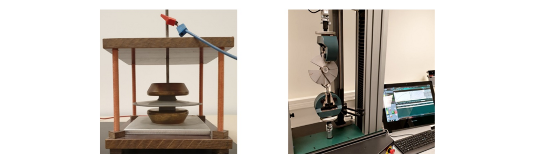
Figure 17 - Illustration of set-ups for adhesion test. Left: for current measurements after 100 h of boiling; right: for the pull-off test made with a standard tensile test machine
Application of the current measurements to the samples with natural pollution and some deterioration of surface required additional modification. For a typical sample, as in Fig. 17 (left), a few parallel current paths are theoretically possible during the measurements:
- Along the interface core/housing, which is our primary concern and the main goal of the measurements.
- Through the core itself, which might be possible if the core is of poor quality. Therefore, the IEC WG revising IEC 62217 agreed to have the same criterion (< 0,1 mA) for the naked core as for the sample comprising a core with housing (as in our case).
- Along the outer surface of the housing. To prevent this, we originally proposed test samples incorporating a shed.
- Through the housing material.
For some insulators very high currents in the range from 2 mA to 13 mA were obtained after 100 h of boiling while application of about 12 kV during 1 min. Considering such extreme test stress as boiling, and that the test voltage stress is minimum 30% higher than in service, no such effect is expected to be revealed in service. However, in contradiction to the earlier results for new insulators, the results of the pull-off tests after boiling for the same samples were either above the criterion or at the borderline. If the core/housing adhesion is weak, such level of currents may lead to the puncture of the interface, however, no punctures were observed for any of samples tested. It was suspected that, in this case, the main portion of the current went along the surface of the housing, and not through the interface. Therefore, a series of additional tests were performed:
- Standard test sample
- Sample after chopping off a part of the shed
- Sample after removal of the top layer of the rubber (Fig. 18, right)
- Standard test sample equipped with guarded electrode to divert the current along the housing (Fig. 18, left). The guard electrode was made by wrapping two laps of a thin copper wire around the trunk about 10 mm above the lower (grounded) end of the test sample. To avoid contact with the end electrode, a piece of rubber was used to cover the protruding wire.
The last modification comprising a guarded electrode was finally considered as the best option to improve the test method for naturally polluted insulators. The results obtained for insulator Type C were well correlated with microcracks in the top layer of the material, which was also confirmed by dry band formation (Europe). Similar type of microcracking, leading to currents along the housing was also obtained in Australia.
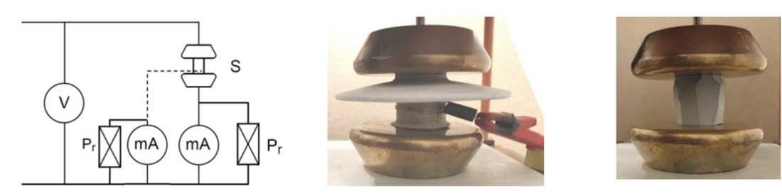
Figure 18 - Left: scheme of electrical connections for the test with/without guard electrode; middle: example of special guard electrode used to measure the current along the housing; right: example of sample with removed top layer of rubber
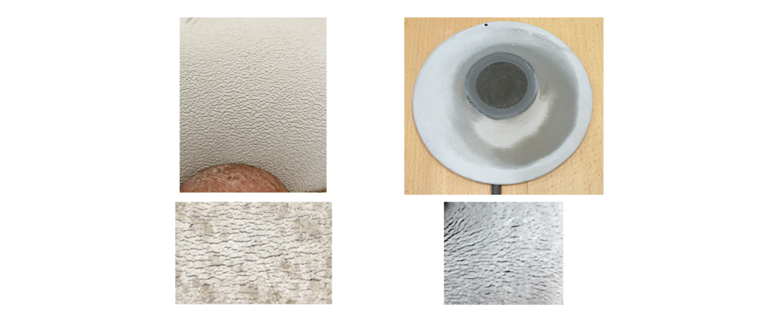
Figure 19 - Top-left: example of microcracks in the top layer of insulator type C from Europe; top-right: dry band at the surface of housing of the same insulator as a result of current of 3-10 mA. Bottom: examples of microcracks in the top layer of insulator type C leading to the current along the housing from Australia
Core/housing adhesion is one of the key parameters for the long-term performance of composite insulators. Scientifically interesting results were obtained by application of water diffusion test for insulators from service with different quality of a few components (core, interface core/housing, housing). Detailed analysis made it possible to explain results and sort them into relevant or irrelevant categories with respect to core/housing adhesion. The results are illustrated in Table 4 using traffic light principles (GREEN colour illustrates insulators which passed the test, YELLOW colour illustrates borderline cases, and RED colour illustrates that an insulator did not pass the test). A new additional criterion was used for better visualization of clusters in adhesion properties, namely the average force in the pull-of test divided by the average current in the water diffusion test. For an insulator fulfilling both criteria, the new criterion becomes 1,5/0,1=15. Other illustrative results are presented in Fig. 20 adopted as an example from [12] for new insulators from storage, but for different designs and batches. Accumulating such clusters for each specific manufacturer for new and aged insulators, and exchanging the results with other power utilities, makes it possible to keep track of manufacturers' quality control of this important functional property of the insulator.
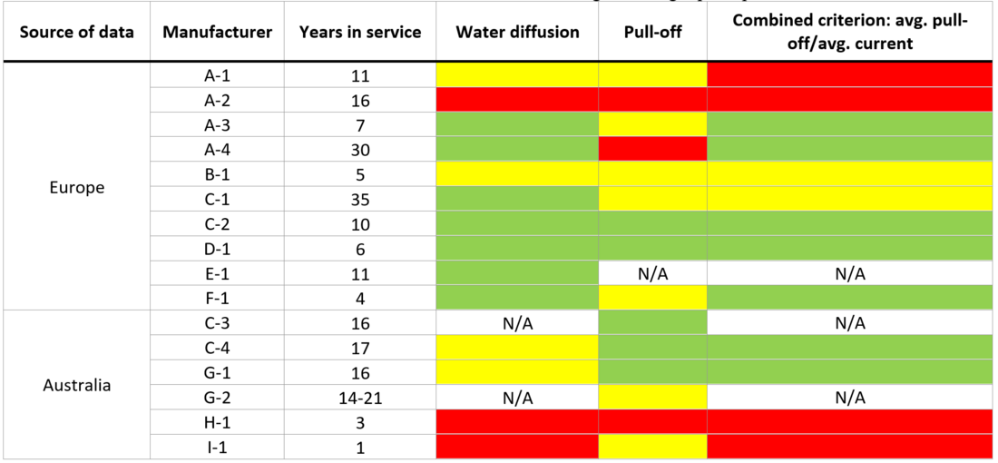
Table 4 - Illustration of adhesion test results using traffic light principles
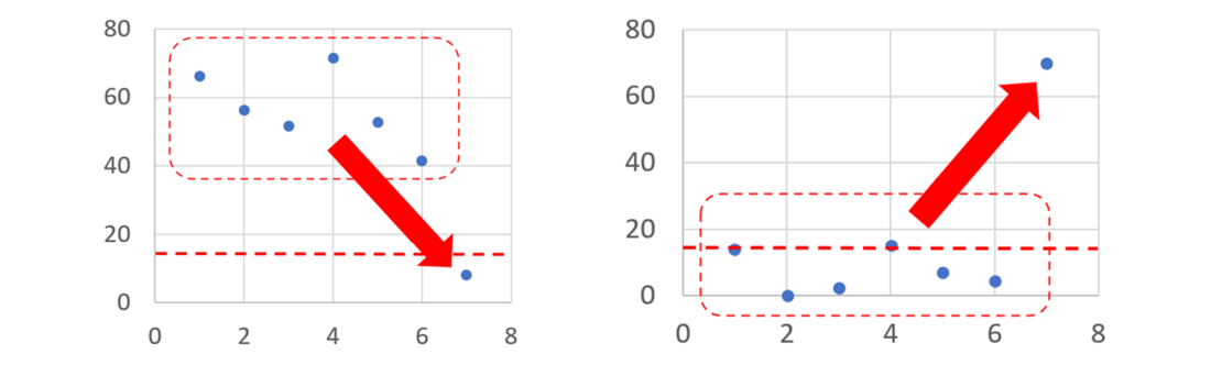
Figure 20 - Illustration of adhesion clusters for different manufacturers based on the new additional criterion of average force in pull-of test divided by average current in water diffusion test. Dashed lines show the criterion 1,5/0,1=15. Left: designs with a generally high level of adhesion. Right: designs with a generally low level of adhesion. Adopted from [12]
4.2.8. Dye penetration
This test was performed only in Australia. The dye penetration test on the core, also called the porosity test, was performed according to IEC 62217 (clause 9.4.1) [16]. Basically, the samples are immersed to a depth of 2-3 mm in the standard dye penetrant liquid for 15 min before visual inspection. This test was performed on one insulator per type with a minimum of 10 samples (each 10 mm long) were taken from different parts of each insulator. A photograph of the test container with 10 samples is shown in Fig. 21, left. The requirement for passing the test is that no penetration of the core occurs during the 15 minutes. In our tests, samples with housing were used, which is allowed by [16]. Only one type of insulators did not pass the test, while all others passed. This is normally a rather rare type of defect, which may in the long run lead to internal breakdown in the core followed by mechanical failure and thus should be further investigated. Thus, in addition to the above presented tests, ten 30 mm long samples from the same insulators were subjected to a 1,5 h test (instead of 15 min). No dye penetration was observed which indicate that the defect might be limited to only certain portions of the core.
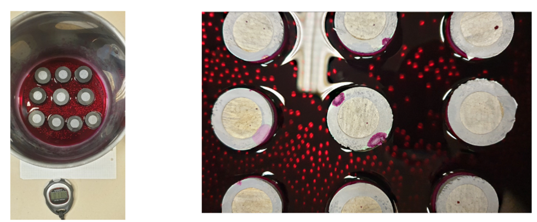
Figure 21 - Left: illustration of set-up for dye penetration test for 10 samples. Right: illustration of the results of dye penetration test for one insulator, which did not pass the test (points of penetrated dye are visible on all samples)
4.2.9. Inspection of cross-sections of fittings/sealings
This was performed in Europe and South Africa. In Europe, one end fitting of each type of insulator was cut open using an angle grinder. An example of the cross-section is presented in Fig. 22. No visible deterioration was revealed for any of the insulators. At present, there is no reliable standard or non-standard tests to evaluate the quality of the different sealing methods. This issue became the driving force of a separate research project intended to summarize the up-to-date knowledge of the different designs of fittings/sealings and to propose and verify innovative test methods for evaluating the integrity of the sealing. The results of the project are summarized in [18], and it was found that the complexity of the sealing design does not necessarily improve the performance [18]. An interesting option to verify further would be the corrosion and saltwater boiling test proposed in [18], which seems to be a promising scanning test for a quick evaluation of the sealing.
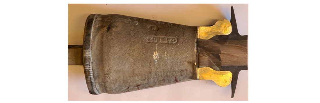
Figure 22 - Example of dissected end fitting
Differently to the positive results above, ESKOM confirmed the root cause of damage found at one of their insulators using the dissection, which showed that there is a rod/housing bond problem. The bonding appeared to be non-uniform especially in the sheath/end fitting junction point. Also, dissection of the end fitting showed signs of moisture ingress, indicating the start of the end fitting seal failure.
Thus, such test is recommended to be included in the optimal matrix for after-service tests.
4.2.10. Galvanization thickness
This was performed only in Australia. Galvanization thickness is evaluated by the galvanizing test according to IEC 60383-1 (clause 26) [19]. Basically, this test includes visual inspection followed by determination of the coating mass by the magnetic test method (see illustration of practical measurements in Fig. 23). This test was performed on 39 insulators, comprising 1170 measuring points in total (for each insulator three series of consequent measurements were made, each comprising ten individual measurements on different parts of the fittings).
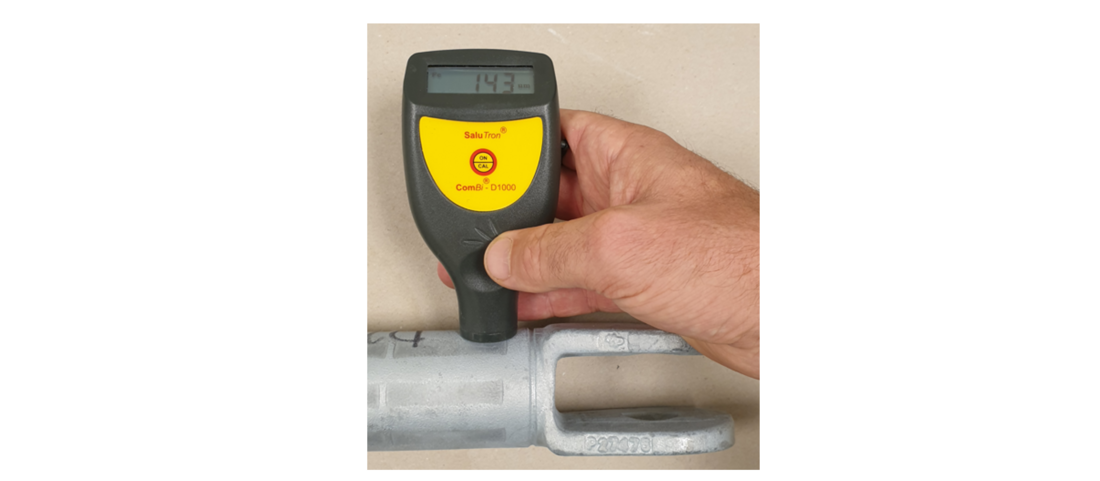
Figure 23 - Illustration of measurement of coating mass of galvanization by magnetic test method
The acceptance criteria for galvanized coatings were according to Australian/New Zealand standard [20], i.e., the minimum thickness is specified as 70 mm and average thickness as 85 mm. There were no visual deviations on any of the insulators and only 1 of 1170 measurements was slightly lower than the criterion (minimum 65 mm).
Thus, this test can be omitted from the optimal matrix for after-service tests.
4.2.11. Electric field calculations
These calculations were performed in Europe and Australia. Electric field calculations were performed for the three insulators equipped with actual arcing horns/grading rings delivered by Transgrid together with the insulators. Three criteria were used for the evaluation of the grading arrangements [21]:
- The E-field strength on grading rings and end fittings should not exceed 1,8 kV/mm.
- The average E-field strength along the housing surface should not exceed 0,42 kV/mm.
- The E-field strength at the triple point, where air and housing meet the metallic end fitting, should not exceed 0,35 kV/mm.
The first criterion is applicable to metal fittings at the HV end and at the grounded end of the insulator in dry conditions. The second and the third criteria are applicable to the housing material. The criteria correspond to electric field strengths in dry conditions; however, the criteria are derived from results of water drop induced corona tests in wet conditions. All calculations were performed using Comsol Multiphysics 5.6 software [22]. Modelling of actual insulators was made using their detailed drawings or measurements. Bundle configuration and conductor dimensions were provided by participating utilities. The towers were also modelled using drawings or photographs. The 3D electric field calculations were performed for the phase having the highest electric field stress, in order to simulate a worst-case scenario from electric field point of view.
Only six to eight sheds (or shed pairs in case of alternating profile) at the HV end of the insulator were normally modelled. This simplification is based on I²G’s earlier experience with similar calculations, where it was shown that only a few sheds close to the insulator fittings are exposed to the highest electric field levels [21]. By this simplification, the modelling time is reduced without affecting the results. The potential of phase conductors and connected metal hardware were set to values corresponding to the maximum system voltage. The potential of the tower structure, ground surface, insulator upper (grounded) end fitting, and shield wires, were set to zero. If the arcing horn/grading ring arrangement was not symmetric, the electric field stress was evaluated on both sides around the insulator and the highest values were used. All permittivity values used for the insulating materials are shown in Table 5.
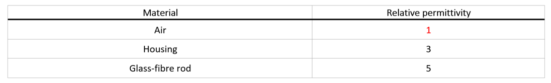
Table 5 - The relative permittivity values of materials used in the calculations
In general, the calculations covered the following:
- the absolute electric field stress on the surface of the arcing horn/grading ring,
- the absolute electric field stress on the surface of the end fitting,
- the tangential electric field stress along the insulator housing surface at the HV end, and
- the tangential electric field stress at the triple point (sealing/air/end fitting).
Typical results of calculations from Europe are presented for illustration in Fig. 24.
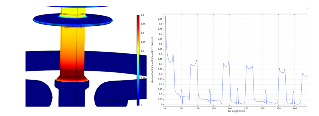
Figure 24 - Example of results obtained from the electric field calculations for the insulator with improper grading. Left: tangential field stress at HV end, colour scale 0 – 0,5 kV/mm. Right: tangential electric field stress along the surface of the housing, scale 0 – 0,9 kV/mm
In the Australian project analysis of visual deterioration revealed that for some insulators deterioration is likely related to excessively high electrical field strength. It was thus decided to make electric field calculations on three insulators where this was found. The main criterion was possible water-induced corona, i.e., Emax values averaged along any 10 mm of housing surface. In two cases the criterion <0,42 kV/mm was exceeded (0,6 kV/mm) and in one case, it was at borderline (0,40 kV/mm). These results indicate that some of the manufacturers are not aware of the proposed and internationally disseminated criteria. The results of predicted water-induced corona are also in line with the field observations. The insulator presented in Fig. 25 is formally accepted from electric field point of view (borderline case 0,40 kV/mm). However, traces from discharge activity were clearly visible on this insulator after only two years in service. Despite the short service period, this insulator became hydrophilic. This can explain the traces of discharge activity because it was shown in [23] that reduction of hydrophobicity results in lower inception levels of corona. The appearance of corona could be most probably revealed by UV inspection in service.

Figure 25 - Example of traces of discharge activity, might have been accelerated by borderline level of electric field strength combined with hydrophilic state of this part of the insulator
In the European project the calculations were performed for eight insulator types. The main criterion was again possible water droplet-induced corona. It was found that three insulators were fully in line with the criterion, three needed slight adjustment of grading rings (50-100 mm up in comparison to present position) and two did not fulfil the criterion (0,7-1,0 kV/mm > 0,42 kV/mm). Two last insulators did not fulfil the criterion for triple point either (1,4-2,3 kV/mm > 0,35 kV/mm). This was explained by the absence of grading rings in one case and old design of the protection hardware in the second case. The results of the electric field calculations led to assumption that in general most of the manufacturers producing insulators at present are aware of the proposed and internationally disseminated criteria, despite that they are not yet prescribed by IEC. As shown in [21], only 12% of the investigated new insulators (26 in total) need small adjustments of the position of grading rings to avoid water drop induced corona (normally 2-10 cm up), and only 4% of the insulators (1 of 26) has too high electric field stress at the triple point.
This calculation is recommended for the insulators where visual deterioration due to corona is revealed or is suspected from general insulator knowledge.
4.3. Mechanical performance
A list of tests for the estimation of mechanical performance includes:
- End fitting tightness
- Tensile test
4.3.1. End fitting tightness
This test was performed only in Australia according to IEC 61109 (clause 12.4a) [24], where it is called “Tightness of the interface between end fittings and insulator housing”. Basically, the insulator is subjected to crack indication by dye penetration after application of mechanical stress of 70% of SML. A typical force-time diagram at testing of an insulator with SML 160 kN is presented in Fig. 26.
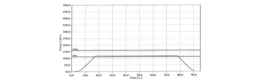
Figure 26 - Example of force-time diagram for insulator with SML 160 kN
All 13 insulators passed the test, and this test is not recommended for optimal after-service test matrix.
4.3.2. Tensile test
This test was also performed only in Australia according to IEC 61109 (clause 12.4b) [24]. In this test, the evaluated insulator is subjected to mechanical stress of 100% of SML followed by a load increase until failing load is reached. An illustration of typical force-time diagram for insulator with SML 160 kN is presented in Fig. 27.
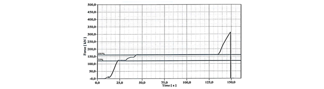
Figure 27 - Example of force-time diagram for insulator with SML 160 kN
According to IEC 61109 (clause 12.4b) [24] the criteria to pass this test include both the results of tensile strength and tightness of end fittings. The tightness was good for all insulators tested (see Section 4.3.1). For the tensile strength, all insulators passed the test at 100% SML and their failing loads are characterized by large margins to the SML (40-100% higher). Such large margins were typical for the insulators of the earlier generations, see example in Fig. 28 of similar tests made on Russian-manufactured insulators after up to 10 years in service (the average margin is 50%) [25]. At that time manufacturers were not sure about the long-term mechanical performance and thus used such high margins, while at present this factor is normally 15-20% (this is based on private discussions with several manufacturers). Reduction of the safety factor is based on improved technology and, especially, better quality control than for the earlier generations of insulators.
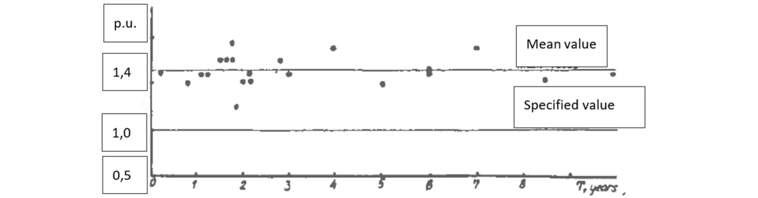
Figure 28 - Result of after-service mechanical tests of Russian-manufactured line composite insulators after 0,3-10 years in service. The mean value was 1,5 p.u. Specified value was 1 p.u. =SML [25]
All 13 insulators passed the test, and this test is not recommended for optimal after-service test matrix.
5. Discussion
5.1. Practical application of test results
The test programs for after-service tests were used further in all three projects for condition assessment of insulators in question followed by recommendations for maintenance actions.
An example of output summary of the condition assessment for all tested insulators in Australia considering specific criteria for each of the parameters is presented in Fig. 29. The results were extrapolated for the whole batch of insulators from the same tower. The following abbreviations are used:
- Vis = Visual inspection
- G = Galvanization thickness
- Ha = Hardness of housing
- HC = Hydrophobicity of housing
- PO = Pollution
- T = Tensile strength
- ST = Safety factor (failing load/SML)
- TI = Tightness of end fitting
- D = Dye penetration in the core
- S = Stripe test
- WD = Water diffusion test
- PU = Pull-off test
- E = electric field calculations.
For this condition assessment/benchmarking, the following parameters are evaluated:
- Ageing parameters (visual inspection, hardness of housing, galvanization thickness, mechanical performance).
- Pollution parameters (level of pollution).
- Choice of material considering dynamics of hydrophobicity (Hydrophilicity Class).
- Quality of adhesion (stripe, water diffusion, pull-off). This parameter is treated as the most important, thus providing up to three order of merit points.
- Manufacturer’s knowledge regarding control of the electric field in sensitive areas (E).
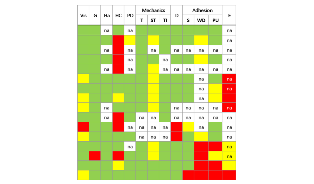
Figure 29 - Example of summary of condition assessment of composite insulators in Australia
A similar output summary of the condition assessments for all tested insulators in Europe is presented in Fig. 30. The following abbreviations are used:
- V= Visual inspection.
- HC = Hydrophobicity Class (IEC 62073) of housing.
- HT = Result of Hydrophobicity Transfer test.
- DH = Dynamic Hydrophobicity.
- WD = Water Diffusion test.
- P = Pull-off test.
- P/WD = combined criterion for pull-off and water diffusion test.
- Eh = Calculated maximum average electrical field along 10 mm of housing.
- Et = Calculated maximum electrical field at triple point.
- CS (Cross-sections) = Visual evaluation of cross-sections of fitting
- PolW = Result of naturally polluted withstand test at voltage 2 p.u. of maximum operating voltage
For this condition assessment/benchmarking, the following parameters are evaluated:
- Ageing parameters (visual inspection).
- Pollution parameters (level of pollution and withstand test PolW).
- Choice of material considering dynamics of hydrophobicity (Hydrophobicity Class and Hydrophobicity Transfer).
- Quality of adhesion (water diffusion, pull-off, and combined criterion P/WD). This parameter is treated as the most important, thus providing up to three order of merit points.
- Manufacturer’s knowledge regarding control of the electric field in sensitive areas (Eh and Et).
- Manufacturer’s knowledge regarding the sensitive sealing area (cross-sections).
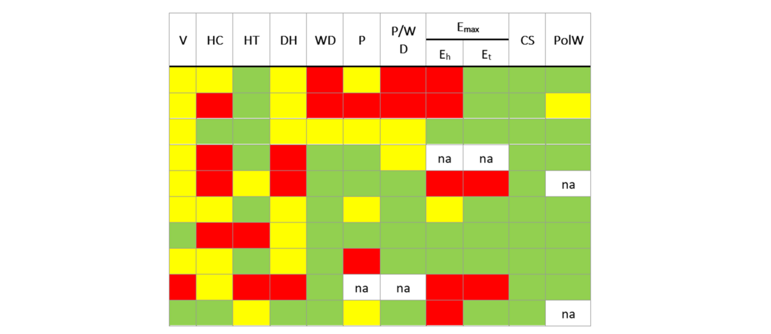
Figure 30 - Example of summary of condition assessment of composite insulators in Europe
Using the results of condition assessment, considering data from different tests and correlation of dynamics of some of the parameters, examples of practical recommendations are summarized in Table 6.
Source of data | Manufacturer | Years in service | Practical recommendations |
|---|---|---|---|
Europe | A-1 | 11 | These insulators performed rather well after removal from service (based on broad statistics for 4 designs) and no maintenance actions are required. Service data for up to 30 years were available, showing that some material ageing might be observed for older insulators, and that the electric field grading can be improved for several insulator designs. An audit of this manufacturer could be recommended. |
A-2 | 16 | ||
A-3 | 7 | ||
A-4 | 30 | ||
B-1 | 5 | These insulators perform very well, but this is confirmed for one design only, and after only 5 years in service. No maitenance actions are required. This manufacturer can be considered as promising. | |
C-1 | 35 | These insulators were tested on a limited scale, i.e., only two designs retrieved from service after up to 35 years. The insulators were in rather good condition, however, based on I²G experience these insulators might be of varying quality depending on the specific historical design and the pollution level of the site. No immediate maitenance actions are required. | |
C-2 | 10 | ||
D-1 | 6 | These insulators performed well, but this was indicated only by one design with only 6 years in service. No maitenance actions are required considering also broad positive statistics of testing 7 designs of new insulators manufactured at different factories (old and new). An audit of new factory might be recommended. | |
E-1 | 11 | These insulators were investigated in this project on a limited scale, i.e., only one design which was retrieved from service. The insulator was in rather poor condition, due to non-optimal material of housing and absense of grading rings. This insulator has an intrinsically lower ability of keeping the hydrophobicity properties, especially as it is strongly overstressed electrically as shown by the electric field calculations. It is recommended to remove these insulators. | |
F-1 | 4 | Only one insulator from service was available, however without any remarks. No maitenance actions are required. Based on I²G experience these insulators might be of varying quality depending on the specific historical design. An audit is recommended to check the present quality of manufacturing. | |
Australia | C-3 | 16 | The recommendation for these insulators, which have been in operation for 15+ years, is to replace all of them due to electrical issues with a core and serious deterioration of the housing. |
C-4 | 17 | ||
G-1 | 16 | It is recommended to monitor surface degradation of insulators at two specific OHLs, by removal and inspection of insulators from time to time. It is also recommended to inspect the sealing and housing in vicinity to the end fitting to make sure that the integrity of the sealing is intact. | |
G-2 | 14-21 | ||
H-1 | 3 | It is recommended to remove more insulators of this type and evaluate their adhesion core/housing in nearest years (starting with the next year). If low adhesion core/housing will be consistent, it would be advisable to replace these insulators within 3-5 years. This period may be corrected based on the results of additional after-service adhesion tests of these insulators. | |
I-1 | 1 | It is recommended to replace these insulators within 3-5 years. This period may be corrected based on the results of additional after-service hydrophobicity and adhesion tests of these insulators. It is recommended to start with replacement in the areas with higher level of precipitation (both humidity and rain), because the probability to get moisture in the interface is higher for such areas. | |
South Africa | A-5 | 40 | These insulators are at high risk due to sealing and adhesion issues and replacement is required. |
A-6 | 26 | ||
A-7 | 15 | ||
C-3 | 15 | These insulators have not reached end of life. They do not need immediate replacement. Every five years, one aged in-situ insulator should be removed from the specific OHL to determine its current condition. | |
J-1 | 30 | These insulators have not reached end of life. They do not need immediate replacement. Every five years, one aged in-situ insulator should be removed from the specific OHL to determine its current condition. |
5.2. Preliminary proposal for optimal after-service test matrix
Analysis of the results from three different programs for the after-service tests were used to make a proposal for an optimal matrix for such tests. This matrix should provide reliable data for the condition assessment, and, at the same time, should be cost-effective. Such a matrix is considered a key issue for the optimized maintenance of composite insulators based on the so-called “inspection-based maintenance”. The intention is to acquire a limited number of insulators along with electrical and environmental data.
The preliminary optimized minimum test program for insulators removed from service is as follows:
- Visual inspection along with UV- and IR-inspection results are useful to choose the insulators for inspections.
- Measurement of standard pollution parameters (ESDD/NSDD according to IEC 60815-1), note that this does not provide the site pollution severity level.
- Assessment of hydrophobicity class according to IEC TS 62073.
- Measurement of hardness of housing according to IEC 62217.
- Measurement of dynamic hydrophobicity according to this paper.
- Adhesion test of fiberglass rod/housing including water diffusion and pull-off tests according to this paper (considering guard electrode application for some of the insulators).
- Dye penetration test on core according to IEC 62217.
- Inspection of cross-section of sealings.
- Corrosion and saltwater boiling test of fitting/sealing proposed in [18].
6. Conclusion
This paper summarizes the after-service investigations of 84 individual line composite insulators made by ten different manufacturers from Europe, Asia, and USA. These insulators were installed in light polluted environments with a time in service of up to 40 years. The majority of silicone rubber-based insulators were in rather good condition from both pollution and ageing point of view, which strongly supports their future use. This is valid for properly manufactured, dimensioned, and electrically graded insulators. Similar results are expected for medium-heavy environments, while for very heavy and extreme polluted environments similar investigation should be performed.
The creation of an optimal minimum matrix for the after-service tests is considered as a key issue for the optimized maintenance of composite insulators based on the so-called “inspection-based maintenance”. Such matrix is proposed in this paper. Similar matrix can be applied for more severe polluted areas with some additional tests, e.g., clean fog test to evaluate actual pollution performance.
References
- I. Gutman, A. Deckwerth, K. Halsan, M. Leonhardsberger, P. Meyer, L. Diaz, M. Radosavljevic, P. Trenz, K. Varli, K. Välimaa: “Application of Composite Insulators: Perceptions vs. Service Experience”, 2022 INMR World Congress, Berlin, Germany, 16-19 October 2022
- CIGRE WG B2.21: “Guide for the Assessment of Composite Insulators in the Laboratory after their Removal from Service”, CIGRE TB 481, December 2011
- IEC/TS 60815-1, “Selection and dimensioning of high-voltage insulators for polluted conditions - Part 1: Definitions, information and general principles”, Edition 1.0, 2008-10
- IEC/TS 60815-3, “Selection and dimensioning of high-voltage insulators for polluted conditions - Part 3: Polymer insulators for a.c. systems”, Edition 1.0, 2008-10
- CIGRE WG D1.44: “Pollution test of naturally and artificially contaminated insulators”, CIGRE TB 691, July 2017
- STRI Guide: "Guide for Visual Identification of Deterioration & Damages on Suspension Composite Insulators", STRI Guide 5, 2005
- EPRI field guide: "Visual inspections of polymer insulators", ID 3002005627, 2015
- W. L. Vosloo, R. E. Macey and C. de Tourreil: “The practical guide to outdoor high voltage insulators”, Eskom Power Series, July 2004
- CIGRE WG 22.03: “Composite insulator handling guide”, CIGRE TB 184, April 2001
- IEC TS 62073: "Guidance on the measurement of hydrophobicity of insulator surfaces", Ed. 2.0, 2016-02
- A. Dernfalk, P. Sidenvall, I. Gutman: "Development of the test capable to reveal level of adhesion between fibreglass rod and housing of composite insulators", CIGRE-IEC 2019 Conference on EHV and UHV (AC & DC), April 23-26, 2019, Hakodate, Hokkaido, Japan, paper P1-10
- I. Gutman, A. Dernfalk, J. Lundengård, P. Sidenvall, A. Deckwerth, L. Diaz, K. Halsan, M. Leonhardsberger, M. Radosavljevic, P. Trenz, K. Varli, K. Välimaa: “Test methods and criteria for validation of functional properties of composite insulators related to materials and interfaces”, CIGRE 2022, D1-10828_2022
- CIGRE WG B2.69: “Coating for improvement of electrical performance outdoor insulators under pollution conditions”, CIGRE TB 837, June 2021
- CIGRE WG C4.303: “Artificial pollution test for polymer insulators”, CIGRE TB 555, October 2013
- ISO 868: “Plastics and ebonite – Determination of indentation by means of a durometer (Shore hardness)”, second edition, 2003
- IEC 62217: “Polymeric HV insulators for indoor and outdoor use – General definitions, test methods and acceptance criteria”, Ed. 2.0, 2012-09
- I. Gutman, C. Ahlrot, P. Aparicio, A. Berlin, T. Condon, A. Dernfalk, J.-F. Goffinet, K. Halsan, K. Kleinekorte, J. Lundengård, M. Radosavljevic, P. Sidenvall, S. Steevens, K. Varli, K. Välimaa: “Development of Innovative Test Procedure for Evaluation of Adhesion of Core-Housing of Composite Insulators: from Root Cause of Failures in Service to Reproducible Test Procedure”, CIGRE Science & Engineering, N. 20, February 2021, p.p. 171-182
- K. Varli, S. Steevens, J. Unterfinger, A. Dernfalk, I. Gutman, J. Lundengård, P. Sidenvall: “Benchmarking of sealing systems of composite insulators: ideas for innovative test methods”, CIGRE Science & Engineering, N. 25, June 2022, p.p. 108-131
- IEC 60383-1: “Insulators for overhead lines with a nominal voltage above 1000 V, Part 1: Ceramic or glass insulator units for a.c. systems – Definitions, test methods and acceptance criteria”, Fourth edition, 1993-04
- Australia/New Zealand Standard AS/NZS 4680: "Hot-dip galvanized (zinc) coatings on fabricated ferrous articles", 2016
- P. Sidenvall, I. Gutman, A. Deckwerth, L. Diaz, P. Meyer, J.F. Goffinet, K. Halsan, M. Leonhardsberger, M. Radosavljevic, P. Trenz, K. Varli, K. Välimaa: “Limits of electrical field for composite insulators: state-of-the art and recent investigations of insulators purchased by power utilities”, CIGRE Science & Engineering, N. 24, February 2022, p.p. 1-14
- Comsol Multiphysics® 5.6, 2020, www.comsol.com.
- A.J. Philips, A.J. Maxwell, C.S. Engelbrecht, I. Gutman: “Electric Field Limits for the Design of Grading Rings for Composite Line Insulators”, IEEE Transactions on Power Delivery, Vol. 30, No. 3, June 2015, p.p. 1110-1118
- IEC 61109: “Insulators for overhead lines – Composite suspension and tension insulators for a.c. systems with nominal voltage greater than 1000 V – Definitions, test methods and acceptance criteria”, Edition 2.0, 2008-05
- I. Yu. Gutman, E. A. Solomonik, V. N. Solomatov, Yu. N. Yashin: "Operation and Field Tests of Overhead Line Composite Insulators with Silicone Rubber Cover", 8th International Symposium on High Voltage Engineering, Yokohama, Japan, 23-27 August 1993, 47.13