Effect of temperature on overhead aluminium and aluminium alloy conductor creep
Authors
A. OMRANI, S. LANGLOIS, M. DEMERS, L. BINETTE
Université de Sherbrooke - Canada

Summary
For overhead line conductors, the permanent deformation as a function of time, known as creep, strongly depends not only on the mechanical tensile stress but also on the temperature. This paper presents the results of creep tests on individual aluminium 1350-H19 and aluminium alloy 6201-T81 wires under different stress levels at high temperatures. The effect of temperature on the creep behaviour of the tested wires is also compared to results of creep tests carried out on conductors constituted by the same two materials. An experimental creep factor, relative to the creep rate at a reference temperature of 20°C, was also calculated for all tests and compared with available equations in literature. Creep factors (CF) were found to range from 1.5 at 38°C to 3 at 70°C for the aluminium wires and from 1 at 38°C to 2 at 70°C for the aluminium alloy wires.
Keywords
Creep - Creep factor - Overhead conductors - wires specimen - Temperature1. Introduction
Creep of overhead conductors starts at the installation phase when the conductor is being submitted to the tension load and continues at a decreasing rate as long as the applied load persists [1]. This deformation results in an elongation of the conductor and an increase in its sag. The creep rate considered when designing overhead conductors typically corresponds to a reference temperature of 20 ºC. However, during their service life, the real temperature of some overhead conductors, regularly operated at high current levels, reaches values significantly higher than the reference temperature, thus affecting the creep rate. It is indeed well-known that the creep rate increases with temperature for metallic materials [2]. Consequently, line clearances may be lower than expected which may compromise the ability to maintain a minimum safe distance above the ground. The effect of temperature on creep rates should then be taken into consideration when designing overhead conductors to avoid such problems [3].
In the context of overhead conductors, creep can be studied through experimental tests on laboratory span conductors according to IEC 61395 standard [4] as well as through experimental tests on individual wires forming the conductor as suggested by [5]. The full conductor testing approach has often been adopted and equations have been developed to predict creep of conductors. The creep tests performed by [1] on the Aluminium Conductor Steel Reinforced (ACSR) Arbutus showed that the applied load when combined with a high temperature induces an important increase in the creep strain of the bimetallic conductor. Temperature effect is more important on the All Aluminium Conductor’s (AAC) creep than on the ACSR conductors’ creep as mentioned by [5]. However, such data on the effect of high temperatures on overhead conductors’ creep are scarce. The wire approach, which consists of performing creep tests on individual wires, can be an alternative low-cost method to predict the effect of high temperatures on the creep behaviour of overhead conductors. However, it needs to be compared and verified with conductor tests because wire tests do not allow to include some deformations due to the geometric settlement of conductors [5].
This paper proposes the study of the creep behaviour of aluminium and aluminium alloy wires under high temperatures through carrying out experimental tests on individual wires. A wire creep test bench was developed following the recommendations of the IEC 61395 standard [4]. The creep of overhead conductors is in this study evaluated through the creep of individual wires which constitute them. In this perspective, creep tests were also performed on AAC and All Aluminium Alloy Conductor (AAAC) conductors and the obtained results constituted validation data.
2. Experimental protocol
2.1. Wire creep experimental test setup
2.1.1. Experimental test setup configuration
The wire creep test bench was designed to test four wires at the same time (Fig.1). It is mainly composed of a thermally insulated chamber having a height of 2.16 m, a length of 1.26 m and a width of 1.22 m. The walls, the roof, the floor and the door of this chamber are constituted from outside to inside of a plywood panel, an expanded polystyrene isolation layer, a second plywood panel and a gyprock panel. This design allows maintaining the heat in the thermal chamber during the test while avoiding the risk of fire.
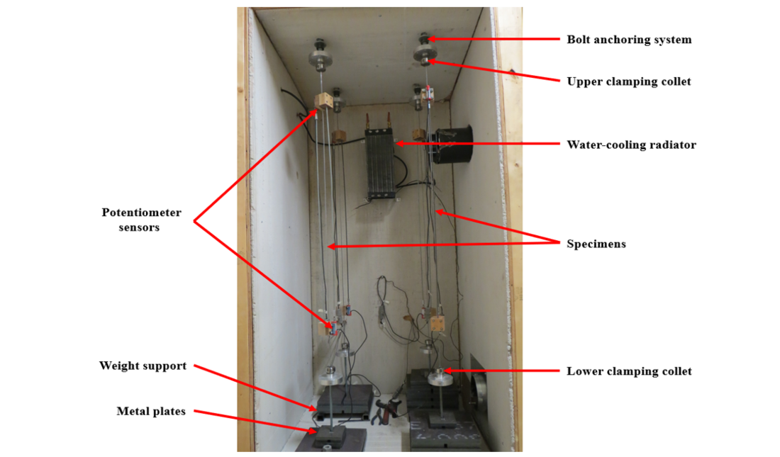
Figure 1 - Overview of the wire creep experimental test setup
Inside this chamber, each tested wire was vertically fixed through the chamber roof by means of a clamping collet attached to a threaded rod anchoring system as shown in Fig.2. The thread rods extend over the roof of the chamber to pull on the wire and thus applying the load. The second extremity of each wire was fixed to a clamping collet which is attached to a weight support initially resting on the floor. The mechanical loading is applied by placing metal plates on the weight support and lifting the whole assembly by screwing the nut related to the threaded rod anchoring system. All components used for the mechanical load application such as the lower clamping collet, the weight support and the metal plates, are individually weighted on a scale with 1.0 g precision. Final adjustment of the load is made by adding weighted bolts or nuts.

Figure 2 - Threaded rod anchoring system for the wire creep tests
The required high temperature was provided by a heater placed outside the insulated chamber and connected to it through an insulated pipe for recirculation of the air (Fig.3). For the 20°C reference temperature, which is lower than the laboratory temperature, cooling was done using a water-cooling radiator placed inside the insulated chamber (Fig.1). The uniformity of the temperature in the chamber is maintained by three fans running continuously; two are behind the cooling radiator and the third force a flow in the pipe of the heater. The electronic controller monitors the temperature in the chamber via a thermocouple probe and controls the heater only. The controller has an output connected to the data acquisition system to record the temperature.
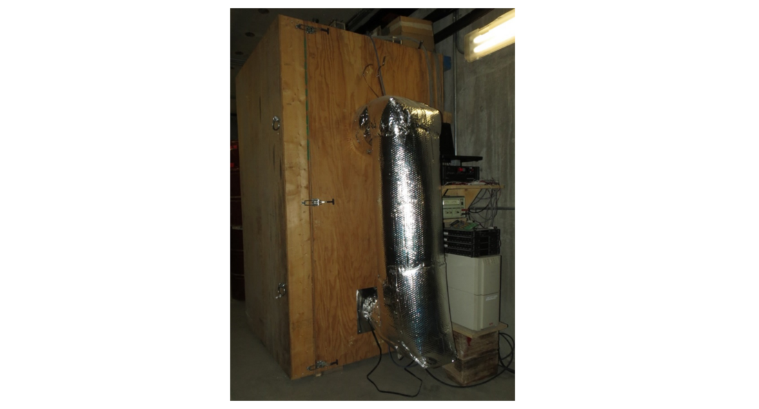
Figure 3 - Heating system for the wire creep test setup
A pair of displacement sensors is installed on opposite sides of each tested wires. These sensors are linear potentiometers with a range of 10 mm and a precision of 0.005 mm. The pair of potentiometers shares common attachments at a distance of 140±10 mm from the clamping collets to avoid boundary effects. The gauge length is extended with 915 mm long threaded bar connecting a potentiometer to the other attachment. The gauge length, measured from centre to centre of the attachments of the potentiometers, ranged from 981 mm to 997 mm. This length is measured before starting each test and used to calculate creep. These sensors, allowing the measurement of the creep, are connected to a data acquisition system which ensures the reading and recording of the data throughout the test. An uninterruptible power supply unit is installed to ensure the continuity of the data acquisition in case of a short power shutdown.
2.1.2. Experimental procedure
The procedure for creep tests on wires can be divided in five steps. The first step of the experimental procedure is to select and place the metal plates on the weight support, such that the total supported weight corresponds to the stress to be applied. Positioning the weight support at the exact vertical position of the upper clamping collet is important to avoid the swing of the mass when lifted.
The second step starts by straightening the wires taken from the spool. During the manual straightening, attention was paid to avoid over-bending as much as possible in order to minimize residual strain. The straightened wires are then fixed between the upper and lower clamping collets while the whole weight assembly remains resting on the floor. Once the wires are installed, displacement sensors are fixed on each side of each specimen as shown in Fig.4 and their initial positions are adjusted. Pencil marks are drawn on the wires to detect whether there will be a sliding or not. The preparation of the wires is completed by measuring the initial gauge length and taking photographs. The photographs are taken for the initial state of the specimen before starting the test and they are used for visual inspection of the specimen at the end of the test.
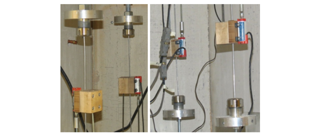
Figure 4 - Positioning of the potentiometer sensors in the wire creep tests
At the third step, the door of the insulated chamber is closed to start the thermal conditioning. The electronic controller is set to the required temperature, the acquisition system is activated and the internal fans are started. The heating system is left running several hours, usually overnight, with unloaded wires until temperature stabilization.
The fourth step consists to lift the complete wire/weight support assemblies from outside the chamber by screwing gradually the nuts located on top of the chamber. The nut is screwed until there is a gap of 10 to 20 mm between the weight support and the floor. For creep tests, loading procedure is a very important step which must be well controlled to ensure that the applied loads always remain below the specified test load for the specimens. Overload could induce permanent deformation leading to false results for creep. To avoid torsion stress during the loading process, the threaded rod is held against rotation.
The last step consists in recording elongation for a minimal duration of 1000 hours. The recorded signals are the displacements from eight potentiometers, the temperature from the controller and the excitation tension (voltage) from the power supply. The last value is useful since potentiometer signal is proportional to the excitation. The recording rate is one reading of all channels per second for the loading step and the first hour of creep. Then the recording rate is reduced to one reading per minute for the remaining of the test.
2.2. Conductor creep experimental test setup
2.2.1. Experimental test setup configuration
The conductor creep experimental test setup used in the present study was mounted vertically to a reaction wall of the structure laboratory at the University of Sherbrooke as shown in Fig.5. Its design follows similar methodology as that of the individual wires creep experimental test setup, which is a suspended mass for the load and a temperature-controlled environment. It is designed for two conductors under load up to 25 kN each. The temperature-controlled environment is provided by two insulated steel boxes joined by two vertical insulated steel tubes having an inner diameter of 200 mm. The thermal insulation is provided by a 150 mm thick glass wool layer between the steel skins of the boxes and around the tubes. The height of the installation is close to 12 m, the total length of the tested conductors is 9.6 m and its heated length is 8.2 m.
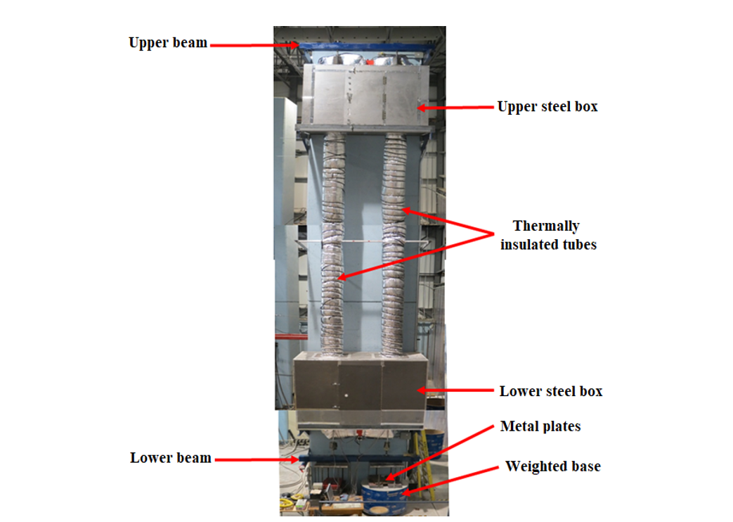
Figure 5 - Overview of the conductor creep experimental test setup
To minimize the conductor connexion length, a conical anchoring socket was designed (Fig.6.). The steel socket is composed of two bolted halves to be reusable, and threaded holes on the large end for connexion with other parts. To improve the adherence, the wires composing the conductor are fanned and 180° bended and then cleaned with spray degreaser. The preparation of the conductors is completed by filling the conical anchoring socket with an epoxy-based rope capping kit.
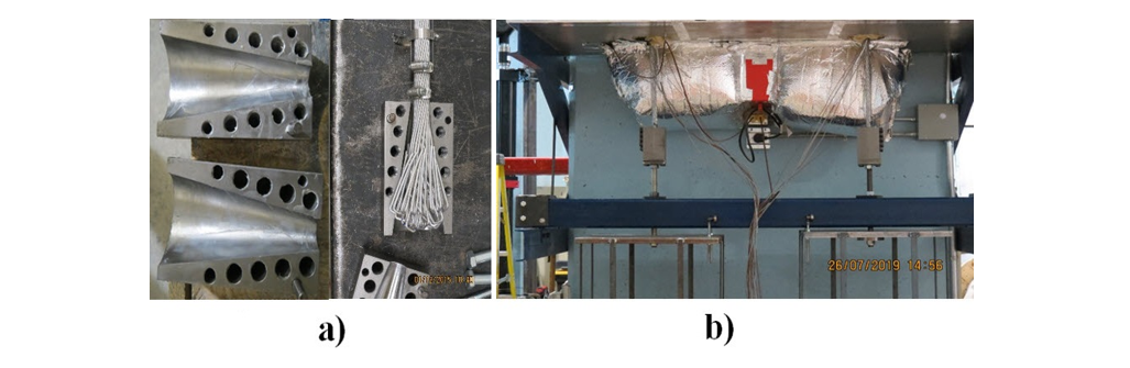
Figure 6 - (a) Conical anchoring system and (b) conductor’s lower connexion in the conductor creep test setup
The mechanical loading is applied through two weighted bases, which are connected to the lower end of each conductor and initially suspended on the lower beam. The bases are partially filled with concrete. Metal plates are placed above the concrete to adjust the weight such that to obtain the target stress value. The weight of each base with its concrete was measured with a 250 kN load cell while the weight of the added steel plates is measured by batch on a 500 kg scale. As for conductor in service where rotation is prevented by supporting elements, the rotation of the tested conductor is prevented with roller bearing attached to the bases and resting against the lower beam. Validation tests with conductors free in rotation showed that step elongation occurs due to delayed rotation, even more than 100 hours after loading.
To maintain uniform temperature on the testing length of the conductors, the steel boxes and tubes are designed to force a continuous air flow. Each steel box is divided in two compartments with an internal door. The heating and ventilation systems are installed on an external derivation from one compartment to the other of each steel box. This system forces the air to flow up in the right tube and down in the left tube. At the exit of the steel tube, the air flow was measured to be more than 2 m/sec. The uniformity of the temperature was assessed with 5 thermocouples installed on the first conductor; middle of lower box, top of lower box, middle of the tube, bottom of upper box, and middle of upper box. For the 20°C reference temperature, which is lower than the laboratory temperature, cooling was done using a domestic air conditioning unit installed in the access door of the upper steel box.
As for the wire creep tests, experimental measurements are carried out using potentiometer sensors attached to the tested conductor. A pair of displacement sensors is installed on opposite side of each tested conductors near the top of the lower steel box. These sensors are linear potentiometers with a range of 25 mm and a precision of 0.01 mm. Thin steel wires, attached to the potentiometer via a spring system to keep a small tension, are used to provide a long gauge length. An attachment for a pair of opposite thin steel wires is installed near the bottom of the upper steel box. The gauge length, measured before starting each test and used to calculate creep, is approximatively 6.33 m. The position of the upper and lower attachments provides at least 0.9 m of conductor inside the heated environment outside the gauge length and more than 1.2 m from the anchor sockets. The sensors allowing the measurement of the creep are connected to a data acquisition system which ensures the reading and recording of the data throughout the test. An uninterruptible power supply unit is installed to ensure the continuity of the data acquisition in case of a short power shutdown.
2.2.2. Experimental procedure
The procedure for creep test on conductors is also divided into the same five steps. The first step of the experimental procedure is to select and place the metal plates on the bases, such that the total supported weight corresponds to the stress to be applied. The correct position of the bases was determined at the installation of the upper and lower beams.
The second step starts by casting the anchoring sockets on both ends of the conductors and inserting them in the insulated steel tubes. There was no attempt to straighten the conductors because some bending is required during their manipulation. The lower anchoring socket is bolted to the base while the upper anchoring socket is bolted to the loading threaded bar. Once the conductors are installed, displacement sensors are fixed on each side of each specimen as shown in Fig.7 and their initial positions are adjusted with turnbuckles. Then, four thermocouples, one close to each attachment for displacement sensors, are installed on the conductors with electrician tape to monitor their temperature. Pencil marks are drawn on the conductors to detect whether there will be a sliding or not. The preparation of the conductors is completed by measuring the initial gauge length along with other dimensions and taking photographs.
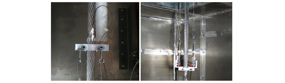
Figure 7 - Potentiometers attachment configuration in the conductor creep test setup
At the third step, the internal door and the access door of both insulated steel boxes are closed. The circular openings for passage of the conductors in the steel boxes are closed with a metal sheet and then packed with insulation wool. The ventilation system is started first before activating the acquisition system and beginning the thermal conditioning by setting the electronic controller to the required temperature. When required, the adjustable resistor connected to the upper heater is set to achieve equal temperature on both tested conductors. The heating system is left running several hours, usually overnight, with unloaded conductors until temperature stabilization.
The fourth step consists in lifting the complete conductor/base assemblies. To apply the load, a hydraulic hollow jack is used on top of the upper beam to pull the threaded rod attached to the upper anchoring socket of the conductor until the base is lifted from the lower beam. At this point, the lower nut is unscrewed to allow creep elongation of the conductor, and the upper nut is screwed to contact the upper beam before removing the jack.
The last step consists in recording elongation for a minimal duration of 1000 hours. The recorded signals are the displacements from four potentiometers, the temperature from the controller, the temperature from the four thermocouples on the conductors and the excitation tension (voltage) from the power supply. The recording rate is one reading of all channels per second for the loading step and the first hour of creep. Then the recording rate is reduced to one reading per 100 seconds for the remaining of the test. Also, the space between the lower beam and the nut is checked regularly and unscrewed when required to avoid contact that would lead to reduction of the load.
3. Tests parameters
Creep tests were carried out on 1350-H19 aluminum and 6201-T81 aluminum alloy wires with an active length of around 1 m and diameters of 4.33 mm and 2.80 mm respectively (Table I). These two materials were submitted to different levels of mechanical stress. All mechanical loadings were tested for the four following temperatures: 20°C, 38°C, 55°C and 70°C.
| Material | Aluminum 1350-H19 | Aluminum alloy 6201-T81 |
|---|---|---|
Diameter (mm) | 4.33 | 2.80 |
Length (m) | 0.99 | |
Elastic modulus (MPa) | 68900 | 69000 |
Rated Tensile Strength (kN) | 2.553 | 2.03 |
Failure elongation (%) | 1.7 | 6 |
Table 2 presents the details of these tests as well as those of the creep tests performed on conductors constituted of strands of the same production lot. For this last test type, two conductors with an active length of 6.33 m were tested. The first one is the AAC Dahlia conductor composed of nineteen (19) 1350-H19 aluminium wires with a diameter of 4.33 mm, and the second one is the AAAC Aster-228 conductor constituted of thirty-seven (37) 6201-T81 aluminium alloy wires with a diameter of 2.80 mm (Table III). These conductors were tested under different mechanical stress levels and for the same temperatures as those of the wire’s tests. All creep tests were carried out for 1000 hours as recommended by the IEC 61395 standard [4].
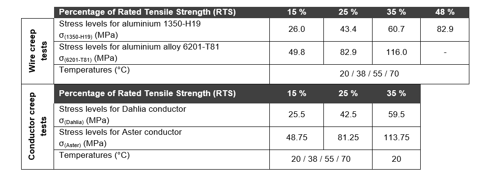
Table 2 - Creep tests configuration
| Conductor type | AAC Dahlia | AAAC Aster-228 |
|---|---|---|
Metallurgical composition | 1350-H19 | 6201-T81 |
Number of wires | 19 | 37 |
Wires diameter (mm) | 4.33 | 2.80 |
Length of the specimen (m) | 6.33 | |
Rated Tensile Strength (kN) | 47.6 | 74 |
4. Results and discussion
4.1. Stress effect
To study the effect of the mechanical loading on the creep behaviour of the tested materials, the experimental results of the wire creep tests are presented and compared to those of the corresponding conductor creep tests in Fig.8 and Fig.9, respectively for the aluminium and the aluminium alloy wires, as a function of the stress level. For all tests, the shape of the obtained curves follows an exponential law as a function of time. For both materials and at a constant temperature, results show that the creep always increases when increasing the mechanical loading. This observation is valid for both Dahlia and Aster conductors as well as for both wire specimens. At a stress level of 48% RTS, the creep reaches around five times the values obtained at a stress level of 15% RTS for the aluminium wires while for the aluminium alloy wires the increasing creep factor is around three times as the stress level increases from 15% RTS to 35% RTS. These results confirm that the mechanical loading has an important effect on the creep behaviour of the wires regardless of the type of material.
Results comparison between conductors and wires of the same material shows that after 1000 hours of test duration, the conductor creep is generally greater to the one of the corresponding wire. In fact, the wires tightening during the stranding process of conductors is not perfect which always results in a geometrical settlement between wires when the conductor is stretched [5]. This geometrical settlement as well as the local deformations at the contact points between the conductor’s wires, induce an additional elongation which is not induced in the case of single wires.
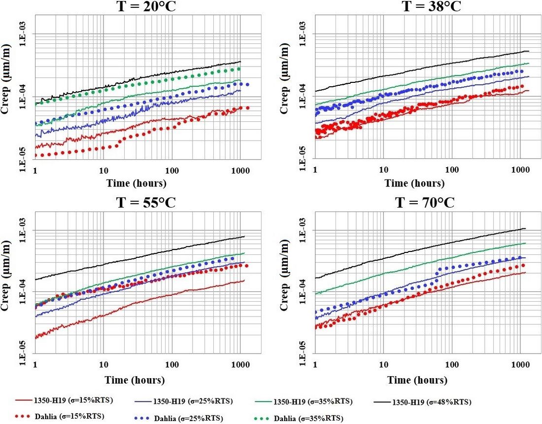
Figure 8 - Comparison of the creep curves of the aluminium 1350-H19 wires and the Dahlia
conductor as a function of the stress level
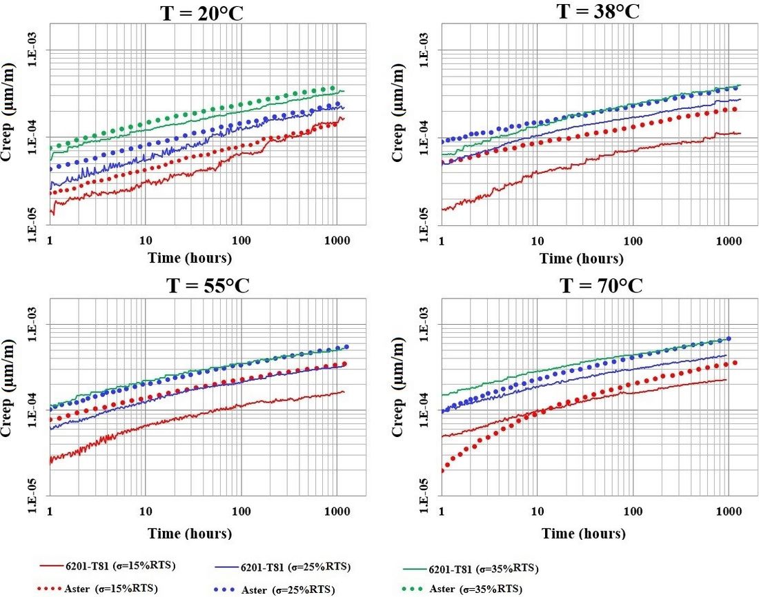
Figure 9 - Comparison of the creep curves of the aluminium alloy 6201-T81 wires and the Aster
conductor as a function of the stress level
4.2. Temperature effect
As for the mechanical loading, the comparison of the wire and conductor creep tests results as a function of the temperature shows that the creep behaviour of both aluminium and aluminium alloy materials is affected by this parameter. As shown in Fig.10 and Fig.11, respectively for the aluminium and aluminium alloy wires, increasing the temperature at a constant stress level always leads to an increase in the creep for both materials. After 1000 hours of test duration, the creep at a temperature of 70 ºC reaches around three times the one corresponding to 20 ºC for the aluminium wires. For the aluminium alloy wires, the increasing factor is around two times for the same temperature range.
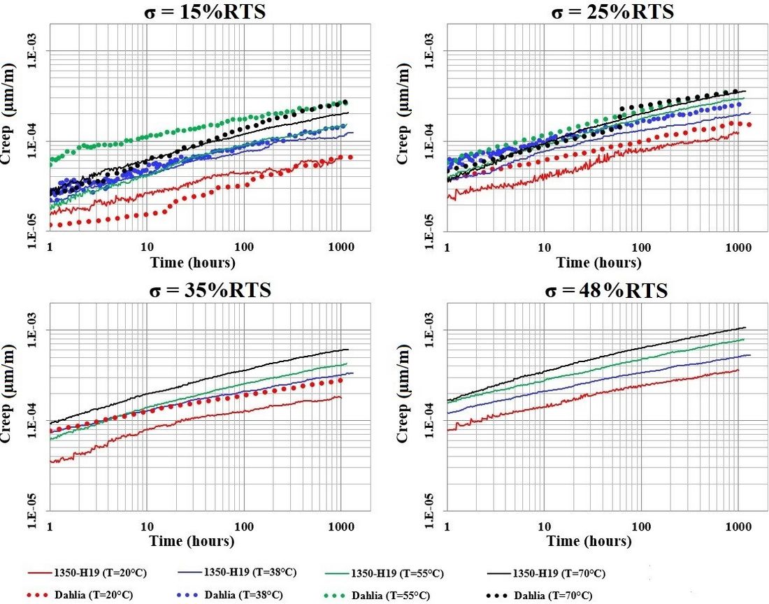
Figure 10 - Comparison of the creep curves of the aluminium 1350-H19 wires and the Dahlia conductor as a function of the temperature
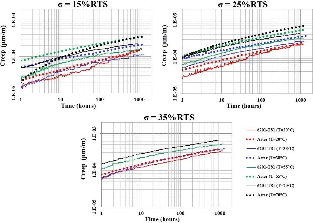
Figure 11 - Comparison of the creep curves of the aluminium alloy 6201-T81 wires and the Aster
conductor as a function of the temperature
The temperature effect becomes more important when combined with an increase in the mechanical loading as shown in Table 4. In fact, an increase of more than nine times for the creep of the aluminium wires is noticed when comparing the results at a mechanical loading of 15% RTS and a temperature of 20ºC to those corresponding to 35% RTS and 70ºC. This increasing factor was less important for the aluminium alloy wires and it was equal to around five times.
|
| Loading parameters | Increasing factor | |
|
| 15% RTS and 20 ºC | 35% RTS and 70 ºC | |
Creep strain | Aluminium 1350-H19 | 6.38 * 10-5 | 59.84 * 10-5 | 9.38 |
Aluminium alloy 6201-T81 | 14.67 * 10-5 | 66.83 * 10-5 | 4.55 | |
4.3. Creep factor
The creep factor, defined as the ratio between the creep at a given temperature T and the one at the reference temperature of 20ºC, is a parameter that allows quantifying the effect of temperature on the creep. Different empirical equations were developed to express this factor as a function of temperature. Nigol and Barrett [6] found that the creep factor can be expressed as an exponential function of temperature as shown in (1). Harvey and Larson [7] proposed a different equation to express this factor as a function of temperature (2). For aluminium based materials, these equations are valid for temperature greater than 20ºC.
(1)
(2)
Fig.12 and Fig.13 present the variation of the creep factor, respectively for the aluminium and aluminium alloy specimens (wires and conductors), as a function of the stress level at 38ºC, 55ºC and 70ºC. The increase of the experimental creep factor with increasing temperature can be observed on these figures. Generally, creep factors are less than 2.0 at 38ºC and over 2.0 at 70ºC. Also, creep factors for aluminium wires (Fig.12) are always larger than those for aluminium alloy wires (Fig.13). The comparison of the experimental results with the ones obtained through the previous equations shows that Nigol and Barrett equation fits with the experimental results at low temperatures but both equations overestimate this parameter for high temperatures.
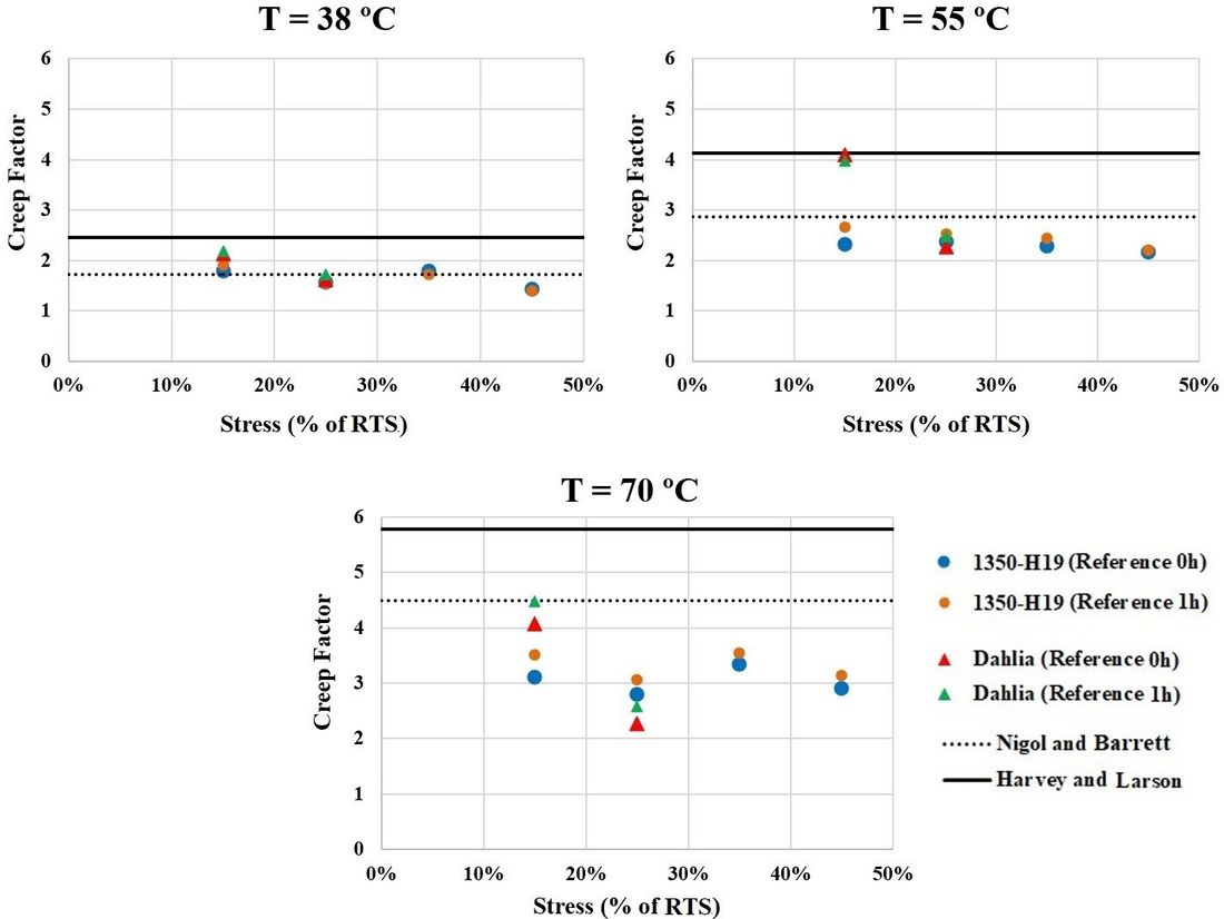
Figure 12 - Comparison of the experimental creep factors with the theoretical equations for the aluminium 1350-H19 wires and the Dahlia conductor
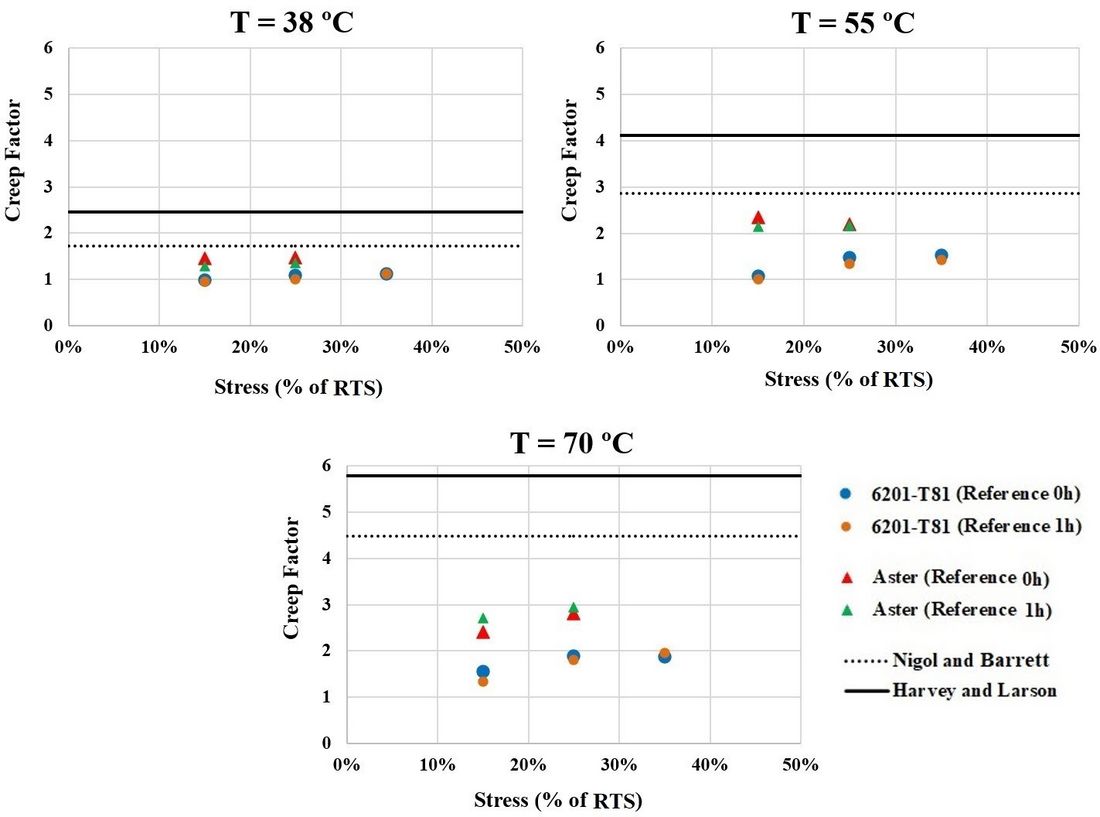
Figure 13 - Comparison of the experimental creep factors with the theoretical equations for the
aluminium alloy 6201-T81 wires and the Aster conductor
The experimental creep factors shown in these figures were first calculated considering the creep measured after 1000 hours from the beginning of the test which corresponds to the application of the last loading step (considering 0 hour as reference time). To assess the effect of the first test hour on the creep results, the creep factors were also calculated considering the resulting creep obtained from the difference between the values measured at 1000 hours and at 1 hour (considering 1 hour as reference time). The one hour point is more consistent with current practice that considers the first hour of creep in the stress-strain curve of conductors. The zero hour point has the conceptual advantage of considering the complete creep process.
Observing the results relative to both time references, it appears that the creep at the first hour of the test does not have an overall impact on the creep factor whether for wires or conductor specimens. Experimental results show also that the creep factor is almost constant as a function of the stress level for the aluminium as well as the aluminium alloy wires.
However, for the conductors, the creep factor seems to be decreasing with respect to the stress level for the Dahlia conductor while it appears insensitive in the case of the Aster conductor. In addition, the obtained conductors creep factors are generally greater compared to the ones of the wire specimens constituted of the same material. Also, in general, the creep factors obtained with conductors seem to have more dispersion than for wires at different temperature and stress levels. This might be due in part to the geometrical settlement between conductor wires and the local deformation at the contact points between them which is not induced in the case of single wires.
At this stage, it is premature to conclude about the trend of the creep factor for the tested conductors since the presented results are only for two stress levels. This should be further investigated through carrying out more tests on conductors, including tests at least at a third stress level as it was done for wires.
5. Conclusion
Creep tests were carried out under different stress levels at high temperatures on aluminium and aluminium alloy wires as well as on conductors constituted by the same materials. Analysis of the results leads to the following conclusions:
- Creep of the tested specimens increases with respect to temperature, the effect of which becomes more important when combined with an increase in the mechanical loading;
- Conductor creep is always greater than that of the individual wires which is due to the local deformations at the contact points and to the geometrical settlement between the conductor’s wires when the conductor is stretched;
- Creep factor is almost constant as a function of the stress level and is affected by the temperature. However, creep factors seem to be different for aluminium and aluminium alloy materials.
- For conductors, creep factor is generally greater compared to the one of the wire specimens constituted of the same material. The available experimental results remain insufficient to make a conclusion about the trend of the creep factor for the tested conductors.
- These test results show the importance of considering the effect of temperature on creep for AAC and AAAC conductors. They provide valuable data to account for this effect on conductor creep.
Acknowledgement
The authors would like to acknowledge the financial support of Hydro-Québec, RTE, NSERC and InnovÉÉ. They also thank Hydro-Québec, RTE and General Cable for providing the conductors and wires specimens.
References
- J.R. Harvey, "Creep of transmission line Conductors", Power Apparatus and Systems, IEEE Transactions, vol.88, No.4, pp. 281-286, 1969.
- F. Saint-Antonin, "Essais de fluage", Technique de l’ingénieur, Essais mécaniques sur les métaux et alliages, p. 14, 2013.
- F. Jakl and A. Jakl, "Effect of elevated temperatures on mechanical properties of overhead conductors under steady state and short-circuit conditions", IEEE Transaction on Power Delivery, vol. 15, No. 1, pp. 242-246, 2000.
- Overhead electrical conductors – Creep test procedures for stranded conductors, IEC 61395 Standards, pp. 4-18, 1998.
- M.M. Cojan, R. Helms, Nakayama, M.P. Nicolini, M.G. Orawski, M.E. Reina, M.W. Schroeder, M.J. Bradbury, M.P. Paoli and M.P. Ralston, "Permanent elongation of conductors: Predictor equation and evaluation methods", ELECTRA, CIGRE Journal, No.75, pp. 1-36, 1981.
- O. Nigol and J.S. Barrett, "Development of an accurate model of ACSR conductors for calculating sags at high temperature – PART 1", Technical report, Canadian Electrical Association, Ontario Hydro, Toronto-Ontario, 1980.
- J.R. Harvey and R.E. Larson, "Use of elevated-temperature creep data in sag-tension calculations", Power Apparatus and Systems, IEEE Transactions vol.89, No.3, pp. 380-386, 1970.