Simulation of a Grid with 100% Inverter-Based Generation and Synchronous Condensers for Grid Reference
Authors
J.R. RAMAMURTHY, A. JALALI, N. MODI - Australian Energy Market Operator (AEMO), Australia
F. SPESCHA - Total Eren Australia Pty Ltd, Australia

Summary
As the uptake of transmission- and distribution-connected inverter-based resources (IBR) continues to increase in scale and volume in the Australian National Electricity Market (NEM) power system, it is important to comprehensively investigate and prepare for the operation of a grid where all instantaneous energy demand can be met by generation from IBR. This paper presents an investigation into the above scenario, via Electromagnetic Transient (EMT) modelling and simulations. In particular, this investigation examines whether synchronous generators are needed to provide a synchronous grid reference for operation of IBR, where a majority of IBR installations still use grid-following technology.
While the operation of alternating current (AC) driven power systems without synchronous generators has been demonstrated in microgrids and other stand-alone applications with grid-forming converter installations, there remains an open-ended question on whether this is feasible in larger grids. The investigation presented in this paper is to assess the plausibility of maintaining a synchronous grid reference in a gigawatt (GW)-scale power system with zero synchronous generation online. It must be noted that in large grids of this size, synchronous generators may still be required for managing other power system needs such as resource adequacy, large ramping events, primary and secondary frequency control, and protection adequacy. However, this paper demonstrates that an adequately sized and properly sited synchronous condenser along with grid-connected IBR is capable of sustaining a synchronous grid reference, even when no synchronous generators or grid-forming converters are available in the system.
A number of scenarios were tested for a GW-scale power system using detailed EMT models of the IBR in a large-scale power system simulation to test the notion of synchronous condensers’ ability to sustain a synchronous grid reference, and to keep the grid-following IBR (including battery energy storage system (BESS)) latched-on and the power system stable following a disturbance.
Keywords
inverter-based resources (IBR) - synchronous condenser - grid-following - grid-forming converter - battery (BESS) - solar - wind - AC interconnector - synchronous grid reference and synchronous generator1. Introduction
The uptake of renewable energy generation in Australia has highlighted increasing difficulties in trying to dispatch fossil fuel-based synchronous generating units, owing to rising fuel costs coupled with accelerated retirements and ageing assets which require frequent maintenance [1],[2]. At times when market prices are insufficient for many synchronous generators to be commercially available, the market operator must rely on out-of-merit directions to dispatch them to support system security, which overall leads to inefficient outcomes for the power system [3]. As the Australian National Electricity Market (NEM) power system transitions to successfully integrate large amounts of wind, solar and battery energy storage system (BESS) inverter-based resources (IBR) in scale and volume, it is anticipated that some of these power system risks associated with resource adequacy will be eventually alleviated. However, during this transition period, it has become necessary to understand whether it is feasible to operate a grid where 100% of instantaneous demand is met by IBR with zero synchronous generators online, given that a large amount of IBR connected (including BESS) still use grid-following technology. An IBR based on grid-following technology relies on the phase-locked loop (PLL) mechanism for tracking the synchronous grid voltage, in the absence of which the PLL malfunctions and results in tripping of the IBR [4]. Hence, stable and balanced three-phase instantaneous voltage waveforms need to be provided at the terminals of grid-following IBR. The need for a balanced rotating synchronous grid voltage phasor (defined as grid reference) for the grid-following IBR to stay connected and latched-on in the absence of synchronous generators and/or grid-forming converters is the focus of this paper. This paper further highlights the role of synchronous condensers in sustaining this reference.
While the concept of operating an alternating current (AC) power system without synchronous generators is not novel, there are only a handful of simulation studies [4]-[6] that have reported this possibility in large gigawatt(GW)-scale power systems, and only a few stand-alone installations [7]-[11] that have implemented this, such as microgrids and grid-forming converter installations. Projects in [8]-[11] are described below. It should be noted that this is not a comprehensive listing and there may be other projects using back-to-back high voltage direct current (HVDC) installations or BESS that are black-start capable which are not included below.
1.1. SMA project, St Eustatius Island
SMA has demonstrated a 100% renewable grid with 4.15 megawatts (MW) of solar generation installed along with 5.9 megawatt-hours (MWh) of BESS capacity up to 2 MW overload (connected via grid-forming converters), capable of supplying the utility load and maintaining grid frequency with diesel-off mode [8]. This system has been proven to withstand normal day-to-day operations including fast moving cloud cover and load variations. SMA has also demonstrated similar projects with 100% renewable penetration, in the island of Saba and the town of Bordesholm, Germany.
1.2. Siemens Gamesa La Plana hybrid project, Spain
Siemens Gamesa owns a test plant with 850 kilowatts (kW) wind turbine generators, 245 kW solar photovoltaics (PV), 3 x 222 kW diesel generators and 0.5 MW/0.5 MWh BESS with grid-forming capability and 1.1 MW/0.75 megavolt amperes reactive (MVAr) load bank [9]. This system has been demonstrated to operate in zero diesel generation mode, including blackstart capability.
1.3. Micanopy Microgrid, Florida, United States of America (USA)
Duke Energy Florida, a major generation and utility company in the USA, operates an 8.25 MW/11.7 MWh BESS to support the town of Micanopy and nearby neighbours during grid outages, including a section of a distribution feeder [10]. The primary application is for islanding and frequency regulation. Duke Energy also operates other similar microgrid standalone projects, with BESS used to firm renewable generators and serve load as stand-alone power systems in events such as hurricanes. When not needed, the excess energy from the BESS is also exported to the grid.
1.4. National Renewable Energy Laboratory (NREL) campus, Colorado, USA
The NREL campus houses a multi‑energy test facility, including wind, PV generation and BESS operated in grid-forming mode, and a 7 megavolt amperes (MVA) power controller acting as a controllable grid interface [11]. This 13.2 kV microgrid is connected to the transmission grid via a 13.2 kV/115 kV step-up substation, which can run either connected to the main grid or islanded to support microgrid operation, with 100% renewables.
The portion of the Australian NEM mainland power system that was used for investigation in this paper is shown in Figure 1. The analysis has been carried out using a detailed time-domain electromagnetic transient (EMT)-based large-scale model of the system. A number of disturbances were considered to notionally assess the relationship between grid reference and synchronous condensers. The studied scenarios include disconnection of the AC interconnector with the rest of the NEM grid, and trip of key network elements. Further, the effect of transient faults and contingencies has also been studied with this portion as a self-sufficient (supply and demand balanced) island system, with zero online synchronous generators.
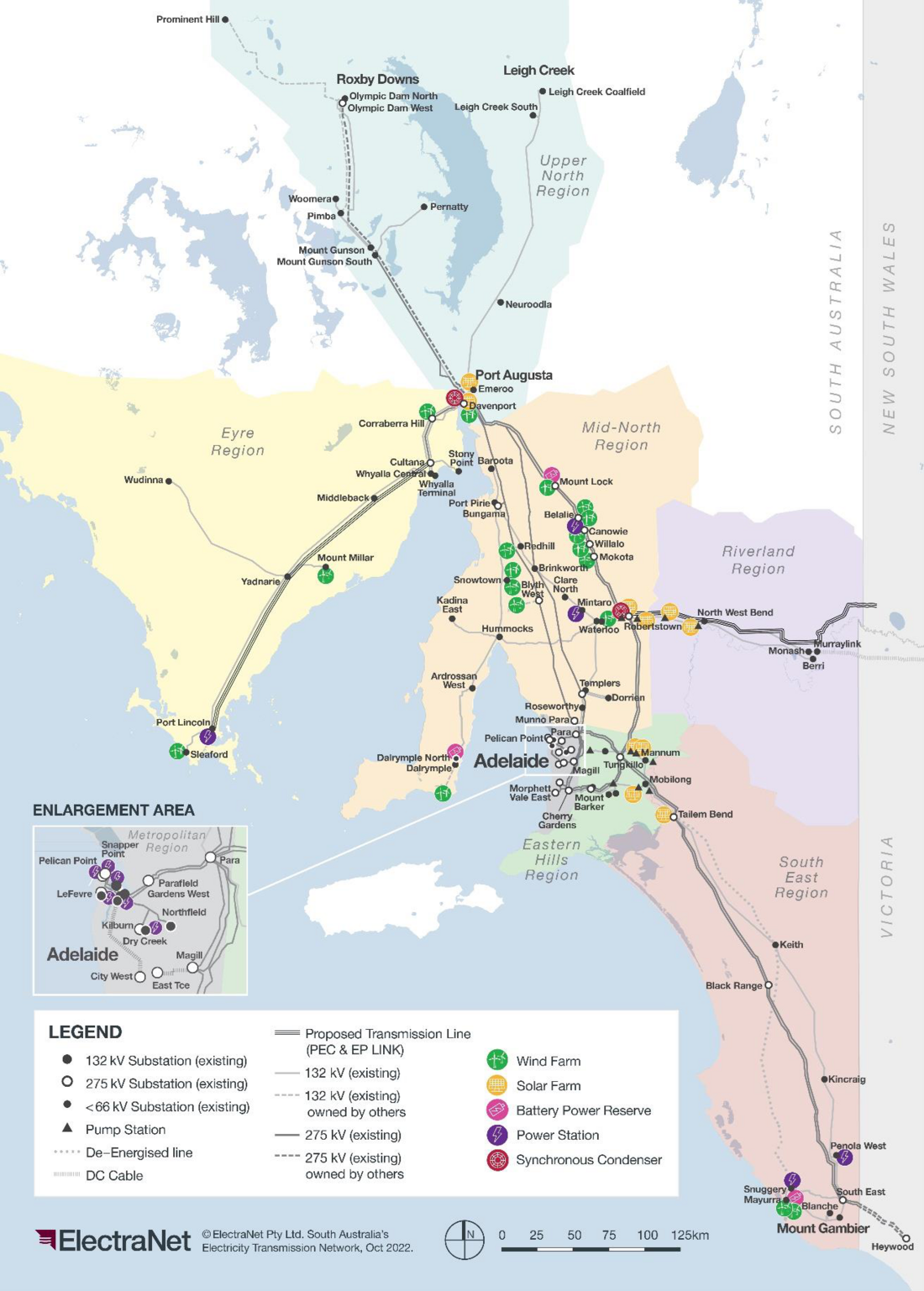
Figure 1 - Portion of the Australian NEM power system [12]
It must be noted that in GW-scale power systems such as in Figure 1, it is likely that under existing conditions, synchronous generators may still be required to cover various other facets of power system operation not covered by this investigation, including reliability needs (such as, adequate reserve), primary and secondary frequency control, management of large ramping events, and protection adequacy. However, this paper attempts to address a fundamental question: do we need a synchronous generator dispatched to sustain grid reference for grid-following IBR? If a synchronous condenser along with grid-connected IBR can instead be used to sustain grid reference, this would help reduce the reliance on synchronous generators to be running 24x7 (as long as all other aspects of system security and reliability can be met by resources either online or capable of being on standby for fast response if needed).
The remaining sections of this paper are organised as follows: Section 2 describes in detail the simulation scenarios studied, the modelling assumptions for the GW-scale power system shown in Figure 1, and the EMT case setup. Section 3 describes the success criteria. Section 4 provides the results and discussion on assessment outcomes. Section 5 investigates the role of synchronous condensers using a smaller conceptual 2-bus test system, as this provides a more simplified (yet, detailed) view of the simulation elements to clarify the problem statement. Section 6 provides a comparison of results using EMT domain tools versus positive-sequence dynamic simulation using root-mean-square (RMS) domain tools. Section 7 provides summary and conclusions. Section 8 provides references. While most of the simulations presented in this paper can be replicated using RMS domain tools, EMT simulations were used as the primary means to verify the behaviour of PLL and other protection and control system response of IBR. This is necessary as presently available positive-sequence IBR models incorporating PLL dynamics in RMS tools require further benchmarking before it can be fully adopted for studies of this nature. However, for the sake of completeness, Section 6 includes a comparison of results obtained with RMS domain tools.
2. Simulation scenarios, modelling assumptions and EMT case setup
This section describes in detail the simulation scenarios studied, modelling assumptions and the EMT case setup. The following base case assumptions were made in all scenarios studied with the portion of the GW-scale islanded power system shown in Figure 1:
- Zero synchronous generators were online in the portion of the islanded system under investigation.
- The high voltage AC interconnector between South Australia and Victoria was kept in-service before the separation event and when disconnected resulted in an electrical frequency island of the power system under investigation as shown in Figure 1, as the HVDC link is only capable of active power (MW) transfer and is not frequency responsive.
- All key high voltage transmission lines interconnecting load and generation were assumed in-service within the islanded portion, unless disconnected as part of a contingency event or disturbance.
- Transmission-connected utility-scale wind and solar generation was assumed to dispatch close to 2.2 GW, to meet required demand in the power system under investigation. Depending on the scenario investigated, the pre-disturbance load in the setup was dispatched to meet the generation and net interconnector flows.
- Transmission-connected grid-following BESS were dispatched close to zero generation or low levels to provide necessary frequency control following the disturbance.
- Synchronous condensers were assumed in-service.
Other network elements including static var compensators (SVCs) and the HVDC link were kept in-service in the base case. Additional sensitivity tests (not reported in this paper) were also conducted to account for the possibility of prior outage of these critical network elements.
2.1. Simulation Scenario 1: Loss of AC interconnector resulting in a separation event
A double line to ground fault was applied close to the AC interconnector end with subsequent tripping of the high voltage AC interconnector and the fault cleared within primary clearance time. This resulted in a separation event where the portion of the system shown in Figure 1 was electrical frequency islanded from the rest of the power system. The results for this scenario, when the AC interconnector is importing active power into the island portion, are presented in Section 4.1.
2.2. Simulation Scenario 2: Simulation of self-sufficient island portion of the system
Assuming that a separation event (due to loss of the high voltage AC interconnector) has already occurred, the impact of operating the electrical frequency islanded system highlighted in Figure 1 (in the context of grid reference) with zero online synchronous generators was simulated. In addition, a disturbance resulting in a trip of 200 MW generation loss was studied to examine the ability of synchronous condensers and grid-connected IBR to sustain the grid reference. The results for this scenario are presented in Section 4.2.
2.3. EMT Case Setup
For the scenarios mentioned above in Section 2.1 and Section 2.2, a large-scale EMT model of the power system was used, which included:
- Approximately 600 power system network buses.
- Site-specific detailed EMT models for the IBR, SVC, HVDC link and synchronous condensers.
- 275 kV and 132 kV transmission lines were modelled as distributed Bergeron PI line models [13].
- Network power transformers were modelled as three-phase transformers, including losses and leakage impedance, but excluding the topology and magnetic saturation effects.
- Load was represented as static voltage and frequency-dependent active and reactive power components, for additional details of this load model readers may refer [14]. A load relief factor of 0.5 was used in this study, meaning a 1% deviation in frequency from the nominal resulted in a load demand active power change of 0.5%.
This setup resulted in approximately 36 parallel simulation cases (IBR projects and network models) and around 1.5 hours to run a 30‑second (s) simulation on a 14-core machine. For clarity, parallel simulation cases refer to the splitting of projects in the EMT simulation platform, not the scenarios discussed in this paper.
3. Success criteria
The following success criteria were applied for all the simulations studied:
- After the separation event or contingency, the frequency should be contained within 49-51 hertz (Hz), assuming a nominal frequency of 50 Hz. The recovery and stabilisation of frequency was not considered, as this would require modelling of secondary frequency control actions such as Automatic Generation Control (AGC), which is out of scope of the EMT simulation timeframe.
- The high voltage transmission network positive-sequence RMS voltage phasor magnitude should be within 0.9 pu to 1.1 pu, under pre- and post-disturbance conditions, although a brief overvoltage above 1.1 pu is acceptable for up to 0.9 seconds (s).
- All online IBR generation should not trip or go through multiple fault ride-through sequences after the fault clearance and should return to pre-disturbance active power levels, unless tripped as part of the contingency.
- Power system oscillations (if any) in the network voltages or other quantities should be well damped and meet the halving time requirement within 5 s.
- Rate of change of frequency (RoCoF) after fault clearance should not exceed 1 Hz/s.
It should be noted that the above criteria can be further expanded, and many other success criteria can be added, however the intent of this paper and the investigation presented was to assess the notion of grid reference sustained by synchronous condensers and grid-connected IBR in the absence of synchronous generation. The above criteria provided a guideline to ensure the resulting system is not unstable.
4. Results and discussion
The results of the assessment for scenarios described in Section 2 are presented here.
4.1. Results for Scenario 1 – Loss of AC interconnector resulting in a separation event
The results for the loss of AC interconnector at t = 15 s, when importing 185 MW of active power, are shown here. As can be observed from Figure 2, the network voltages across key high voltage transmission buses remain stable and able to meet the success criteria described in Section 3, even when zero synchronous generators are online in the islanded part of the system. The speed of the synchronous condensers closely tracks with the network frequency of the islanded portion of the system and remains stable, as shown in Figure 3. While the frequency is not quite restored back to 50 Hz, due to the deficit of active power, the frequency nevertheless stabilises at around 49.25 Hz, which is within the frequency limits stated in Section 3. The response of IBR generation and BESS is shown in Figure 4. As seen, the BESS injects active power quickly to aid the frequency response within its control range, and the IBR generation of 2.2 GW is restored to the pre-disturbance level without any disconnection or undesired response.
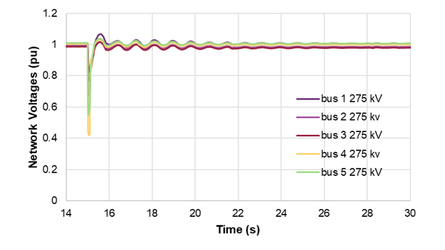
Figure 2 - Network voltages – loss of AC interconnector importing 185 MW
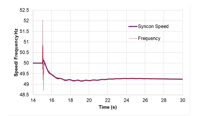
*Note: during the disturbance, the large variation in frequency transient should be ignored as this is a result of EMT numerical computation.
Figure 3 - Synchronous condenser rotor speed and network frequency – loss of AC interconnector importing 185 MW
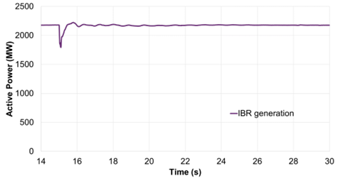
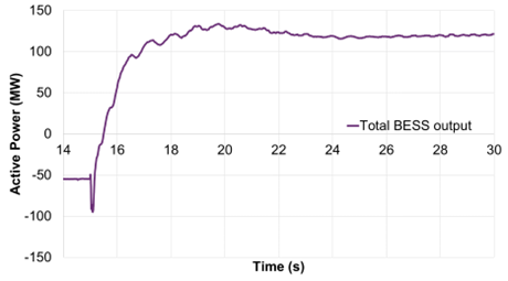
Figure 4 - IBR and BESS active power – loss of AC interconnector importing 185 MW
4.2. Results for Scenario 2 – Simulation of self-sufficient island portion of the system
With the portion of the system shown in Figure 1 electrical frequency islanded, a contingency trip of a 200 MW generation loss was simulated at t =15 s. As seen in Figure 5, the network voltages at key 275 kV buses within the island remain stable. The network frequency and synchronous condenser speed as seen in Figure 6 track very closely similar to Scenario 1, with the frequency settling around 49.15 Hz, which is within the limits stated in Section 3. This shows that the system remains stable from the perspective of grid reference, despite the loss of a large wind farm. The response of remaining IBR generation, shown in Figure 7, also remains stable with the IBR restored to pre-disturbance output levels (less 200 MW). The BESS response shown in Figure 7 also remains stable, with the BESS injecting active power to aid in the frequency response within its control range. The BESS in this scenario was dispatched close to 0 MW during pre-disturbance conditions to ensure sufficient headroom for response following the trip of 200 MW of generation.
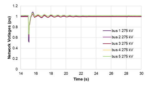
Figure 5 - Network voltages – trip of 200 MW wind farm within island
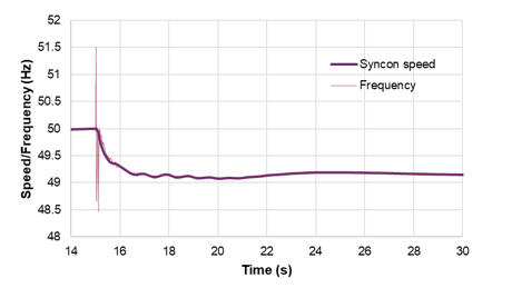
*Note: during the disturbance, the large variation in frequency transient should be ignored as this is a result of EMT numerical computation.
figure 6 - Synchronous condenser rotor speed and network frequency – trip of 200 MW generation within island
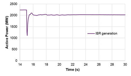
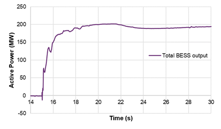
Figure 7 - IBR and BESS active power – trip of 200 MW generation within island
5. Investigation of grid reference using a conceptual 2-bus test system
To further investigate the notion of grid reference provided by a synchronous condenser, a conceptual 2-bus test system shown in Figure 8 was simulated.

Figure 8 - Conceptual 2-bus test system – IBR serving load with synchronous condenser
The conceptual 2-bus test system comprises a synchronous condenser, a 65 MW type-4 (full-scale converter) wind farm (shown as IBR) and a load of approximately 65 MW with 0.9 power factor. The IBR is connected to the load via a transmission line modelled as distributed PI (Bergeron line model). An ideal voltage source is used to initialise this setup and eventually is disconnected in the simulations at t = 11 s to demonstrate the notion of grid reference through the conceptual 2-bus test system.
As seen in Figure 9 and Figure 10, the network voltage, network frequency and active power generated by the IBR in this test system remains stable even upon disconnection of the ideal voltage source at t = 11 s, provided the synchronous condenser is kept in-service. If the synchronous condenser is taken out-of-service, the system collapses, as expected.
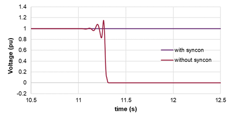
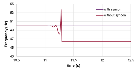
Figure 9 - Network voltage and frequency in the conceptual 2-bus test system
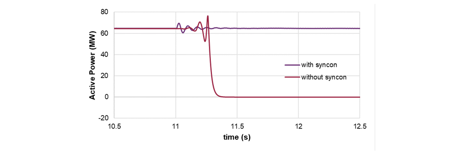
Figure 10 - Network voltage and frequency in the conceptual 2-bus test system
This demonstrates the notion of synchronous condensers’ ability to sustain a grid reference for grid-following IBR to latch-on based on EMT simulations. It must be noted, however, that including a grid-following BESS instead of a type-4 wind farm would have resulted in better frequency control, due to the superior frequency response capability of a BESS compared to a type-4 wind farm. Further, the results are similar irrespective of the power supply design requirements for the automatic voltage regulator (AVR) of the synchronous condenser; i.e., whether it is auxiliary grid fed or permanent magnet generator based independent fed power supply, the synchronous condenser is capable of sustaining a grid reference along with the grid-connected IBR. While not reported in this paper, similar results for the above conceptual system were also noted for other grid-following IBR technologies, such as a type-3 wind farm, a solar farm and a BESS.
Additional sensitivity was studied by replacing the synchronous condenser in Figure 8 of the conceptual 2-bus test system with a grid-following SVC and STATCOM, respectively. The breaker connecting the ideal voltage source in Figure 8 was disconnected at t = 20 s. As seen from Figure 11, the network voltages and frequency collapse with the use of grid-following SVC and STATCOM instead of a synchronous condenser, as they cannot sustain a rotating grid reference. The reactive power contribution of each of these devices is shown in Figure 12. As can be observed, the grid-following SVC and STATCOM provide a response within tens of milliseconds, but the response cannot be sustained as the lack of grid reference forces their output to zero, upon the disconnection of the ideal voltage source in Figure 8.
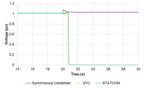
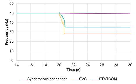
Figure 11 - Voltage and frequency – sensitivity of grid-following SVC and STATCOM devices with 2-bus test system
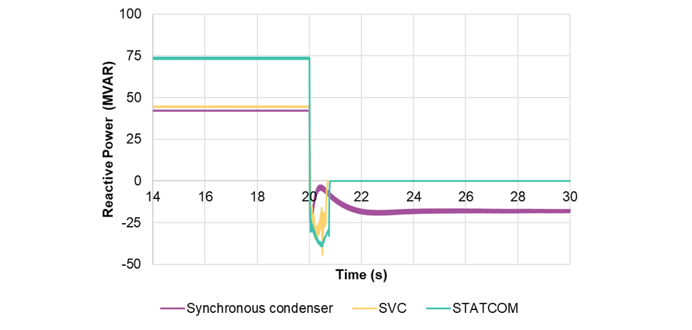
Figure 12 - Reactive power – sensitivity of grid-following SVC and STATCOM devices with 2-bus test system
6. Comparison with RMS modelling
This section presents a comparison of the results using RMS and EMT domain tools obtained following the loss of AC interconnector at t= 15 s when importing around 185 MW of active power resulting in an island formation. As can be seen in Figure 13 and Figure 14, RMS domain tools also provide a similar response. Thus, the notion of sustaining a grid reference using IBR and synchronous condensers was verified using both RMS and EMT modelling platforms.
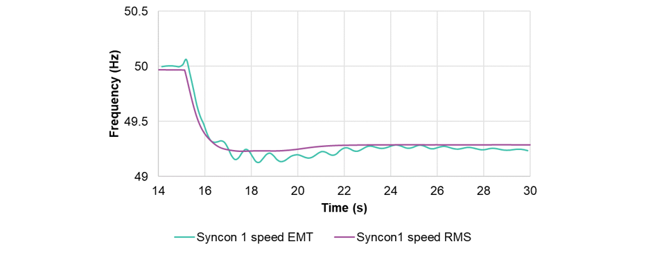
Figure 13 - Synchronous condenser speed – comparison between EMT and RMS tools
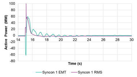
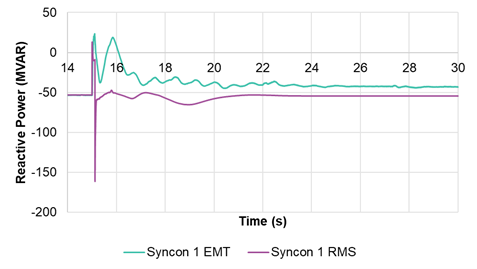
Figure 14 - Synchronous condenser active and reactive power responses – comparison between EMT and RMS tools
7. Conclusions
This paper has investigated the simulation of a GW-scale power system without synchronous generators using detailed EMT models of the grid-following IBR plants (including BESS), SVC, HVDC and synchronous condensers. The role of sufficiently sized and properly sited synchronous condensers along with grid-connected IBR in sustaining a grid reference was shown to be vital in the absence of synchronous generators in the system. The simulation scenarios tested have shown that the network voltages and frequency (including speed of the synchronous condenser) remained stable following a separation from the rest of the power system. Further, the active power response of grid-following IBR (including BESS) was shown to be satisfactory without any adverse impact such as disconnection from the grid or unstable response due to lack of a grid reference. The network voltages and frequency under islanded system conditions remained stable without synchronous generators despite the simulated contingency trip of a large wind farm. Results based on a conceptual 2-bus test system were used to further highlight the role of synchronous condensers, where without the synchronous condensers the grid-following IBR did not have a grid reference to latch-on, which resulted in a network collapse, as expected.
A number of sensitivity test scenarios (not reported in this paper) – such as gradual load ramps as seen during power system operations (including dynamic motor load modelling to simulate motor starts), and prior outage of several critical network elements – were also studied in the GW-scale power system without synchronous generators. No adverse impact was observed, and the network voltages and frequency remained satisfactory.
The presence of a grid-following BESS with sufficient head and foot room was shown to provide frequency control within its range to aid in the frequency response following the simulated disturbances.
The next steps planned in this work would include a physical test on a small sub-network of the actual power system with grid-following IBR and a few synchronous condensers, to demonstrate the notion of synchronous condensers’ ability to sustain a grid reference for grid-following IBR to latch-on without the need for synchronous generators.
References
- NEM Market Suspension
- NEM Market Suspension and Operational Challenges in June 2022, AEMO incident report, published online
- IEEE, “Power system operation with a high share of inverter-based resources: The Australian Experience”, IEEE Power & Energy Magazine, Vol 19, no. 5, September/ October 2021
- Deepak Ramasubramanian, Pouyan Pourbeik, Evangelos Farantatos, Anish Gaikwad, "Simulation of 100% Inverter-Based Resource Grids with Positive Sequence Modelling", IEEE Electrification Magazine, vol. 9, issue 2, June 2021.
- Nan Xue, et al., “Dynamic security optimization for N-1 secure operation of Hawaii island system with 100% inverter-based resources”, IEEE Transactions on Smart Grid, vol. 13, issue 5, December 2021.
- Mario Ndreko, Sven Ruberg, Wilhelm Winter, “Grid forming control scheme for power systems with up to 100% power electronic interfaced generation: a case study on Great Britain test system”, IET Renewable Power Generation, vol. 14, issues 8, pp. 1268 – 1281, December 2020.
- Rossano Musca, Antony Vasile, Gaetano Zizzo, “Grid-forming converters. A critical review of pilot projects and demonstrators,” Renewable and Sustainable Energy Reviews, Vol. 165, 2022.
- SMA projects
- Siemens Gamesa projects
- Duke Energy Projects
- NREL Projects
- SA Transmission Network Voltage Control, PSCR-EC.11645-Transmission-Network-Voltage-Control.pdf (electranet.com.au)
- Hermann W. Dommell, “EMTP Theory Book”, Portland, Oregon, USA, Bonneville Power Administration, 1986.
- Prabha Kundur, “Power System Stability and Control”, Chapter 7, McGraw Hill, 1994.
