Determination of the Soil-Foundation Stiffnesses in Lattice Tower Structures for Numerical Modeling Applications
Authors
M. BAHARI, S. LANGLOIS - Département de génie civil et de génie du bâtiment, Université de Sherbrooke, Canada
S. PRUD’HOMME - Hydro-Québec, Canada

Summary
Assuming no soil-structure interaction and ignoring the flexibility of soil-foundation system, the foundation of lattice tower structures has been traditionally considered as a fixed base in practical engineering design works. However, as the lattice tower structures are subjected to complex dynamic loading condition and also to specific nonlinear behaviours, the substructure performance and consequently overall tower response under static and dynamic loads are dependent on the stiffness and damping characteristics of the soil, foundation, and the way in which they interact. Reviewing the literature, one approach to predict the soil/foundation rigidity in different rotational/translational directions in numerical modeling methods is implementation of analytical equations in the form of impedance functions. Nevertheless, the suggested equations do not consider the foundation stiffness, since the foundation itself has been considered as a rigid body in the available theoretical and experimental studies. In addition, the type of the studied foundations are typically common concrete foundations, whereas grillage foundations are widely used in the case of lattice tower structures for transmission line applications. Moreover, the recommended solutions do not comprise pullout stiffness of the soil-foundation system. The objective of this paper is to propose a methodology to evaluate the stiffness along six degrees of freedom for both concrete and grillage foundations of steel lattice towers. Accordingly, at the first step, analytical equations for stiffness components have been introduced, and then experimental pullout tests of several grillage and concrete foundations, performed by industrial partners, in different soil types, have been studied to estimate the pullout stiffness of the soil-foundation system based on the developed normalized force-displacement curves. The normalized curves have been extracted based on the curve fitting of all tests of the same soil type. The rest and main part of the study, tries to develop and predict the stiffness of the combined system of soil-foundation in other degrees of translational and rotational movements. To do so, two real lattice towers with different soil types and characteristics have been considered and the stiffness of the soil-foundation system has been predicted based on the suggested solution for the real designed foundations of each tower. The methodology combines the soil spring stiffnesses with foundation stiffness in developed finite element models. The results are symmetrical six by six stiffness matrix with coupled terms of each specific foundation and soil type. The influence of soil type and compactness as well as foundation type is discussed.
Keywords
Grillage foundations, Lattice tower structures, Pullout stiffness, Soil-foundation stiffness, Stiffness matrix1. Introduction
Providing a reliable transmission line network has increased during last years the need of resilient designing for related infrastructures in this field [1], [2]. Various researches have been performed to study lattice tower structures behaviour under particular loading conditions which these structures could experience during wind loads, conductor breakage and also extreme weather conditions, as well as static loading states [3-6] . However, to have a comprehensive understanding of the overall structural behaviour and response, ultimate resistance, and also final failure mode and structural capacity, the flexibility effects of the substructural parts including soil-foundation system should also come into account, while performing advanced numerical modeling of the whole structure. That is because the overall foundation and consequently whole structure performance is dependent on the relative stiffness and damping properties of the foundation and soil medium [4,7-9]. For instance, soil springs which are used to consider soil-structure interaction, could reduce the tower’s natural frequency and can increase the displacement response of the whole tower structure [10,11]. Nevertheless, in the case of lattice tower structures, in which incomprehensive design knowledge could cause serious damage to transmission line system and result in power outages, few studies have tried to combine the behavior of tower structure and soil/foundation in a total system, considering soil-structure interaction [3]. On the other hand, the effect of differential foundation settlement on redistribution of forces of the lattice tower under different loading scenarios could affect the stability of the whole structure [12], while is directly dependent on considering soil-structure interaction. The occurrence of differential/nonuniform settlements increases the importance of soil-structure interaction in case of lattice tower structures, experiencing significant dynamic loads. Moreover, nonlinearity behavior due to material and geometrical issues such as large displacements, bolt slippage, and eccentricity of connections could significantly affect the stiffness of the tower [12-15] and would have duplicate effects while the flexibility of the foundation comes into account.
Different approaches have been assessed in the literature in evaluating soil/foundation stiffness and their interaction and consequences on the structure. One methodology to consider the effect of soil-structure interaction is to define impedance functions [9, 11, 16], in the forms of springs and dashpots as interface elements between structure and soil-foundation system. These equations have been generally developed based on the foundation geometry and soil parameters. The detailed study and calculations of such relations could be found in the works of [17-20].
However, it seems that the foundation in these studies has been supposed as a rigid body, which means the flexibility of the foundation has not come into account in definition of total stiffness of soil-foundation system. Therefore, as there are different foundation types, widely used in lattice tower structures, such as surface inverted t-type concrete and grillage foundations, the realistic implementation of available impedance equations necessitates consideration of foundation flexibility itself in determination of the total stiffness of the system.
In addition, the accessible equations do not contain relations for pullout stiffness of the soil-foundation system. As the lattice towers can typically experience tension forces in their legs and connected foundations under loads such as wind or conductor breakage, it is essential to have realistic estimation of foundation’s pullout rigidity. Therefore, the objective of this paper is to propose a methodology to evaluate the stiffness along six degrees of freedom for both concrete and grillage foundations of steel lattice towers. It should be noted that only stiffnesses are evaluated and the study of the complete impedance functions of the foundation including the damping properties is out of scope of the work.
Accordingly, stiffnesses in both compression and uplift are evaluated for the axial direction. The stiffnesses based on the available impedance functions have been first introduced and then to fulfill their deficiency in uplift direction, pullout experimental tests of grillage and concrete foundations have been investigated and three-linear normalized curves have been produced and suggested for each different soil types.
The rest of the research work investigates the realistic and practical estimation of the soil-foundation system stiffness in other degrees of freedom, and suggests the calculation method for different types of foundations such as concrete or grillage, in different soil categories such as granular and cohesive. To do so, two real specific lattice towers, commonly used by industrial partners, have been selected and depending on different soil parameters, in each soil category, the required grillage and concrete foundations have been designed. The available impedance equations of [18] have been applied to estimate soil stiffnesses in different directions. As lattice towers transfers mostly tension and compression forces to the foundations, the calculated stiffnesses in translational movements have been converted to soil spring stiffnesses by solving rigid body motion of the solid foundation in the corresponding translational directions. The calculated spring stiffnesses have been implemented in numerical finite element models of rigid and flexible foundations, in which the soil springs in different translational directions have been simultaneously assigned to the foundation to calculate the total combined soil-foundation stiffness.
Finally, a six-degrees of freedom stiffness matrix of the soil-foundation system of each designed foundation of towers could be calculated for each compression and tension leg of the tower to allow its implementation in numerical modeling of the entire structure. The stiffness matrix is a six by six symmetrical one, in which the coupled terms have been also calculated based on the developed finite element models.
2. Lattice Towers, Soil and Foundation Types
The selected lattice towers will be presented in this part as well as different soil types and parameters.
2.1. H2 and BSG Towers
To conduct a practical and realistic study, two real full-scale types of lattice tower structures have been selected. The towers are widely used by the research group partners, Hydro-Québec of Canada and RTE of France. The H2 tower, as shown in figure 1-a, is a single circuit tower designed for 63/90 kV transmission lines built in France. The total height of the structure is 32 m with a square base of 3.4 m X 3.4 m. The tower has similar faces in each four planes with a staggered triangular bracing pattern.
The BSG tower, as shown in figure 1-b is a 120 kV transmission lattice tower used by Hydro-Québec, which the foundation type is normally grillage. The possible maximum height of the tower is 48.02 m with a base dimension of 13.1 m X 13.1 m.
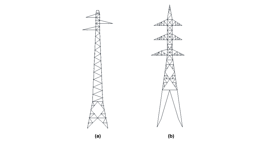
Figure 1 - a: H2 tower, b: BSG tower
2.2. Soil types and Parameters
In order to have a comprehensive investigation on flexibility/rigidity of soil-foundation system, different soil types including cohesive (clay) and granular (sand) have been selected. Each soil category has two different soil parameters, representing compact and loose types. Table 1 defines soil types and corresponding parameters. By reviewing soil parameters of all available experimental tests of industrial partners (Hydro-Québec and RTE), the following characteristics have been selected as representative of each soil type. Classical soil mechanics references [21, 22] are used to categorize each soil type in compact and loose types. To estimate missing soil parameters such as G (shear modulus), suggested relations in [21-23] have been utilized. In Table 1, C', φ' and Cuu, φuu are respectively cohesive parameter and angle of friction of the soil in drained and undrained conditions. γ, N, G, and ν are respectively unit weight, SPT number, shear modulus and Poisson factor of the soil.
| Type | C' (kPa) | Cuu (kPa) | Φ (deg.)' | φuu (deg.) | γ (kN/m3) | N | G (kPa) | ν |
|---|---|---|---|---|---|---|---|---|
| Sand (compact) | 15 | - | 31 | - | 19.5 | 35 | 158,890 | 0.30 |
| Sand (loose) | 0 | - | 29 | - | 16.5 | 3 | 27,008 | 0.16 |
| Clay (compact) | 20 | 55 | 20 | 5 | 18.2 | 22 | 105,445 | 0.30 |
| Clay (loose) | 12 | 32 | 11 | 2 | 16.4 | 6 | 13,750 | 0.10 |
2.3. Foundation Types and Design
It has been supposed that each tower (H2 and BSG) could possibly have concrete or grillage foundation. Then, considering the resulted forces on each tower’s foundation due to the loading condition and soil properties, the required grillage and concrete foundation have been designed for each tower-soil category. That is, the dimension of each foundation type provides the required resistance for the corresponding towers’ foundations forces. Each foundation type should be designed against compression and pullout forces. The main design of the foundation is against pullout forces, which relevant designing norms of industrial partners including [24-27] have been used respectively for grillage and concrete foundation types. For the compression forces, the allowable soil pressure has been calculated according to the classical equations of [28].
Considering all soil and foundation types, sixteen different foundations could be designed for the two towers. However, to avoid providing lots of information and also to be able to compare different flexibility of foundations, only for one specific soil type (sand loose) both grillage and concrete foundations have been designed for the two towers. On the other hand, as the grillage foundations are in more importance and interests of industrial partners and could have significant effects in total combined stiffness of the soil-foundation, three other grillage foundations have been designed only for H2 tower, corresponding to the three other presented soil types. Therefore, seven foundations have been presented and discussed. The characteristics of the foundations are listed in Table 2. L, B, and D are respectively length, width and depth of the embedment of the foundation.
| No | Tower Type | Foundation Type | Soil Type | L (m) | B (m) | D (m) |
| 1 | H2 | Grillage | Sand Loose | 1.40 | 1.40 | 1.70 |
|---|---|---|---|---|---|---|
| 2 | H2 | Concrete | 1.20 | 1.20 | 2.00 | |
| 3 | BSG | Grillage | 3.79 | 3.20 | 3.00 | |
| 4 | BSG | Concrete | 3.20 | 3.20 | 3.20 | |
| 5 | H2 | Grillage | Sand compact | 1.20 | 1.20 | 1.80 |
| 6 | H2 | Grillage | Clay compact | 1.30 | 1.30 | 1.70 |
| 7 | H2 | Grillage | Clay loose | 1.80 | 1.80 | 1.80 |
Figure 2 Illustrates samples of each designed grillage and concrete foundation.
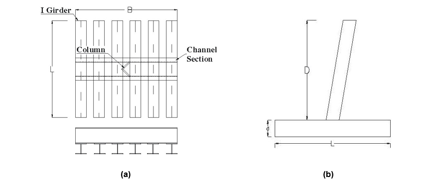
Figure 2 - sample designed foundations with inclined column, a: grillage foundation, b: concrete foundation
3. Evaluation of Soil/Soil-Foundation System Stiffness
The impedance functions, suggested by [18] have been utilized to estimate the stiffness of the presented soil-foundation categories, based on the foundation dimensions and soil properties. The first following section discusses Gazetas equations, while the subsequent sections introduce the uplift stiffness of the foundation.
3.1. Theoretical Stiffness of Foundation
Gazetas’s [18] equations for foundation rigidity comprise six degrees of freedom including X and Y horizontal displacements, compression in Z direction, and three rotational movement about X,Y, and Z axes. In this section these six stiffnesses have been calculated for each foundation.
The relation for stiffness of each degree of freedom could be found in [18,29]. Shear modulus (G) and Poisson ratio (ν) of the soil are the main characteristics of the soil in these equations. Calculated stiffness in each direction should be modified by a factor (η) to consider the depth of embedment (D) of the foundation. Figure 3 shows the foundation in general form in XY plane and circumscribe rectangle of the foundation.

Figure 3 - General form of the foundation in XY plane in Gazetas’ equations
Table 3 presents the calculation results of stiffness for six degrees of freedom for each foundation in kN and m. The theoretical relations and sample calculation for a specific soil-foundation type is presented in appendix 1 of this paper.
2L and 2B are length and width of foundation as illustrated in Figure 3. kx, ky, and kz are translational stiffnesses, and kxx, kyy, and kzz are rotational stiffnesses respectively along with axes x, y, and z of the foundation.
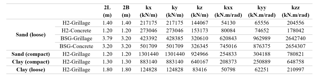
Table 3 - Stiffness of the soil part of designed foundation in for each soil-foundation system
3.2. Uplift Stiffness Estimation
As discussed before, Gazetas [18] impedance equations lack in prediction of pullout stiffness. Therefore, to have a complete estimation of all stiffness components, the tension stiffness of the foundation should also be estimated. The experimental pullout tests on grillage and concrete foundations, conducted by Hydro-Québec [30] and RTE [31] have been used and investigated to study and predict the uplift stiffness.
3.2.1. Pullout Tests of Grillage Foundations
The pullout experiments on grillage full-scale foundations of lattice towers which have been performed by Hydro-Québec [30] in different soil types have been investigated. The tests were run on foundations from towers that were recently dismantled. The size of the foundations and their resistance reflect the applicable design code of their construction years. The experiments have been performed by applying uplift force on the foundation until rupture of the backfill soil. The results of the tests have been presented in the form of force-displacement curves. Figure 4 shows a sample foundation of the tests. The properties of the grillages and soil parameters of each soil category have been summarized in Tables 4 and 5.
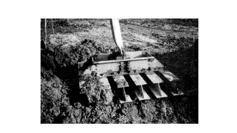
Figure 4 - Full-scale grillage foundation of lattice towers after pullout test [28]
| Tower | 2L (m) | 2B (m) | D (m) | γ' (kN/m3) | Φ' (°) |
|---|---|---|---|---|---|
4-2 | 1.473 | 1.372 | 2.642 | 9.5 | 29 |
4-4 | 1.473 | 1.372 | 2.950 | 9.5 | 29 |
6-2 | 1.473 | 1.372 | 2.705 | 9.5 | 29 |
6-4 | 1.473 | 1.372 | 2.667 | 9.5 | 29 |
17-3 | 0.457 | 0.737 | 1.803 | 9.5 | 29 |
17-4 | 0.457 | 0.737 | 2.108 | 9.5 | 29 |
18-3 | 0.457 | 0.737 | 1.727 | 12.0 | 29 |
18-4 | 0.457 | 0.737 | 2.133 | 12.0 | 29 |
71-A | 1.219 | 0.686 | 2.388 | 10.5 | 30 |
71-B | 1.219 | 0.686 | 2.388 | 10.5 | 30 |
72-1 | 1.473 | 1.372 | 2.997 | 9.5 | 30 |
72-2 | 1.473 | 1.372 | 3.048 | 9.5 | 30 |
73-1 | 1.473 | 1.372 | 2.972 | 9.5 | 30 |
73-3 | 1.473 | 1.372 | 2.972 | 9.5 | 30 |
89-1 | 1.295 | 0.914 | 3.124 | 9.5 | 30 |
89-3 | 1.295 | 0.914 | 3.136 | 9.5 | 32 |
2L and 2B are length and width of the grillage foundation and D is depth of the soil on top of the grillage. γ' and Φ' are respectively volumetric weight and angle of friction of the soil in drained condition, which have been measured from the soil sample of each test.
| Tower | L (m) | B (m) | D (m) | Cu,ave. (kPa) | Cu,grillage (kPa) | γSat (kN/m3) |
|---|---|---|---|---|---|---|
27-1 | 1.295 | 0.914 | 2.845 | 23 | 32 | 15.6 |
27-4 | 1.295 | 0.914 | 2.794 | 32 | 48 | 14.6 |
49-3 | 1.905 | 1.219 | 3.048 | 29 | 32 | 16.4 |
50-3 | 1.905 | 1.219 | 3.100 | 34 | 42 | 15.8 |
54-4 | 1.905 | 1.219 | 3.100 | 31 | 20 | 15.5 |
57-1 | 1.905 | 1.219 | 2.997 | 42 | 37 | 16.6 |
58-2 | 1.295 | 0.914 | 2.845 | 30 | 37 | 16.9 |
74-B | 1.219 | 0.686 | 2.388 | 36 | 14 | 16.2 |
80-A | 1.219 | 0.686 | 2.388 | 42 | 14 | 16.1 |
80-C | 1.219 | 0.686 | 2.388 | 38 | 15 | 16.1 |
90-1 | 1.295 | 0.914 | 2.959 | 24 | 21 | 16.0 |
90-2 | 1.295 | 0.914 | 2.921 | 19 | 17 | 15.8 |
96-1 | 1.295 | 0.914 | 2.743 | 48 | 48 | 15.9 |
96-4 | 1.295 | 0.914 | 2.642 | 27 | 84 | 18.9 |
110-1 | 1.295 | 0.914 | 3.050 | 29 | 37 | 17.7 |
Cu,ave is average cohesion parameter of the native soil and Cu,grillage is the cohesion parameter of the back fill soil on the top of the grillage, which have been measured experimentally for the soil of each specific pullout test.
3.2.2. Normalization of the Force-Displacement Curves
If force-displacement points from all available tests of the same soil type are plotted in one graph, a scattered cloud of points appears as illustrated in Figures 5 and 6 for sand and cohesive soil respectively.
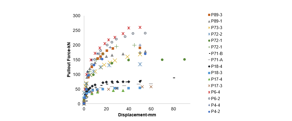
Figure 5 - Force-displacement results of all pullout tests of grillage foundations in sand soils
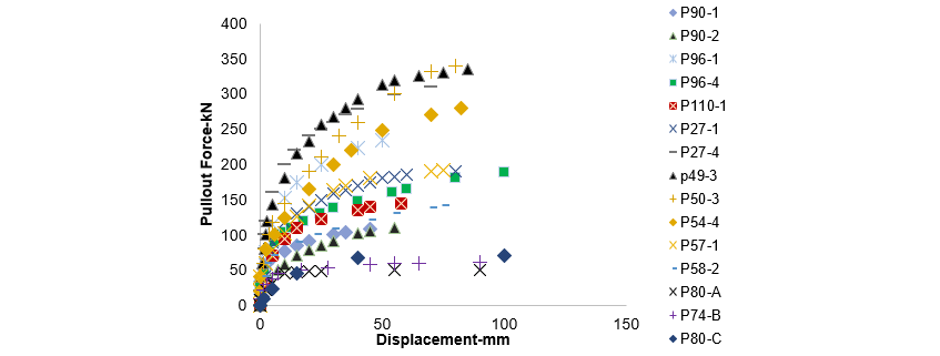
Figure 6 - Force-displacement results of all pullout tests of grillage foundations in cohesive soils
To regroup all available test data, and also consider soil properties and foundation geometry, a normalization, in accordance with the one presented in [31], has been performed for both the displacement and the force axes of the curve. That is, the displacement is normalized by the depth of the foundation (z/D), where z is the vertical displacement from experiment and D is the depth of embedment of the foundation. Similarly, the force is normalized by the measured rupture resistance (Q/Qm), where Q is the vertical force applied in experiment and Qm or Qu or is the measured rupture resistance. The results of normalization for the two soil types are presented in Figures 7 and 8. It could be observed that the normalized data points are now regrouped and share similar pattern. The normalized force-displacement curves could then be used to replace the axial stiffnesses in the case of foundation uplift. It should be noted that, unlike the equations of Gazetas, the flexibility of the foundation is integrated in this evaluation of the stiffness. Besides, a nonlinear behaviour of the soil-foundation system under uplift force is observed, which could be subsequently considered in advanced numerical modeling of the towers and foundations. However, to do so, a nonlinear curve should be fitted through the graphs of figures 7 and 8. This is done in the next subsection.

Figure 7 - Normalized force-displacement curve of all pullout tests of grillage foundations in sand soils
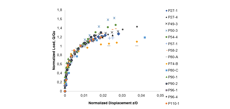
Figure 8 - Normalized force-displacement curve of all pullout tests of grillage foundations in cohesive soils
3.2.3. Definition of Normalized Three-Linear Force-Displacement Curves
The purpose of this section of the study is to estimate the uplift stiffness of foundations and corresponding soils under pullout axial forces. To do so, normalized experimental force-displacement curves have been replicated with a three-linear curve, representing three different behavioural phases of the soil-foundation system under uplift force: elastic, transition phase and plastic.
3.2.3.1. Curve Fitting for Three-Linear Curves
Three uplift rigidities representing elastic, transition phase and plastic deformation of a grillage foundation, for two types of soils, have been characterized through curve fitting of three-linear functions. Illustrated in Figure 9, k*1 is the first slope of the normalized curve, starting from zero normalized displacement until Δ*1. k*2 starts from the end of k*1 until Δ*2. And k*3 continues k*2 up to the maximum point of the measured normalized displacement corresponding to a measured maximum force. The values after the maximum force have been removed from raw experimental data, as the measured force decreases after this point with the increase in displacement.
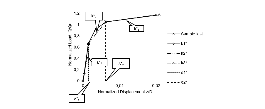
Figure 9 - Three-linear normalized curve for a sample test in sand soils
Then, developing a Python code, a curve fitting evaluation has been made for the normalized experimental data of each soil type. Accordingly, five parameters including k*1, k*2, k*3, Δ*1, and Δ*2 have been calculated. Figures 10 and 11 illustrate final normalized three-linear curves of normalized force-displacement test results. These five normalized parameters are listed in table 6.
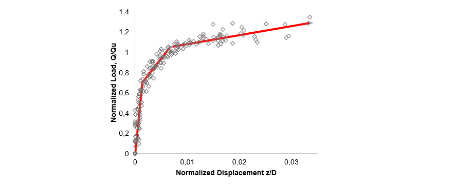
Figure 10 - Three-linear normalized curve of all sand tests of grillage foundations
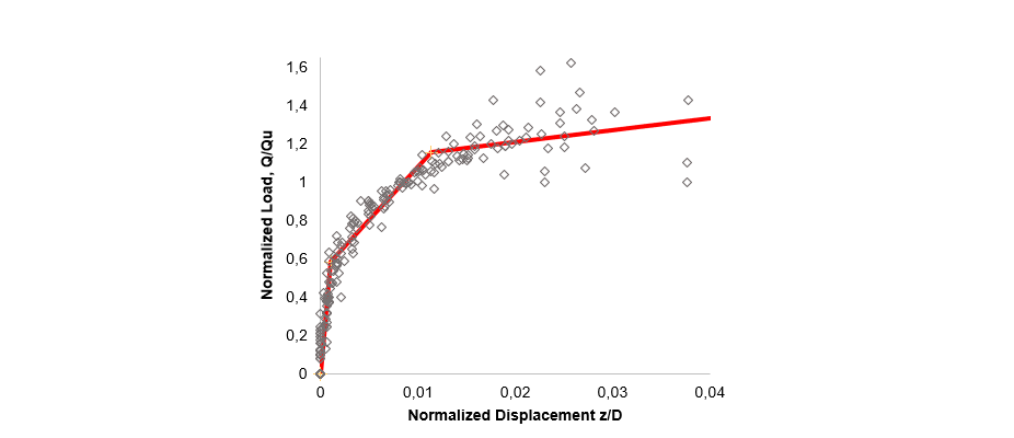
Figure 11 - Three-linear normalized curve of all cohesive of grillage foundations
| Soil Type |
| ||||
Sand | 499.339 | 65.360 | 8.950 | 0.00141 | 0.00677 |
Clay (Cohesive soil) | 535.104 | 55.426 | 6.258 | 0.00109 | 0.01137 |
Therefore, knowing embedment depth and calculating the Qm theoretically, the three-linear force-displacement curve of an arbitrary grillage foundation under pullout force could be generated implementing values from Table 6. To calculate Qm (Qc), as verified in [32], the Kulhawy method [33,34] for granular soils and shear method for cohesive soils give the more realistic estimations and could be applied in calculation of each k. Once Qm (Qc) is calculated, k* must be multiplied by Qc/D and Δ* multiplied by D in order to calculate the specific pullout-force-displacement curve of the foundation.
3.2.4. Normalized Curves of Concrete Foundations
The normalized curves have been defined and presented in the previous section are developed based on the uplift tests on grillage foundations. The same process is performed on available experimental tests of RTE [31] on concrete foundations with different soil types. Generally, the soil in these tests seems denser than for grillage tests in each type.
The characteristics of foundations and soil properties in experimental tests are listed in Tables 7 and 8.
| Pylon | D (m) | L (m) | B (m) | C' (kPa) | φ' (deg.) | γ (kN/m3) |
S05 | 2.0 | 1.6 | 1.6 | 12.0 | 29 | 19.5 |
S09 | 2.4 | 2.0 | 2.0 | 11.7 | 30 | 19.5 |
S09B | 2.4 | 1.6 | 1.6 | 11.7 | 30 | 19.5 |
S13 | 2.8 | 2.6 | 2.6 | 11.4 | 31 | 19.5 |
B-1er | 2.2 | 1.2 | 1.2 | 20.0 | 45 | 19.0 |
B-2e | 1.9 | 1.2 | 1.2 | 15.0 | 45 | 19.0 |
G-1er | 2.5 | 1.6 | 1.6 | 5.0 | 27 | 18.0 |
G-2e | 2.5 | 1.5 | 1.0 | 5.0 | 27 | 18.0 |
| Foundation | D (m) | B (m) | L (m) | γave (kN/m3) | Cuu (kPa) | C' (kPa) | φuu (deg.) | φ' (deg.) |
B | 2.4 | 1.6 | 1.6 | 18.2 | 55 | 20 | 5 | 20 |
C | 1.8 | 2.0 | 2.0 | 18.2 | 55 | 20 | 5 | 20 |
Similar to grillage foundations, the three-linear normalized curves are developed and presented in Figures 12 and 13.
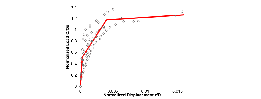
Figure 12 - Three-linear normalized curve of sand tests on concrete foundations
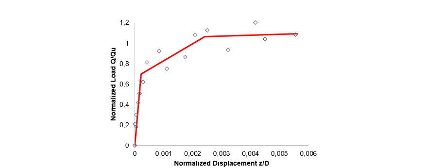
Figure 13 - Three-linear normalized curve of cohesive tests on concrete foundations
Table 9, similar to Table 6, presents five required parameters in prediction of pullout stiffness of soil-foundation system in concrete foundation cases.
| Soil Type | (Const.) | (Const.) | (Const.) | (m/m) | (m/m) |
Sand | 1818.912 | 176.072 | 7.318 | 282e-4 | 403e-3 |
Clay (Cohesive soil) | 3226.410 | 164.474 | 9.096 | 2e-4 | 24e-3 |
Similar to grillage foundations, the pullout resistance of the concrete foundations (Qc) is needed to be calculated. Then each k* must be multiplied by Qc/D to produce corresponding stiffness of each phase. To calculate Qc the suggested method in [26, 31] could be used.
Now that the methodology to estimate uplift stiffness has been defined and presented, the five values in tables 6 and 9 could be used in order to calculate the pullout stiffness of the desired soil-foundation groups.
4. Stiffness of Combined Soil-Foundation System
As the foundation in the calculated stiffnesses based on Gazetas equations has been supposed a rigid body, the flexibility of the foundation, itself has not come into account in prediction of the stiffness. Therefore, the resulting stiffness in Table 6 represents the stiffness of the soil corresponding to that foundation’s geometry. In this section, the soil springs have been assigned in numerical finite element models of the flexible foundation to estimate the combined stiffness of the soil-foundation system. The following section explains the methodology of calculating spring stiffness in each translation movements to be applied to the corresponding numerical model of flexible foundation.
4.1. Rigid Body Motion Methodology
Considering a rigid foundation, the stiffness of the soil springs in each degree of freedom have been calculated so that to produce the same stiffness of the soil, which were estimated through Gazetas equations (Table 3). Then, the calculated soil spring stiffnesses have been assigned, this time, to a flexible foundation finite element model to predict the total stiffness of the soil and flexible foundation. The following explains the calculation methodology of rigid body motion for each translational degree of freedom in X, Y, Z directions. The approach for the vertical degree of freedom (Z) is detailed.
Imposing a small vertical displacement (Δ) in Z axis of the rigid foundation at the top point of its connected column, when all 6 degrees of freedom are blocked, vertical forces would be produced at the springs on the base of the foundation and connected column. The springs represent the surrounding soil of the foundation and column. Calculating total force and doing a reverse solution of the rigid-foundation-soil system, the stiffness of the soil springs to apply to the model’s nodes could be calculated. Figure 14-a shows the rigid foundation and soil springs which will experience the small displacement of Δ. Figure 14-b shows deformed shape of solid foundation and resulted forces.
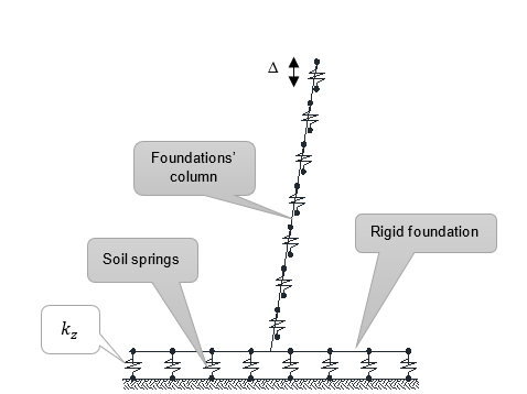
Figure 14-a - Soil springs on column and base of the solid foundation
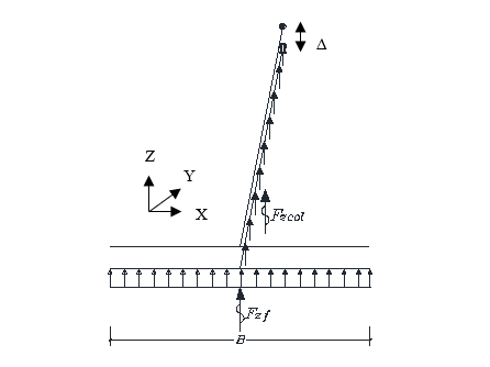
Figure 14-b - Deformed shape of solid foundation and resulted forces
Forces in figure 14-b could be calculated as follows:
(1)
In which, Vi is the volume of the produced rectangular displacement in m3 at the base and projected horizontal column length of the foundation, and kzv is volume stiffness in kN/m3. Then, the total generated force due to the inserted displacement and resulted forces could be calculated as follows:
(2)
On the other hand, the total combined (soil-foundation) vertical stiffness of the rigid foundation and soil is considered equal to soil stiffness (kGazetas); therefore the generated total force is equal:
(3)
In which Δ is initial unit displacement inserted on top node of foundation’s column.
And then the volume spring stiffness (kzv) could be obtained via (4):
(4)
θ is angle of inclination and hcol is height of the foundation’s column. B and L are foundation’s width and length, and d is column width or diameter. Multiplying the resulted kzv from (4) to the contribution area corresponding to each spring of the base and column of the foundation, the nodal soil spring stiffness will be calculated.
Applying the total Force (FTotal) at the top of the foundation’s column in the rigid-foundation model, in which calculated soil springs have been assigned, should produce the initial unit displacement (Δ) that was originally applied. However, inserting total force on the flexible model, in which the calculated values of soil springs have been assigned, creates different displacement and consequently different translational (compression) stiffness of the system. This represents the total stiffness of the soil-flexible-foundation system in vertical displacement in Z axis. The results of soil spring stiffness in kN/m3 for each foundation due to compression displacement in z axis are summarized in Table 10.
Similar to vertical compression direction, the stiffness of soil springs has been calculated through rigid body motion of the solid foundation for horizontal displacements in X and Y directions. Considering soil springs on the edge base and column of the foundation, horizontal forces are produced in foundation and column (Fc and Ff) due to unit displacement of Δ. Figure 15-a represents rigid foundation with soil spring under horizontal displacement (Δ) and figure 15-b demonstrated resulted forces due to such displacement.
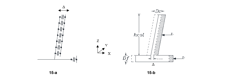
Figure 15 - Rigid body motion of solid foundation in transversal direction
Considering soil spring stiffnesses in X or Y direction (kx or ky) in the rigid foundation equal to soil spring in these directions (kGazetas), kx or ky can be calculated. Resulted soil spring stiffness for each foundation in X and Y translational movement are listed in Table 10.
The results of soil-foundation stiffness for different degrees of freedom of each soil-foundation category will be presented in section 5.1 in the form of complete stiffness matrices.
4.2. Finite Element Modeling and Combined Soil-Foundation Stiffness
Simultaneously using the spring stiffness constants of three translational degree of motions, the finite element numerical models in SAP 2000 have been developed for flexible foundations with their inherent stiffness. As lattice towers transfer mostly translational, and especially vertical forces to the foundation, the calculation of combined soil-foundation stiffness in all degrees of freedom has been performed based on these developed models with merged soil springs in translational movements.
Frame and shell elements have been respectively used to model the base of the grillage and concrete foundations. The column of the foundations are frame elements. According to the meshing dimensions of the shell/frame elements, the soil spring stiffness (values in Table 10) have been assigned to the base and column of the foundations. Figure 16 shows samples of grillage and concrete foundations in three-dimensional presentation in finite element models. The two edges of the foundation have springs in Z and corresponding transversal direction in X or Y direction. The base has springs in Z direction and column nodes have springs in all three directions.
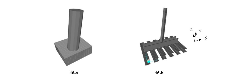
Figure 16-a: Modeling of concrete foundations with shell and frame elements - 16-b: Modeling of grillage foundations by frame elements
Accordingly, unit displacement/rotation has been applied at the top node of the foundation’s column of developed flexible models of the soil-foundation. The top node of the foundation’s column is fixed in all DOFs. The rest of the foundation is free, but soil springs have been assigned to nodal meshing of base and column of the foundation.
| Transversal X | Transversal Y | Compression (Z) | ||
| kx (kN/m3) | ky (kN/m3) | kz (kN/m3) | ||
H2-Grillage | Sand (loose) | 204,882 | 204,882 | 68,895 |
H2-Concrete | 170,654 | 170,654 | 94,923 | |
BSG-Grillage | 204,686 | 207,100 | 25,935 | |
BSG-Concrete | 100,342 | 100,342 | 30,132 | |
H2-Grillage | Sand (compact) | 1,205,037 | 1,205,037 | 585,500 |
H2-Grillage | Clay (compact) | 845,110 | 845,110 | 351,257 |
H2-Grillage | Clay (loose) | 106,691 | 106,691 | 24,681 |
Inserting a displacement or rotation in a specific translation or rotational motion direction could produce extra forces/reactions on other degree of freedom, in addition to direction of insertion, depending on the potential coupled stiffnesses which will be activated on other directions. While the main reactional force/moment is related to the stiffness in that direction, other reactions in other directions, if any, are coupled terms in stiffness matrix.
Figure 17 shows samples of amplified deformed shapes of rigid (on right) and flexible (on left) concrete and grillage foundations against unique displacement at the top point of the column in different directions, which have been modeled with calculated springs in previous section. As the short column of the foundation in lattice towers are inclined, the finite element models of the foundations have been created according to certain angle of inclination. The angle of column is in direction of the tower’s leg and is about 10 degrees for the studied towers.
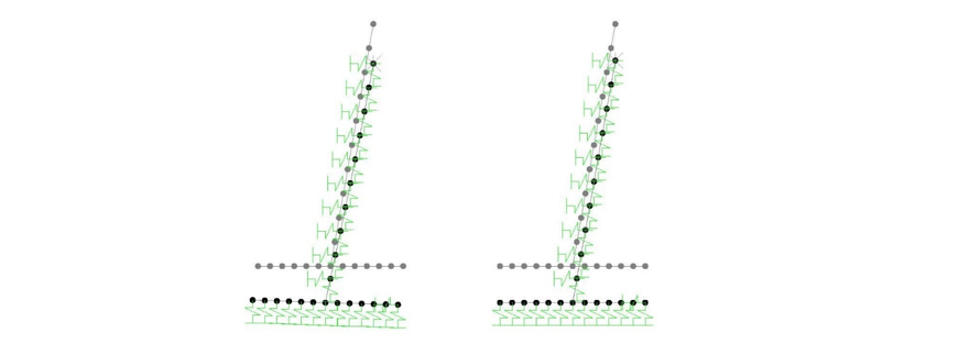
Figure 17-a: Deformation of flexible and rigid concrete foundation due to vertical unique displacement
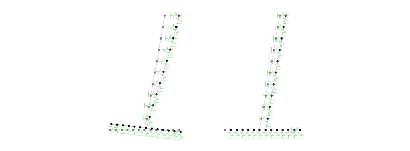
Figure 17-b: Deformation of flexible and rigid concrete foundation due to lateral unique displacement
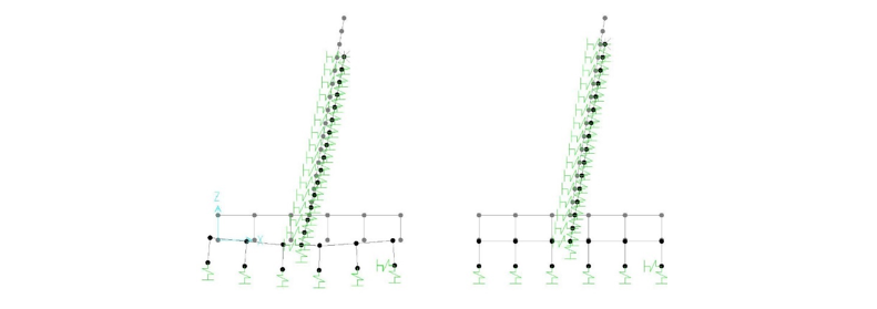
Figure 17-c: Deformation of flexible and rigid grillage foundation due to vertical unique displacement
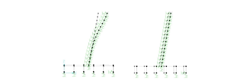
Figure 17-d: Deformation of flexible and rigid grillage foundation due to lateral unique displacement
5. Results and Discussion
5.1. Complete Stiffness Matrices with Coupled Terms
Based on the developed finite element models of flexible and rigid foundations for each degree of freedom, complete stiffness matrices have been calculated. The following results represent complete stiffness matrix of each soil-foundation combination.
To provide comparison between flexible and rigid foundation, for the H2 grillage foundation in loose sand as a sample, both matrices have been presented in Table 11-a and 11-b. For the rest of the foundations only matrices for the flexible foundations are presented in Tables 12 to Table 17. The units in the matrices are based on kN, m and radians. The resulted matrices are symmetrical six by six complete stiffness matrices.

Table 11-a: Complete Stiffness Matrix of Flexible Foundation, H2 Grillage 1.2x1.2x1.8 (compact sand)
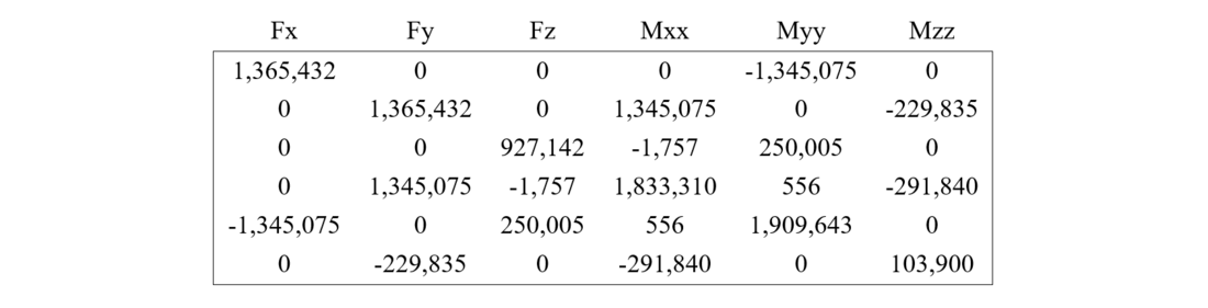
Table 11-b: Complete Stiffness Matrix of Rigid Foundation, H2 Grillage 1.2x1.2x1.8 (compact sand)

Table 12: Complete Stiffness Matrix of Flexible Foundation, BSG Grillage 3.79x3.2x3 (loose sand)
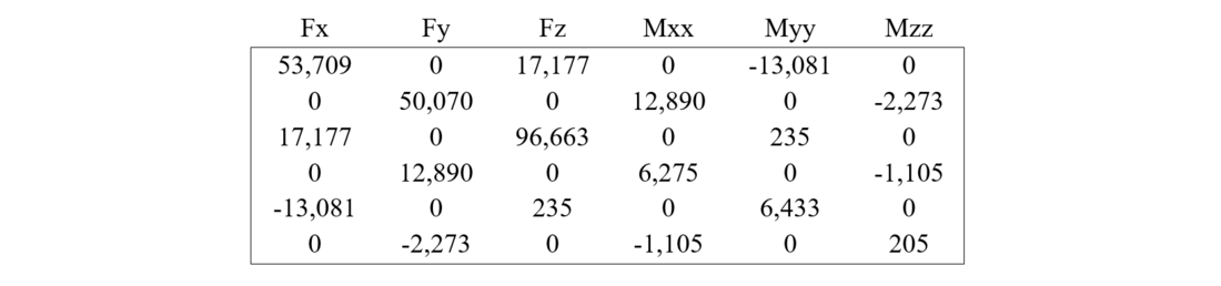
Table 13: Complete Stiffness Matrix of Flexible Foundation, H2 Grillage 1.4x1.4x1.7 (loose sand)
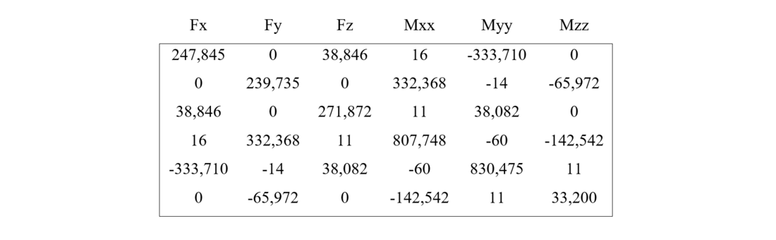
Table 14: Complete Stiffness Matrix of Flexible Foundation, BSG Concrete 3.2x3.2x3.4 (loose sand)

Table 15: Complete Stiffness Matrix of Flexible Foundation, H2 Concrete 1.2x1.2x2.0 (loose sand)
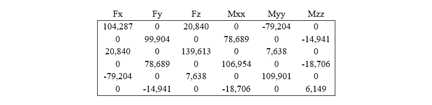
Table 16: Complete Stiffness Matrix of Flexible Foundation, H2 Grillage 1.3x1.3x1.7 ( compact clay)

Table 17: Complete Stiffness Matrix of Flexible Foundation, H2 Grillage 1.8x1.8x1.8 (loose clay)
The developed stiffness matrix of each soil-foundation system could be applied in numerical modeling of the complete tower to consider the flexibility/rigidity effects of soil, foundation (depending on the foundation type) and their interaction. The resulted matrices show that the combined stiffness is very dependent on the soil, and foundation type. There is also noticeable difference between stiffness matrix of rigid-foundation-soil and flexible-foundation-soil systems. As the stiffness in Z direction of the developed matrices is based on compression rigid body motion, the Z stiffness should be modified based on the developed normalized curves for uplift legs.
Table 18 presents the ratio of the dominant total stiffness of flexible foundation (ktotal, combined stiffness of soil-foundation system) to soil stiffness (ksoil) in different translation directions of different foundation-soil types. Generally, the ratios are highly dependent on the foundation types and dimensions. The ratios show that foundation flexibility in each soil-foundation case has greater effect in translational X and Y directions, comparing to Z direction. Besides, the ratios in X and Y directions are almost equal and the minor differences are due to the differences between width and length of foundations.
ktotal/ksoil | ||||
| X | Y | Z | ||
Sand (compact) | H2-Grillage | 0.16 | 0.15 | 0.30 |
Sand (loose) | BSG-Grillage | 0.20 | 0.23 | 0.42 |
BSG-Concrete | 0.51 | 0.49 | 0.83 | |
H2-Grillage | 0.28 | 0.26 | 0.67 | |
H2-Concrete | 0.41 | 0.40 | 0.91 | |
Clay compact | H2-Grillage | 0.16 | 0.16 | 0.37 |
Clay loose | H2-Grillage | 0.28 | 0.26 | 0.71 |
5.2. Evaluation of Soil-foundation Flexibility Effects
To evaluate effects of studied soil and foundation types and their individual and combined stiffness on the tower case studies, the developed stiffness matrices are used along with the foundations’ design loads for each tower. As the connection of the towers’ leg to the foundation is considered pinned, no moment is affected to the stiffness matrix. The results are presented in the form of produced displacements.
Figure 18 shows vertical displacement, due to the applied translational designed force, of grillage foundation (flexible and rigid) in different soil types for H2 tower. The applied forces include a major vertical compression force equal to 220 kN along with longitudinal and transversal forces of 7.2 and 7.0 kN. In the following figure H2-G means H2 tower with grillage foundation; the numbers after it represent length, width and depth of the foundation.
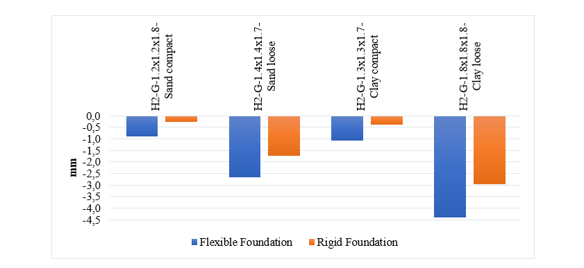
Figure 18 - Vertical displacement due to designed forces on different grillage foundations of H2 tower
Generally, as could be seen in Figure 18, the displacement of the system (soil-foundation) is greater when the soil condition is loose, even if the dimension of the foundation is larger than those of compact ones. In addition, comparing displacement of rigid and flexible foundation in each soil type, results show that in case of compacted soils the effect of grillage foundation flexibility is considerably more important in total combined stiffness of the system. That is, the displacement of flexible foundations is equal to 3.32 and 2.71 times the ones of the rigid foundations, respectively in case of compacted sand and compacted clay. Meanwhile, for loose sand and loose clay soil conditions the ratios are 1.54 and 1.49. The highest displacement is for flexible foundation in clay loose and minimum displacement is for rigid foundation in sand compact condition. It should be noted that the grillage foundation’s flexibility might be underestimated in the present study due to joints and bolt slippage in connection of its members, which have not been considered in numerical modeling. Therefore, this would further increase the importance of the flexibility of these foundations’ type in combination with different soil types, especially dense soils.
In the case of concrete foundation for H2 tower (namely H2-C in the following figure), the vertical displacement has been compared to grillage foundation for both flexible and rigid types of each of them in the same soil types. Left bars in Figure 19 represent flexible and rigid grillage foundation displacement, whereas right bars are related to flexible and rigid concrete foundations. The results show that in the case of concrete foundation, the flexibility of the foundation has less effect in total stiffness of soil-foundation, in comparison to grillage foundation.
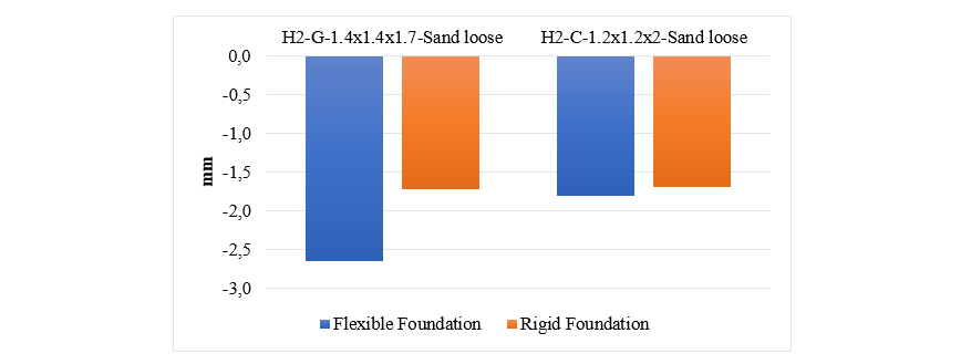
Figure 19 - Vertical displacement due to designed forces on grillage and concrete foundations of H2 tower
Similar to H2 tower, the designed compression and horizontal forces on the BSG tower’s foundation have been assigned to the developed stiffness matrices. The major component of applied force is in vertical compression in Z direction with a value of 1141 kN. Longitudinal and transversal force components are equal to 18 and 22 kN. Figure 20 presents the resulting vertical displacement of the soil-foundation system for both rigid and flexible foundations of grillage and concrete types. The left bars show flexible and rigid grillage foundations, while the right bars show flexible and rigid concrete foundations. Results demonstrate that the displacement difference between flexible and rigid concrete foundation is not so significant, comparing to that of rigid and flexible grillage foundations.
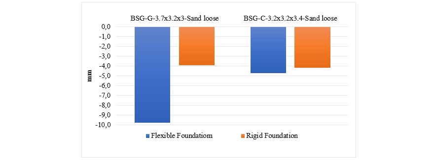
Figure 20 - Vertical displacement due to designed forces on grillage and concrete foundations of BSG tower
For the grillage foundation, the displacement of the soil-flexible foundation is 2.49 times of the soil-rigid foundation system; however, this ratio for concrete foundation is about 1.13. Therefore, as the grillage foundation is itself less stiff than concrete foundation, the effect of foundation flexibility has significantly more impact on combined stiffness of the system. This effect, as was discussed for H2 tower foundations, is more noticeable when the grillage foundation is accompanied with a compact soil type.
6. Summary and Conclusion
Seven different grillage and concrete foundations were designed in different soil type conditions for two specific lattice towers, namely H2 and BSG, which are commonly used by industrial partners. To predict uplift stiffness of the soil-foundations’ system, existing experimental pullout tests were analyzed and three-linear normalized curves were developed for different soil and foundation types. The normalized curves demonstrate respectively elastic, transition state and plastic behavioral phases of soil-foundation system under uplift forces. Differences in developed normalized curves express that the stiffness value is highly dependent on the soil and foundation type. Further experimental pullout tests on the two types of foundations in each soil type with different level of resistance and compaction are needed to provide more insight and generality for the presented normalized curves.
To predict the stiffness of the soil-foundation system in other degree of freedom, stiffness functions of Gazetas [18] have been simultaneously used with developed rigid body motion and finite element method to evaluate the combined soil-foundation stiffness.
Finally, the suggested method resulted in a complete six by six symmetrical stiffness matrix, for which the coupled terms have also been calculated in addition to diagonal terms. As the foundation’s column is inclined, additional coupled terms are generated in the stiffness matrix.
The developed stiffness matrices could be applied in numerical modeling of the tower. The general investigation of the resulting displacement based on the calculated stiffness matrices for different soil and foundation type show that the stiffness of the combined system of the soil-foundation depends on various parameters such as foundation type (grillage or concrete) and characteristics including dimensions and thickness and column stiffness, soil types and properties and its level of resistance. Therefore, it is needed to investigate each soil-foundation case separately and it would be debatable to provide general rule even for a specific soil-foundation type.
Results also demonstrate that grillage foundations flexibility could reduce the combined stiffness of the system more considerably than for concrete foundations. In addition, when grillage foundation is laid on compacted soil types, the flexibility of the foundation has more effect on total stiffness of the system, in comparison to loose soil situation. For example, as discussed and illustrated in Figure 18, applying flexible grillage foundation for H2 tower could increase the resulted displacement about 3.32 and 2.71 times the ones of rigid foundations, respectively in compacted sand and compacted clay soil condition. Utilization of grillage foundation on loose sand for BSG tower could produce the smallest rigidity of the system, which the resulted displacement could be increased until 2.49 times when the flexibility of the foundation has come into account. Similar observations are made for the H2 tower and difference between flexible and rigid displacement is in the order of 1.54 times.
As a whole, the results show that consideration of foundation and soil flexibility and also the way in which they are combined and interact could change the results noticeably and therefore is needed to be considered in realistic numerical modeling and study of the complete structure. The effects of foundation flexibility are more noticeable for grillage foundations and especially when they are used in compact soil sites. To have more insight on the suggested numerical method, experimental tests results of the prototype cases of designed foundations could be compared to the results of theoretical methodology of this paper.
Acknowledgements
The authors would like to acknowledge the financial support of Hydro-Québec, RTE (France), Rio Tinto, NSERC, and InnovÉÉ. They also express their gratitude to Hydro-Québec and RTE for providing foundation test results data.
References
- Savory, E., Parke, G.A.R., Disney P., Toy, N. 2008. Wind-induced transmission tower foundation loads: a field study-design code comparison. Journal of Wind Engineering and Industrial Aerodynamics, 96 (8): 1103–1110.
- Shu, Q., Huang, Z., Yuan, G., Ma, W., Ye, Sh., Zhou, J. 2018. Impact of wind loads on the resistance capacity of the transmission tower subjected to ground surface deformations. Thin-walled Structures. 131. 619-630.
- Jendoubi A. 2015. Effet de l'interaction dynamique linéaire et non-linéaire sol-structure: application aux pylônes de transport d'énergie. PhD thesis. Université de Sherbrooke. Québec. Canada.
- CIGRE. 2020. Conseil International des Grands Réseaux Électriques, B2. Dynamic loading effects on overhead lines: Impacts on foundations. CIGRE B2, Overhead lines, Reference 788.
- Gani, F., Legeron, F., Ashby, M., (2009). Dynamic Wind Analyses of Transmission Line Structures, ASCE Electrical Transmission and Substation Structures Conference. 423-434.
- Asgarian B., Dadras Eslamlou S., E.Zaghi A., Mehr M. 2016. Progressive collapse analysis of power transmisson towers . Journal of Construction Steel Research. 123. 31-40.
- Kyung, D., Choi, Y., Jeong S., Lee J. 2015. Improved performance of electrical transmission tower structure using connected foundation in soft ground. Energies. 8. 4963-4982.
- Roesset, J. M. 1980. A review of soil-structure interaction, Soil-structure interaction: The status of current analysis methods and research. J.J. Johnson. Report US. Regulatory Commission and Lawrence Livermore Laboratory.
- V. Anand. and S. R. Kumar 2018. Seismic Soil-structure Interaction: A State-of-the-Art Review. Structures. 16. 317–326.
- CIGRE. 2019. Conseil International des Grands Réseaux Électriques, B2.24. Dynamic loading effects on overhead lines: Impacts on structures, CIGRE Technical Brochure 809.
- Dutta S. Ch. and Roy R. 2002. A critical review on idealization and modeling for interaction among soil–foundation–structure system. Computers and Structures. 80. 1579–1594.
- Ye, M., Chen H., Zhao X., Huang Y., 2016. Bolt Joint Effects on the Ultimate Bearing Capacity of a Lattice Transmission Tower with Non-uniform Settlement, 2nd International Conference on Sustainable Energy and Environmental Engineering.
- Langlois S., Prud’homme S., Légeron F., Pourshargh F., 2016. Review of advanced modelling methods for lattice steel towers, 2016 CIGRE-IEC Colloquium, Montréal, QC, Canada.
- Sad Saoud K., Langlois S., Bouchard P. L., Lamarche Ch.Ph., 2021. A numerical procedure for the analysis of the buckling and post-buckling behavior of steel lattice towers in overhead transmission lines. CIGRE Science and Engineering.
- Gazetas, G and Apostolou, M, 2004. Nonlinear soil-structure interaction: Foundation uplifting and soil Yielding, Proceeding third UJNR workshop on soil-structure interaction Marc 29-30, 2004 Menlo Park, California, USA.
- Roesset, J. M. 1980. A review of soil-structure interaction, Soil-structure interaction: The status of current analysis methods and research. J.J. Johnson. Report US. Regulatory Commission and Lawrence Livermore Laboratory.
- Pais, A. and Kausel, E. 1988. Approximate formulas for dynamic stiffnesses of rigid foundations. Journal of Soil Dynamics and Earthquake Engineering. 7 (4). 213-227.
- Gazetas, G. 1991. Formulas and charts for impedances of surface and embedded foundations. Journal of geotechnical engineering. 117(9). 1363-1381.
- Mylonakis, G., Nikolaou, S., and Gazetas, G. 2006. Footings under seismic loading: Analysis and design issues with emphasis on bridge foundations. Journal of Soil Dynamics and Earthquake Engineering. 26. 824-853.
- Gazetas, G., Anastasopoulos, I., Adamidis, O., & Kontoroupi, T. 2013. Nonlinear rocking stiffness of foundations. Soil Dynamics and Earthquake Engineering. 47. 83‑91.
- Bowels, J. E. 1997, Foundation Analysis and Design, Fifth edition, International Eddition. The McGraw-Hill Companies, Inc.
- EPRI. 1990. Manual on Estimating Soil Properties for Foundation Design. Electric Power Res. Inst. EL-6800. Research Project 1493-6.
- Anbazhagan, P., Parihar A., Rashmi H.N. 2012, Review of correlations between SPT N and shear modulus: A new correlation applicable to any region. Soil Dynamics and Earthquake Engineering. 36. 52‑69.
- Hydro-Québec 2012, Conception des fondations des pylônes à treillis de type rigide. Spécification technique normalisée, SN-41.6.
- E.D.F. 1992, Essai d’arrachement sur massif superficiels et analyse des méthodes de calcul géotechniques. Plan de Classement GEDOC N◦ 62.02.010, Electricité de Francs (E.D.F.)
- EPRI. 1995. Reliability-Based Design of Foundations of Foundations for Transmission Line Structures. Electric Power Res. Inst. TR-105000. Research Project 1493-04.
- EPRI. 1983. Transmission line structure foundations for uplift-compression loading. Electric Power Res. Inst. EL-2870. Research Project 1493-1.
- Terzaghi, K., 1943. Theoretical Soil Mechanics, JohnWiley and Sons, New York, NY, USA.
- NIST., National Institute of Standards and Technology, (2012). Soil-structure interaction for building structures. NIST GCR 12-917-21. Maryland: NEHRP Consultants Joint Venture.
- Hydro-Québec. 2005. Amélioration de la Robustess des Lignes de Tarnsport. Résistance en Soulèvement des Fondations Existence de Type Grillage. LCG-39.DOC-18.
- Kulhawy, F.H. and Stewart, H.E. 1994. Uplift Load-Displacement Behaviour of Grillage Foundations. Foundation and Embankment Deformations. 233-244.
- Bahari M., Langlois S., Prud’homme S., 2022. Assessment of Pullout Stiffness of Grillage Foundations in Lattice Tower Structures. CSCE 2022 Annual Conference. BC. Canada.
- Kulhawy, F.H., 1988. Tension Behavior of Foundations in soil, an overview. Cross Canada Lecture.
- Kulhawy, F.H., Stewart H.E., Trautmann C.H. 2003. On the Uplift Behaviour of Spread Foundations. Fondations superficielles. Magnan et Droniuc. Presses de l’ENPC/LCPC, Paris. 327-334.
Appendix. Calculation of Theoretical Stiffness of Foundation based on the Gazetas’ Equations
Theoretical relations which have been employed to calculate foundation stiffness according to the Gazetas’ equations in six degrees of freedom are as follows. Surface stiffness is the stiffness of the foundation without consideration of embedment.
(1-1)
(1-2)
(1-3)
(1-4)
(1-5)
(1-6)
In which, B and L are respectively half of foundation’s width and length. Ix, Iy, and Iz are respectively moment of inertia of the foundation in X, Y, and Z directions.
The η factor which is affected to the surface stiffnesses to consider the embedment depth of foundation for each direction is as follows:
(1-7)
(1-8)
(1.9)
(1-10)
(1-11)
In which:
(1-12)
(1-13)
(1-14)
(1-15)
(1-16)
Ab and Aw are respectively surface foundation area and sidewall-solid contact area. D, d, and h are respectively depth of embedment, height of effective side wall contact, and depth to the centroid of effective sidewall contact.
The calculation is presented for a sample soil-foundation: H2-grillage foundation in loose sand. The soil characteristics for sand soil (loose) is as defined in Table 1. Geometrical characteristics of the foundation is summarized in Table 1-1.
| 2L (m) | 2B (m) | L (m) | B (m) | Ab (m2) | χ |
|---|---|---|---|---|---|
1.40 | 1.40 | 0.7 | 0.7 | 1.96 | 1 |
In the following, the results of calculation of the soil theoretical stiffness based on the equations 1-1 to 1-16 are presented. Tables 1-2 and 1-3 show respectively translational stiffnesses in X, Y, and Z directions. Tables 1-4 to 1-6 summarize the soil stiffness parameters in rotational X, Y, and Z (kt: torsional stiffness) directions.
| ky (kN/m) | h=zw (m) | ky,Emb (kN/m) | kx (kN/m) | kx,Emb (kN/m) | |
|---|---|---|---|---|---|
92,474 | 1.625 | 2.348486 | 217,175 | 92,474 | 217,175 |
| kz (kN/m) | D (m) | d (m) | P (m) | AW (m2) | kz,emb (kN/m) |
|---|---|---|---|---|---|
102,182 | 1.7 | 0.15 | 5.6 | 0.84 | 144,067 |
| Ibx (m4) | kxx (kN/m) | krx-emb (kN/m) | |
|---|---|---|---|
0.3 | 41,052 | 1.551238 | 63,682 |
Iby | kyy | kry-emb | |
|---|---|---|---|
0.3 | 41,052 | 1.551238 | 63,682 |
Ibz | kt | js | jr | Γw | Γrt | kt-emb | |
|---|---|---|---|---|---|---|---|
0.6 | 82,325 | 0.55 | 0.6 | 1.677769 | 1.480982 | 2.484746 | 204,556 |