Repurposing coal power station generators as synchronous condensers on the South African grid
Authors
M. TOMLINSON, F. JOOSTE, U. MINNAAR, W. FARMER
Research Testing and Development, Eskom Holdings SOC Ltd, Cape Town, South Africa

Summary
South Africa’s electricity supply industry is undergoing several reforms simultaneously, affecting both the industry’s structure and the country’s energy mix. These changes include significant growth in inverter-based generation resources such as solar PV and wind as well as the planned shutdown of the majority of South Africa’s coal fleet over the next two decades. This will result in a reduction in the amount of synchronous generation on the South African grid along with the grid services these generators provides. This paper investigates the technical, operational, and regulatory considerations for converting synchronous generators to synchronous condensers to provide grid services to the South African electricity grid.
Keywords
Synchronous condenser conversion, Repurposing, Coal-fired power station decommissioning1. Introduction
This paper investigates the technical, operational, and regulatory considerations for possibly converting synchronous generators to synchronous condensers to provide grid services to the South African electricity grid.
South Africa’s electricity supply industry is undergoing several reforms simultaneously, affecting both the industry’s structure and the country’s energy mix.
Lowering costs for renewable energy generation, more specifically, solar photovoltaic (PV) and wind, has led to these being the lowest-cost source of electricity generation. This development has led to the uptake of solar PV and wind internationally. South Africa has followed this trend, and the Integrated Resource Plan shows an expansion for renewable energy generation on the grid.
Alongside this increasing role for renewable generation, many of Eskom's coal generation power stations are reaching the end of their design life and will soon be retired. This development affects the operation of the power system, particularly the provision of services required for reliability (adequate reserve, voltage, and frequency) by synchronous generators. While solar PV and wind provide cheap energy, these generation sources are primarily connected to the grid via inverters and have significant limitations as they do not supply the same technical resources like voltage and frequency management, nor are they dispatchable.
The other significant change happening is the reform of the power sector. Eskom is moving from a vertically integrated utility to three separate independent divisions. The transmission division was the first to be unbundled and is responsible for grid operations, the energy market and other services required for a reliable and adequate electricity supply.
1.1. Integrated resource plan
The Integrated Resource Plan (IRP), developed by the South African national government Department of Mineral Resources and Energy (DMRE), determine the future energy mix of South Africa’s electricity generation. The IRP aims to provide the optimal energy mix for South Africa based on energy and policy needs. The official version at the time of writing is the 2019 revision (IRP-2019). A draft revision (IRP-2023) has been published for comment, but for the purpose of this paper, the current approved IRP-2019 is considered. Figure 1.1 illustrates a snapshot of the energy mix that is the outcome of the IRP-2019 modelling exercise.
Figure 1.1 [1] illustrates several noteworthy characteristics of South Africa’s energy mix projected over the decade up to 2030:
- There will be a significant addition of new renewable generation - both wind and solar PV.
- The IRP allocates 500 MW per annum for distributed generation, which is in addition to the existing growth in distributed generation in South Africa.
- There are significant decommissioning plans for Eskom’s coal fleet.
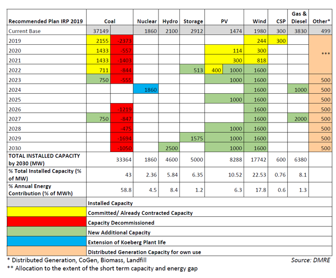
Figure 1.1 - Energy mix from IRP-2019
With South Africa’s loadshedding having worsened significantly during 2022 and 2023, the South African government has responded by taking several measures in response. These include the establishment of a National Energy Crisis Committee (NECOM) as well as the relaxation of regulations relating to licensing new generation. Licensing limits were first raised to 100 MW and subsequently, the requirement for a license was removed. This has led to an influx of new project registrations as well as a claimed pipeline of ~10 000 MW of new projects. Over and above this, Eskom has estimated that ~5000 MW of small-scale embedded generation (mainly solar PV) will be connected to the South African grid by the end of 2023, up from ~1000 MW in 2022. This rapid acceleration in solar PV uptake is expected to continue into the foreseeable future. The future generation profile will look significantly different from that laid out in IRP-2019, with the generation shortfall playing a key role in renewable generation uptake increasing significantly from the expected levels when IRP-2019 was drafted.
1.2. Coal decommissioning
Over the next three decades, Eskom’s coal fleet plants will sequentially reach the end of their design life and be decommissioned. Figure 1.2 illustrates the timeline for decommissioning the coal fleet.

Figure 1.2 - Coal fleet decommissioning [2]
Figure 1.2 shows that by 2050 the coal fleet will be systematically decommissioned with only the Medupi and Kusile being active beyond 2050. The decommissioning of the coal fleet has broader implications for South Africa’s electricity grid beyond the energy generated by these plants.
Synchronous generators as found in coal, nuclear and gas power stations provide a range of services to the grid (and customers) above and beyond the megawatts and megawatt-hours on their nameplates, without which the grid would not be able to operate. These include:
- Short circuit power.
- Providing true inertia.
- Providing instantaneous mechanical responses to disturbances.
- Provide reactive power compensation.
- Provide dynamic MVARs that increase voltage stability.
- Contributes to reference voltage sinus wave for grid-following inverters.
Most of these services can either not be provided by inverter-based generation sources such as solar and wind generation or can only be partially fulfilled by them. The net effect of the increasing contribution of inverter-based generation and the decommissioning of the coal fleet is that the South African power system will see a reduction in the grid and reliability services needed to operate the grid safely and reliably.
1.3. Impact on system inertia and frequency stability
With the strong coupling between a synchronous machine's mechanical and electrical dynamics, the rotating mass provides inertia to the electrical frequency. The electromagnetic and inertial response is automatic and instantaneous to stabilise the system frequency after a generation/load imbalance disturbance. Inertia is the primary source for frequency transient stability, a service that is currently provided for free by synchronous machines in South Africa.
A reduction in rotational inertia increases the sensitivity of the network frequency. A considerable frequency deviation can lead to the disconnection of generation plants and network components, resulting in cascading trips and, in the worst case, leading to a system-wide blackout.
IRP-2019 shows that there will be significant decommissioning of the coal fleet (synchronous generators) and considerable integration of inverter-based renewable generation (wind and solar photovoltaic). A consequence of this transition is a decline in total system inertia. A decline in system inertia results in a reduction in the power system's frequency transient stability.
Figure 1.3 illustrates the total inertia profile for the Eskom network and how it will evolve. The plot shows the kinetic energy available for an inertial response from each coal power station (synchronous generators) over the decommissioning timeline up to 2050. The graph also includes the kinetic energy aggregate contribution of other synchronous generator-based generations. The red-dotted line illustrates the total inertia constant (normalised with the unit in seconds) based on the IRP-2019 plan up to 2030. The white-dotted line depicts the inertia constant from 2030 to 2050 based on the CSIR's generation capacity prediction (least-cost scenario) [3]. The graph shows that the installed inertia reduces as larger and larger coal-fired power plants are decommissioned. Total installed inertia on South Africa’s grid is expected to halve by 2050 due to the decommissioning of coal-fired power stations. The inertia constant highlights that the growth in generation capacity, due to the increase in inverter-based renewable energy integration, further reduces the power system's overall inertia relative to the system size.

Figure 1.3 - Future installed inertia based on IRP-2019 [1] and CSIR predicted least-cost scenario [3] schedule
The inertia profile in Figure 1.3 is an aggregation of all the synchronous generators in the network, predominantly concentrated in the northern part of South Africa. The total inertia profile ignores the network's spatial element. The frequency response depends on the inertia, the imbalance disturbance's characteristics (magnitude, duration, and location), impedances, and network topology [4]. It is necessary, in practice, to look beyond total inertia and consider the spatial element (distribution) of inertia to improve the network's overall frequency transient stability and response [5].
2. South Africa’s Power sector structure
2.1. The existing Power System Structure in South africa
South Africa’s electricity sector has historically been dominated by Eskom as a vertically integrated utility. Alongside Eskom, electricity distribution is also carried out by municipalities across the country.
“The South African electricity sector is a single-buyer model with Independent Power Producers (IPPs) being contracted by a vertically integrated, state-owned utility complemented by municipal distributors. There is no wholesale (or retail) competition in the supply of electricity” [6].
The electricity structure in South Africa has a largely vertically integrated structure with the national utility, Eskom, responsible for the bulk of electricity generation, alongside IPPs as well as owning and operating the transmission network. Distribution is split between Eskom and municipalities (redistributors) with Eskom supplying ~50% of distribution customers in the country [7].

Figure 2.1 - Structure of the South African electricity sector [8]
Figure 2.1 illustrates the existing structure of the South African electricity sector, including Eskom’s vertically integrated structure.
2.2. Power sector reform
In 2019, the South African president announced the unbundling of Eskom and this has kick-started power sector reform in the country. Following this, the Department of Public Enterprises released a roadmap for the restructuring of Eskom in 2019 [9], which outlines the unbundling and legal separation of Eskom as a vertically integrated utility as well as articulating a number of policy statements regarding the Electricity Supply Industry in South Africa.
The drivers for change identified by the Department of Public Enterprises (DPE) are [9]:
- “The transition from the existing dependence on fossil fuels to the mix of electricity energy sources is reflected in the IRP-2019.
- The restructuring of Eskom into Eskom Holdings with three new subsidiaries: Generation, Transmission and Distribution.
- An intensive focus on radically improving the current operations and eliminating inefficiencies in generation.
- A greater requirement for transparency in the governance of both Eskom Holdings and the subsidiaries.
- A rigorous approach to cutting wasteful costs, optimising revenue and resolving the debt burden; and
- A Just Transition involving all stakeholders to ensure sustainable livelihoods for workers and communities”.
The revised industry structure outlined by the DPE has the creation of a separate Transmission Entity (TE) as its cornerstone reform for the Electricity Supply Industry (ESI).
2.3. Independent transmission system operator
The TE is envisioned to “act as an unbiased electricity market broker, to promote capital investment within the industry and to catalyse energy efficiency and cost sustainability.” [9]
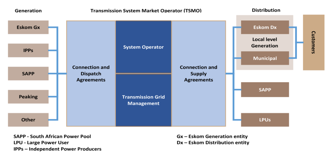
Figure 2.2 - Revised South African electricity industry structure [9]
Key aspects identified by the DPE include that the TE will [9]:
- be a wholly owned Eskom subsidiary and be fully regulated,
- balance electricity supply and demand in real-time,
- dispatch the generators according to least‐cost merit order principles, and
- be empowered to introduce additional markets and products as required e.g., a reserves market.
Figure 2.3 illustrates the phases of Eskom’s legal separation with the creation of three independent legal entities for Generation, Transmission and Distribution, with the Transmission Entity being the first to be legally separated.
The Transmission Entity will be implemented as a Transmission System Operator with four focus areas:
- System Operator - The Transmission System Operator is responsible for the real-time operation of the IPS, including real-time balancing of supply and demand.
- Market Operator - will provide a transparent, non-discriminatory trading platform for market participants allowing willing buyers and sellers to trade with each other on an hourly and daily basis.
- Central Purchasing Agency – will continue the role of the Single Buyer’s Office during the five-year transition to a wholesale market and maintain the role of Buyer for legacy contracts after the transition.
- Transmission Network Service Provider - is responsible for the maintenance and operation of the Transmission grid and coordinating outages with the System Operator.
Figure 2.4 illustrates the four business areas of the Transmission System Operator alongside their functions and level of maturity. The System Operator and Network Services Provider are the mature business areas while the Central Purchasing Agency and Market Operator are the newer business areas to be introduced.

Figure 2.3 - Eskom legal separation process [9]

Figure 2.4 - Transmission system operator
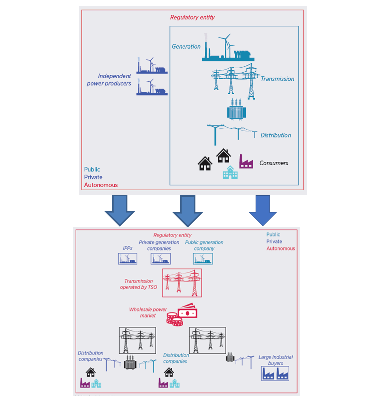
Figure 2.5 - Change in South African power sector structure [10]
Figure 2.5 illustrates the change in the South African power sector from a single buyer market to a wholesale market structure because of Eskom's unbundling into three independent companies. In Eskom’s case, the wholesale power market platforms will be the responsibility of the Market Operator within the newly formed Transmission System Operator. In April 2023, license applications for the new National Transmission Company of South Africa were submitted by Eskom.
2.4. Implications
A key aspect of the wholesale market structure in the revised sector structure is that it effectively means that Eskom Generation is a service provider to the Transmission System Operator (TSO), alongside Independent Power Producers (IPPs) and other private generators and loads that can provide services to either the market platforms or contract for service required by the TSO.
The first implication for Eskom’s generation business is that the business case for any products, such as those provided by a synchronous condenser or ancillary services offering is dependent on the TSO requiring the service and being willing to pay Eskom Generation for that service.
The second implication is that the move away from a vertically integrated structure also implies that the TSO may acquire these services on the open market i.e., Eskom Generation needs to price its services competitively as it no longer has a monopoly in the provision of generation services to the South African grid.
From the perspective of services that Eskom Generation provides via a synchronous condenser, the customer will be the National Transmission Company of South Africa, as the System Operator will be the main procurer of ancillary services, which it buys on behalf of all electricity customers to keep the system in balance.
3. Ancillary services in a South African context
3.1. Overview
With the South African power pool’s declining generation reserve margin and a move to inverter-based generation, the importance of various ancillary services is ever-growing. Ancillary services can be defined as the services procured by the System Operator to maintain a balance in supply (generation) and demand (load) and to operate the power system on a stable and economical basis. Various definitions used internationally for ancillary services are summarised in [11].
Simulations show that by 2030 there could potentially be insufficient inertia to operate the South African power system within acceptable limits due to the increased grid penetration of inverter-based generation resources [12], [13]. The decline in inertia cannot be viewed in isolation and must be considered together with system strength. In South Australia, for example, the Australian Energy Market Operator first declared a system strength shortfall in 2017 before it declared an inertia shortfall in 2018 [14]. This paper therefore only focusses on the ancillary services that support the system through the provision of inertia, dynamic voltage control and short circuit current (which is tied to system strength).
The South African System Operator defines ancillary services, and its subcategories as follows [15]:
- Reserves
- Instantaneous reserve
- Regulating reserve
- 10-minute reserve
- Emergency reserve
- System restoration facilities
- Black Start
- Unit Islanding
- Reactive Power and Voltage Control
- Constrained Generation
These ancillary services can be grouped into three categories namely frequency control (system-wide parameter), voltage control (more a local quantity tightly coupled to the reactive power injection into network nodes) and system restoration.
It is important to note that each of these categories is exclusive, thus, capacity reserved for a particular category may not be used to supplement another [15].
3.2. Reserves
3.2.1. Instantaneous reserves
Instantaneous Reserve is the generating capacity or consumer load contracted to respond to a change in frequency in both directions. The purpose of Instantaneous Reserve is to arrest the frequency within acceptable limits following a contingency, for example, a generator trip or customer load reduction. It must respond fully within 10 seconds and must be sustained for at least 10 minutes.
Although the current version of the South African Grid Code [16] does not explicitly define Fast-Frequency Response (FFR) from inverter-based resources, such as Battery Energy Facilities (BEFs), as a separate ancillary service it is currently treated by the System Operator as instantaneous reserves that is contracted with faster response times than conventional governor-controlled generator units. This may however be revised in the future.
3.2.2. Regulating reserve
Generation capacity or demand side managed load available to start responding to Automatic Generation Control (AGC) instructions within 10 seconds and be fully activated in 10 minutes. The purpose of this is to allow for enough capacity to control the frequency and control area tie-lines power within acceptable limits in real-time.
3.2.3. 10-minute reserve
Generating capacity (synchronised or not) or demand side managed load that can respond within 10 minutes when called upon. The purpose of this reserve is to restore instantaneous reserve and regulation reserve to the required levels after an incident. The Emergency reserve is excluded from the 10-minute reserve.
10-minute reserve is required to balance supply and demand for changes between the day ahead market and real time such as load forecast errors and unit unreliability. The 10-minute reserve is used to restore regulating reserve when required.
3.2.4. Emergency reserves
These reserves are infrequently used. The system operator can use this capacity not only for reserves but also for emergency operation and voltage control. These reserves are normally made up of contracted interruptible load, gas turbines and emergency generation.
3.3. System restoration services
3.3.1. Black start
Black start is defined as the set of actions aimed at bringing the system back to normal operation after a disturbance that caused a blackout or state of emergency. It requires generating units capable of starting up without an external power supply such as pumped storage/hydro units. The pumped storage/hydro facilities certified as black-start facilities are required to have at least two units that can operate in synchronous condenser mode all the time.
This process is carried out sequentially by means of [17]:
- Re-energisation
- Frequency management
- Re-synchronisation
3.3.2. Unit islanding
The requirements for islanding are similar to those of Black Start but the duration is longer. Maintaining generation-demand balance is the primary requirement for stable islanding operation. The generators in the island must be able to maintain the voltage and frequency. In addition, the generators should be able to keep the network impedance within range, the phase symmetry, the ability to handle fault currents, and the resynchronisation with the rest of the network [17].
3.4. Reactive power and voltage control
Reactive power supply and voltage control form part of the ancillary services required by the System Operator to efficiently perform its main function of supplying electrical power within a specific set of defined limits.
Voltage control is achieved by using pumped storage and open cycle gas turbine (OCGT) in synchronous condenser mode, requiring that all generators have automatic voltage regulators (AVRs) in automatic voltage control mode.
The detailed technical requirements for the South African Grid are published annually by the System Operator in the annual Ancillary Services Technical Requirements [15].
3.5. Constrained generation
The South African Grid Code [16] requires that the System Operator manage real-time system constraints within safe operating limits, using constrained generation as one of the ancillary services as required. It requires multiple outages of a credible nature to be studied to ensure that the operation of the system protects against cascading outages for such an event, wherever practical.
4. Technologies providing inertia, dynamic voltage control and system strength
4.1. Overview
The ancillary services that support the system through the provision of inertia, dynamic voltage control and short circuit current are controlled by means of the following:
- Frequency control
- Inertial response (Slows the rate of change of frequency)
- FFR from inverter-based generating units (Halts or arrests frequency deviations)
- Governor response from non-inverter-based generating units (Halts or arrests frequency deviations, slower response time than FFR)
- AGC response (Restores frequency to nominal value)
- Voltage control
- Generating units
- Generating units running in synchronous condenser mode
- Other equipment used by the system operator to control voltage (shunt, line reactors, shunt capacitors, Static VAR Compensators (SVC), standalone Synchronous condensers)
- Short circuit current
The available short-circuit current and voltage control are intricately connected. What this implies is that as the short-circuit current in the power system decreases it becomes more difficult to perform voltage control, especially during the switching of reactive devices such as lines and capacitor banks. Peak-short-circuit current is eroded in a system when synchronous-machine-based generator units are decommissioned and replaced by inverter-based generator units that do not provide the same magnitude and speed of response.
Short-circuit current is a requirement to start large motors, energise large transformers and it sensitises the selectivity of protection devices. It also helps to mitigate the effect of inverters and rectifier-based non-linear loads on the power system.
Short-circuit current in a power system is mainly provided by synchronous generators. In a large power system, inverter-based technologies do not contribute significantly to system fault current due to the intrinsic nature of the technology. Inverters cannot surpass their rated current capacity. When overcurrent conditions occur, the inverter will limit the output current or switch off to manage the situation.
4.2. Supplemental inertia devices
4.2.1. Power system inertia and rate of change of frequency (RoCoF)
During a power system disturbance, such as the sudden loss of generation units or a large increase or decrease of load, the total system inertia determines the initial Rate of Change of Frequency (RoCoF). The frequency response is described by the following equation, assuming that load damping is zero [18]:
(4.1)
Where:
ΔP = Size of contingency (MW lost)
H = System inertia (MW seconds)
f0 = Frequency at the time of disturbance (Hz)
= Rate of Change of Frequency (Hz per second)
From (4.1) it is shown that the initial RoCoF is only influenced by the contingency size and the available online system inertia.
During such events, synchronous generators provide an inertial response by instantaneously absorbing or releasing kinetic energy to and from their rotational mass. This allows slower reacting resources time to respond and arrest frequency change [19], [20].
From (4.1) it is further shown that the RoCoF will increase as the system inertia decreases for any given contingency size. Without sufficient inertia, a power system will struggle to ride through large frequency disturbances as synchronous generators (hydro, steam and gas turbines) find it difficult to remain synchronised with a RoCoF above 2 Hz/s [21].
The frequency-control diagram in Figure 4.1 depicts a typical response following a system disturbance. In the illustrative depiction, the disturbance occurs when the frequency is close to the target frequency of 50 Hz. Power system control schemes generally implement a frequency control dead-band to avoid hunting between the generators when the frequency is close to the target. In this case, the lower dead-band threshold is 49.85 Hz.
When the frequency is within the control dead-band, the inertia provided by the synchronous generators is the only factor that limits the RoCoF. The control response is only activated when the frequency crosses below the 49.85 Hz threshold.
The first part of the primary control response can be obtained from inverter-based instantaneous reserves, such as battery energy storage systems, that can provide FFR. At least 200 ms to 400 ms is required for the inverter’s controller to reliably measure and detect the sudden decline in frequency. Only after this initial delay does the inverter respond according to its frequency-droop-control setting.
The second part of the primary control response can be obtained from the traditional, slower responding, instantaneous reserve. These are generator units on governor control, such a gas-turbines, hydro and coal-fired units. They are required to respond within one second, be fully activated within 10 seconds and be sustained for 10 minutes.
The secondary response follows with the activation of the regulating reserves. This is provided by units that are on AGC. The South African Grid Code requires that these reserves activate in 10 seconds, be fully activated in 10 minutes, and be sustained for one hour [16].
The tertiary response follows with the activation of the 10-minute reserve and possibly emergency reserve, sustained for up to two hours. Thereafter supplemental reserve may be called up.

Figure 4.1 - Frequency-control diagram following a large disturbance in the power system (depicted)
When considering the role of inertia in this context, it is important to draw a distinction between inertia, where the active power that is injected or absorbed is proportional to the change in frequency (df / dt), as opposed to instantaneous reserve, where the active power is proportional to the frequency-droop-control settings. Although both ultimately affect the RoCoF and serve to arrest the decline in frequency, the dynamic behaviour and speed of response are different.
4.2.2. Synthetic and virtual inertia
The FFR from grid-following inverters is commonly referred to in literature as synthetic inertia while the active power injection from grid-following inverters is termed emulated or virtual inertia [22], [23]. The definition of FFR and synthetic inertia is often used interchangeably, and definitions differ between regions. This disparity often leads to an incorrect understanding that the FFR from inverter-based resources, operating with frequency-droop control, is a form of synthetic inertia.
Resources on frequency-droop control do form part of the frequency-control response, as depicted in Figure 4.1, but the response is proportional to frequency and does not exhibit the dynamic behaviour of inertia. This should be clearly distinguished from control strategies that emulate inertia [24], [25], [26] by responding to df / dt.
The British Grid Code [27], as an example, defines “Active RoCoF Response Power” as “the Active Inertia Power developed from a Grid Forming Plant plus the Active Frequency Response Power that can be supplied by a Grid Forming Plant when subject to a rate of change of the System Frequency”. This appears to suggest that the Active RoCoF Response Power only responds to df / dt. However, Active Frequency Response Power is separately defined as the injection or absorption of active power during a deviation of the system frequency away from the target frequency, similar to Primary Response, but with full activation within 1 second. This clarifies that Active RoCoF Response Power may also include resources on frequency-droop control. In this case, the RoCoF response may not only include inertial-response dynamics, but also frequency-droop dynamics.
Countries with high levels of inverter-based generation such as Spain, Denmark and Ireland now require various types of active power control measures to be included in their wind plants. These measures include emulation of inertial frequency response and power reference tracking which must assist in the regulation of grid frequency.
In wind turbines, this can be achieved by temporarily slowing the turbine during which stored kinetic energy in the rotor can be extracted to emulate synchronous generator inertial response. This process is not limited to wind turbines but other inverter-based generation technologies such as solar PV and batteries have the same capability with the correct implemented control systems [28]. However, it must be noted that currently this emulated inertial response can only be used for primary frequency regulation and not in the true sense of instantaneous inertial response.
The literature demonstrates that if inverter-based generation penetration is below 20% the synthetic inertia developed by these devices can be used to reduce the RoCoF and minimum frequency nadir in conjunction with the synchronous generators [29], [30], [31]. However, there are some drawbacks, especially in the case of wind inertial response where it may result in a significant slowdown of frequency recovery and a potential second frequency nadir. A list of supplemental synthetic inertia devices which could be utilised for primary frequency regulation is given in Table 4.1.
Supplemental device/mechanism | Type of inertia | Additional notes | |
|---|---|---|---|
| Synchronous | Synthetic | |
Synchronous compensators (condensers) | X |
| New or retrofit generators synchronised with the power system normally used for voltage control and reactive power support i.e., generators operating in synchronous condenser mode. |
Rotating stabilisers | X |
| Synchronous machine designed with a high mass. |
Wind turbines | X |
| Synchronous provision of inertia if directly coupled (no inverter interface). |
Pumped hydro | X |
| Synchronous machine online for inertia provision. |
Compressed Air Energy Storage | X |
| Operates like a normal gas turbine power plant by providing inertia, primary, secondary, and tertiary response. |
“Parking” | X |
| Operating generation plant at low MW output (no provision of other system services). |
Reduction of unit/power station minimum generation | X |
| Keeping more units online by retrofitting for increased flexibility. |
Flexible thermal power plants | X |
| Fast response gas turbines. |
AC interconnectors | X |
| Increased synchronous interconnections of South Africa to the Southern African region (increasing the synchronous area |
Battery technology |
| X | Provide “synthetic” inertia response via inverter interface to the power system with appropriate control loops. |
Flywheels |
| X | High speed machines that provide synthetic inertia for short durations. |
Wind turbines |
| X | Non-synchronous inverter interconnected wind turbines can provide synthetic inertia response for a few seconds with well-defined and tuned control loops. |
HVDC interconnectors |
| X | Provide synthetic inertia response via HVDC links. |
Demand Side Response (DSR) |
| X | Demand reduction in a range of end-user loads (electric vehicle charging/discharging, electric water heating, large industrial loads, data centres, etc.). |
4.3. Devices used for Voltage and reactive power control
There are a variety of devices that can be utilised for the control of voltage and reactive power, these include:
- Capacitor banks
- Conventional generators
- Distributed Energy Resources (DER) with grid-coupling converters
- Inductors
- Reactors
- Synchronous condensers
- Synchronous generators
- Flexible AC Transmission Systems (FACTS) Devices
- FACTS devices with controllers
- Power electronics control devices such as SVC’s
- Static Synchronous Compensators (STATCOMs)
- Unified Power Flow controller (UPFC)
Each of these devices have different specifications and operational characteristics, meaning they are suitable for different use cases and applications.
4.4. System strength and fault current contributing Devices
CIGRE 671 Technical Brochure [33] defines system strength as:
“The change rate in the inverter-based resources terminal voltage relative to its current injection variations.”
In 2017, the Australian Energy Market Commission (AEMC) defined system strength as [34]:
“System strength is a characteristic of an electrical power system that relates to the size of the change in voltage following a fault or disturbance on the power system. System strength can be measured by the availability of the fault current at a given location. High fault levels are generally found in a strong power system while low fault levels are representative of a weak power system. When the system strength is high at a connection point the voltage changes very little for a change in the loading (i.e., a change in load or generation). However, when the system strength is lower the voltage would vary more with the same change in loading.”
In 2018 Australian Energy Market Operator (AEMO) defined system strength in a broader way [35]:
“System strength is an umbrella term that refers to a suite of interrelated factors which together contribute to power system stability. It reflects the sensitivity of power system variables to disturbance, and indicates inherent local system robustness, with respect to properties other than inertia. System strength affects the stability and dynamics of generating systems’ control systems, and the ability of the power system to both remain stable under normal conditions and return to steady-state conditions following a disturbance.”
System strength is proportional to fault level (available short circuit current) at any given point in a power system. Areas closer to synchronous generating units will have higher fault levels than remote areas further away.
Inverter-based generation contributes very little to overall system strength with a fault current contribution of typically 1.1 - 1.5 p.u. [36]. To maintain stability during normal operation, and during contingency events, it in fact, has a minimum system strength requirement [37]. Grid-following inverters follow the grid voltage waveform by locking onto the voltage-phase-angle of the grid and injecting current at an angle relative to the measured voltage waveform (phase-lock loop). After a network-fault event, the inverters must re-lock onto the grid to retain stability. Areas with low system strength will experience larger phase-angle changes between pre- and post-fault conditions compared to stronger systems making it more difficult for the inverters to retain lock onto the system which is required for its stability.
System strength affects the operation of a power system in several ways. The effects of low system strength on a power system include [38]:
- Deeper voltage dips and higher over-voltages.
- Instability of generator / dynamic plant voltage control systems.
- Increases in harmonic distortion (decreased Quality of Supply (QoS) levels).
- Large voltage step changes during switching of reactive power components such as capacitor banks, reactors and lines.
- Lower generator fault ride-through capability.
- Poor protection grading and sensitivity.
- Prolonged voltage recovery after disturbances.
- Voltage and power oscillations across larger areas.
Short-circuit current in a power system is mainly provided by synchronous generators and condensers with typical contributions of 3 to 5 times the generator rating [36]. Inverter-based technologies do not contribute much to system fault current due to the intrinsic nature of the technology (typical fault current contribution of 1.1 to 1.5 times the inverter rating unless it has been explicitly designed for higher values).
4.5. Technology Summary
Table 4.2 comprises a brief comparison of characteristics, advantages, and disadvantages of solutions to inertia shortage, frequency control, voltage control and system strength with a focus on the synchronous condenser.
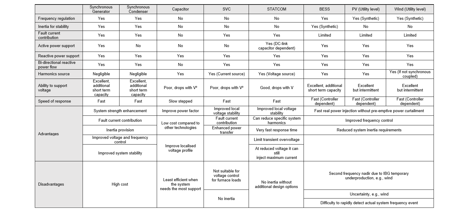
Table 4.2 - Characteristic comparison of solutions to inertia shortage, frequency control, voltage control and system strength [39], [40], [41], [42], [43], [44], [45]
4.6. Ancillary services contributions from different technologies
Table 4.4 lists and categorises ancillary service providers and technologies [46]. The list includes the overarching type of service provided by the ancillary service namely, frequency control, voltage control, system restoration and other.
Table 4.4 also includes information deemed important for the location (L) of the ancillary service provider:
- Provided through the inertial response of the generator.
- While it is not used in Sweden, nuclear power is used in, e.g., France for frequency support.
- This is part of the regulations for production units, it is not monetised.
- Generally, only possible for down-regulation or if it is not producing the maximum available output.
- This is very dependent on the inverter design and rating. Only converters rated for higher capacity to provide continuous reactive support will be able to provide this function.
- It may be possible for an arc furnace to contribute to lower flicker levels based on adjustments to the process.
- More complex to realise since an aggregator might be needed.
Table 4.3 clarifies the colour coding used in Table 4.4.
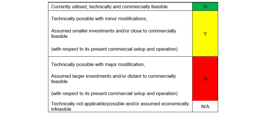
Table 4.3 - The techno-economic categorisation of ancillary services using the following colour code [46]
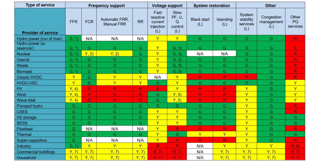
Table 4.4 - Technical and economical categorisation of ancillary services from different types of providers [46]
4.7. Ancillary services offered by synchronous condensers
Synchronous condensers are synchronous machines in which the rotating shaft spins freely with no mechanical load and no turbine driving it. These devices cannot be considered generators or motors driving loads. However, to compensate for losses such as bearing and ventilation losses some active power consumption is necessary.
Synchronous condensers are of interest to the ancillary services market as they store electromagnetic energy and kinetic energy in the rotating shaft assembly to provide inertia during grid disturbances caused by sudden imbalances in system load and generation, thus contributing to lower RoCoF during these events. Additionally, they contribute short circuit current at the point of installation which enables higher levels of inverter-based generation penetration into the existing grid. They are also able to control localised reactive power requirements by means of injecting or absorbing reactive power depending on the value of the excitation current input.
In summary, synchronous condensers have the following benefits:
- Provides inertia (help limit high RoCoF events).
- A source of short circuit current thus increases system strength which in turn contributes to improved protection device grading and helps maintain voltage stability during reactive device switching.
- Provides dynamic voltage control which is step-less and highly responsive voltage regulation with no switching required.
- Provides dynamic reactive power control (fast injection of reactive power to limit voltage drops and fast absorption of reactive power to limit voltage rises).
- Can allow other generators on the network to provide more active power by removing the burden of reactive power support.
- Designed correctly, it has significant overload capability.
- Not a source of harmonics and can be used to absorb harmonic currents.
Considering the above it is evident that synchronous condensers form an integral part of future ancillary service requirements, especially with ever-decreasing system inertia due to the decommissioning of synchronous-machine-based generation and increasing levels of inverter-based technologies, as in the case of the South African power system. Synchronous condensers not only play a role in system frequency stability through the provision of inertia but also voltage stability by means of fault current contribution. Table 4.5 indicates where synchronous condensers can be of value as an ancillary service in the existing South African market (Column 1), in a developed and expanded South African ancillary market (Column 2) and if aligned with some internationally recognised ancillary services (Column 3).
At present, inertia, system strength and dynamic voltage control are not seen as standalone ancillary services by the South African grid code or TSO. However, as synchronous generation is replaced by inverter-based resources, inertia and fault level will become important requirements as the Australian system operator, with higher levels of inverter-based generation on their system, has shown [35], [38].

Table 4.5 - Possible synchronous condenser applications (indicated by *) in the existing and an expanded ancillary South African market
4.8. Method of procurement
A survey compiled by CIGRE WG C5.06 [11] identifies the following 5 methods of procurement for ancillary services across various countries:
- Mandatory: unpaid and non-market-based,
- Mandatory: paid (at regulated/administrated prices) and non-market-based,
- Bilateral contracting (market-based),
- Public tendering (market-based), and
- Real-time market based.
Figure 4.2 illustrates the extent to which each of the procurement methods is used for each class of ancillary service (AS 1 to 5) [11].
Where:
- AS 1: Frequency Control,
- AS 2: Regulation,
- AS 3: Reserves (Spinning),
- AS 4: Reserves (Non-Spinning), and
- AS 5: Replacement Reserves.

Figure 4.2 - Methods of procurement (percentages of observations) [11]
The results illustrate that various procurement strategies are favoured for different services, with AS 1: Frequency control being the only service that sees significant unpaid mandatory procurement. All other ancillary service categories are mostly procured by varying combinations of real-time markets, public tendering, mandatory-paid and bilateral contracting.
Table 4.6 summarises the procurement methods for the same ancillary services dataset in various countries [11]. Each ancillary service is then also subdivided into the procurement of capacity/availability and the procurement of energy/utilisation. Where capacity refers to the capacity provided, or contracted MW and energy refers to the metered (or approximated) MWh of energy delivered.

Table 4.6 - CIGRE defined ancillary service procurement methods capacity / availability vs. energy / utilisation [11]
4.9. Disparities in Ancillary service terminology
There is a disparity between ancillary services terminology used internationally. Although the ancillary service meaning is closely related, the terminology that is often used differs or it is subdivided into smaller sub-categories. This paragraph sets out a high-level summary of how ancillary services terminology in South Africa compares to those used internationally. It must be noted that the list can be endless as each country has a variation of what is presented below.
At present the South African grid code consists of the following 4 defined ancillary services namely [16]:
- Reserves:
- Instantaneous reserve.
- Regulating reserve.
- 10-minute reserve.
- Emergency reserve.
- System restoration facilities:
- Black Start.
- Unit Islanding.
- Reactive Power Supply and Voltage Control
- Constrained Generation
CIGRE however defines ancillary services as follows [11]:
- AS 1 Primary Frequency Control.
- AS 2 Secondary Control – Regulation.
- AS 3 Secondary Control – Reserves spinning.
- AS 4 Secondary Control – Reserves non-spinning.
- AS 5 Tertiary Network Control – Replacement Reserves.
- AS 6 Voltage Control Service.
- AS 7 Black Start Service.
A review of the South African grid code shows that many of the CIGRE defined ancillary services are included but are named differently and are not specifically and categorically defined as per the CIGRE definitions.
Apart from CIGRE, there are also other definitions for ancillary services as found in [46]:
- Fast Frequency Response (FFR).
- Frequency Containment Reserve FCR.
- Frequency Restoration Reserve (automatic FRR, manual FRR).
- Replacement Reserve (RR).
- Fast reactive current injection.
- Slow PF, U, and Q control.
- Black start.
- Islanding.
- System stability services.
- Congestion management.
- Other PQ services.
Table 4.7 shows these various services for ease of comparison. However, it must be noted that it is a complex exercise as South Africa’s ancillary services are defined over various categories with some services presently treated as mandatory or unpaid, such as inertia and system strength.
A survey compiled by CIGRE WG C5.06 [11] in 2010 found that there was not a single international standardised naming convention and categorisation for ancillary services. Through the CIGRE WG C5.06, feedback from respondents was used to categorise and name the respective ancillary services.
Aligning the Grid Code definitions and categorisation of ancillary services with other international best practices would make the categorisation of new essential services easier and could also aid with the alignment of payment allocation methods to the procurement and contracting mechanisms for these services.
This will also aid in correctly aligning the payment allocation method to the procurement and contracting mechanisms as indicated in Table 4.6.

Table 4.7 - South African ancillary service market compared to CIGRE [11] and other international definitions [39], [46]
Click to zoom in
4.10. Ancillary services conclusion
An overview of ancillary services as defined in the Grid Code has been performed and was compared to other international practices including naming conventions. A survey compiled by CIGRE WG C5.06 in 2010 found that there was not a singular international standardised naming convention and categorisation for ancillary services. However, it highlighted that ancillary services in other countries have many more standalone defined services, whereas South Africa has fewer defined ancillary services that are cross-cutting over various categories and with some services presently treated as mandatory or unpaid, such as inertia and system strength. At present, inertia, system strength and dynamic voltage control are not seen as standalone ancillary services by the South African grid code or the TSO. The fast-frequency response is also not seen as a separate service but is contracted as instantaneous reserve with faster response times.
Aligning the Grid Code definitions and categorisation of ancillary services with other international best practices in open markets would make the categorisation of new essential services easier and could potentially assist with the alignment of payment allocation methods to the procurement and contracting mechanisms for these services.
Various technologies which can be used to improve system inertia, system strength and dynamic voltage control have been summarised and compared (Table 4.2). This underlined the fact that synchronous condensers can form an integral part of future ancillary service requirements, especially with ever-decreasing system inertia due to the decommissioning of synchronous-machine-based generation and increasing levels of inverter-based technologies as they present the following benefits:
- Provides inertia (help limit high RoCoF events).
- A source of short circuit current thus increased system strength (improved protection device grading, help maintain voltage stability during reactive device switching).
- Provides dynamic voltage control (step-less and highly responsive voltage regulation with no switching required).
- Provides dynamic reactive power control (fast injection of reactive power to limit voltage drops and fast absorption of reactive power to limit voltage rises).
- Can allow other generators on the network to provide more active power by removing the burden of reactive power support.
- Designed correctly, it has significant overload capability.
- Not a source of harmonics and can be used to absorb harmonic currents.
5. Synchronous Condenser Technology Overview
5.1. Introduction
Synchronous condensers have a long history of being used for grid compensation and are excellent at providing reactive power as well as frequency stability and short-circuit current. Due to the cost, maintenance overhead and the introduction of solid-state compensators, the industry shifted away from using synchronous condensers for voltage control on the grid. In recent years, several utilities across the world have reverted to this old technology for its inertial properties and are now deploying synchronous condensers in the wake of increased renewable penetration and declining electrical system inertia.
An inherent characteristic of a synchronous condenser is that it provides an involuntary and instantaneous response to changes in the system frequency. It has no prime mover and therefore cannot provide any real power to offer a true frequency response, but, through its electromagnetic and inertial energy storage, it reacts instantaneously and involuntarily to deliver or absorb real power during changes in the system frequency. This action stabilises and lowers the RoCoF of the network and provides time for the “slower” primary and secondary frequency response systems to react, as depicted in Figure 4.1.
Synchronous condensers further have the advantage that they can briefly exceed their rated power capacity, by up to two times depending on the machine, and has low voltage ride-through. Unlike an SVC and a STATCOM, it has no switching transients and is considered a negligible source of harmonics. Its operation is also not adversely affected by harmonics on the network.
Inverter-based resources on the other hand cannot yet provide the same instantaneous response that the electro-mechanical inertia of synchronous machines can provide. Grid-following inverters typically act as a current source and its control system requires a reliable measurement of the system voltage and frequency for it to operate. Changes in the frequency are therefore not detected instantaneously and if the network voltage falls outside the inverter’s specification, it is unable to deliver power. While grid-forming inverters implement an internal voltage reference that is synchronised to the grid frequency, they will act as a current source when their maximum current capacity is reached.
5.2. Synchronous Condenser Principles of Operation
This section describes the high-level principles of synchronous condenser operation.
A synchronous condenser is a synchronous machine that is operated without a load or prime mover (turbine). In a synchronous generation plant, the generator is driven by a prime mover e.g. a steam turbine in the case of coal-fired power stations. The turbine is responsible for spinning the generator up to synchronous speed before it is synchronised to the transmission network.
Once the generator is synchronised, the turbine governor attempts to maintain synchronous speed by adjusting the mechanical torque Tm that is applied to the generator. The generator, in turn, applies a counter torque Te as a result of the electrical load that is applied.
The change in frequency is directly related to the total moment of inertia J around the centreline and the imbalance between the electrical and mechanical torque. This relationship is described by the swing equation that is derived from Newton’s second law of motion [13]:
(5.1)
When the generator is operated as a synchronous condenser, there is no prime mover (turbine) that actively applies mechanical torque to the generator, and it’s operated as a synchronous machine without a load. In this scenario, the mechanical torque Tm only represents the mechanical losses that need to be overcome to maintain synchronous speed. A synchronous condenser will therefore consume real power to spin up to synchronous speed and continue to draw a small nett amount of real power from the electrical transmission network to overcome the internal losses.
A synchronous condenser will deliver real power to the network when the network frequency is lower than the equivalent angular velocity of the rotor. The power is drawn from the inertial energy that is stored in the rotating mass. Conversely, when the network frequency is higher, power will be drawn from the network to increase the angular velocity.
Newton’s second law of motion states that a change of momentum of a body over time is directly proportional to the force applied to it, i.e.
(5.2)
Where Tnett is force [N • m], J inertia [kg • m²] and is the angular velocity [rad/s]. This law can be described in terms of applied power by multiplying the torque in (5.2) by the rotational velocity
:
(5.3)
In an electromechanical system, the mechanical power can be normalised to per unit of electrical apparent power rating of the equipment S [VA]:
(5.4)
Since inertia can vary significantly among systems of various sizes , it is often more convenient to assess inertia in a power system by describing it in terms of a normalised constant. The normalised inertia constant, H, at nominal angular velocity, , is defined as the ratio between the stored kinetic energy,
(5.5)
and the rated apparent power S [MVA],
(5.6)
or the rated real power P [MW],
(5.7)
where J [kg • m²] is the moment of inertia and is the nominal system frequency. In a typical power system, the inertia constant has a value of between 1 s and 10 s.
Equation (5.5) is a useful metric to compare the absolute inertial kinetic energy contribution of an individual plant, but it is not useful for a comparison to the total installed generation capacity. The inertia constant, H, is a better metric to compare the inertial contribution relative to the total generation capacity because it also takes plant into consideration that contributes little to no to inertia. Generally, Equation (5.7) is used to calculate an H coefficient that is normalised to real power because the system frequency is affected by a change in real power.
The per unit power in (5.4) can be rewritten as:
(5.8)
The per unit change in power Ppu in a system will, therefore, cause a rate of change of frequency (RoCoF) of:
(5.9)
wherre fo is the nominal system frequency at 50 Hz.
6. Case study: repurposing synchronous condensers at the decommissioned komati power station
6.1. Suitable Generators at Komati For repurposing as Synchronous condensers
Komati Power Station is in the Mpumalanga province of South Africa and was first commissioned between 1962 and 1966. The station was mothballed between 1987 and 1990 but was recommissioned between 2009 and 2013 with the installation of three new Siemens SGen5-100A-2P air-cooled synchronous generators. The station continued to operate until the last unit was finally decommissioned in September 2022. Komati power station is the first of Eskom’s current fleet of coal power stations that has been decommissioned. The Siemens generators, summarised in Table 6.1, have been identified as the most likely machines to be considered for repurposing as synchronous condensers.
| UNIT | RTS Date | Y.O.M. | MVA Rating | Moment of Inertia |
|---|---|---|---|---|
5 | 2012-02-03 | 2008 | 139 MVA | 3660 kg • m² |
6 | 2012-03-05 | 2008 | ||
7 | 2010-07-12 | 2008 |
The rotor of the Siemens SGen5-100A-2P synchronous generators at Komati units 5, 6 and 7, has a moment of inertia J of 3660 kg • m² and a power rating of 139 MVA<w:sdt citation="t" id="-711185329"> [47]</w:sdt>. Using (5.5) with a nominal system frequency of 50 Hz, the stored kinetic energy in the rotor is:
(6.1)
The normalised inertia coefficient H, using (5.6), is calculated as
(6.2)
The generator on its own has a relatively low normalised inertia constant. If the machine is paired with a flywheel that adds three times the moment of inertia, the machine could achieve a normalised inertia coefficient of 5.2 MW•s/MVA, or, 722.4 MW•s of stored kinetic energy.
6.2. Synchronous condenser cost estimates and considerations
High-level new-build capital costs for synchronous condenser units are estimated based on available data from EPRI [48] and recent synchronous condenser installations by ElectraNet in Australia [49, 14].

Figure 6.1 - R/MVAR New-Build Capital Cost Extrapolation between Synchronous Condenser Units of Various Sizes for US estimates from EPRI [48] and Australian estimates for ElectraNet [49]
Figure 6.1 shows the decreasing capital costs associated with economy of scale as the condenser size increases. Based on this analysis, it can also be seen that the costs for a 400 MVAR unit for the Australian and US estimates are reasonably close at ~1,75 million R/MVAR and ~1,46 million R/MVAR respectively.
The following assumptions are made in comparing the ElectraNet capital costs with the EPRI estimates:
- All costs are adjusted to 2021 ZAR values.
- An exchange rate of ≈R10.50 to the Australian dollar was assumed for 2017.
- To compare prices and machine capacity ratings with the EPRI data in [48],
- the 2017 prices were adjusted to 2021 values by assuming an average inflation rate of 4.2% p.a. over four periods, and
- the 575 MVA machine is estimated to deliver ≈400 MVAR reactive power at ≈0.7 PF.
- Using the budgeted project cost of $169.4 million (AUD) for four units [49], it is assumed that costs are equally split between the two installation sites and no cost savings are assumed for implementing both sites simultaneously.
From [48] it is shown that when more than one synchronous condenser is installed at the same site, the cost for subsequent units can be estimated at 81% of the cost of the first unit due to cost sharing. The $84.70 million (AUD, 2017) per site is therefore assumed to be split so that the second unit’s costs represent 81% of the first unit. This gives an estimated $46.80 million (AUD, 2017) for the first unit and $37.90 million (AUD, 2017) for the second unit at each of the two installation sites.
6.3. Synchronous condenser options for Komati
6.3.1. Option 1: Conversion and leaving the unit in place
Converting a unit in place at a power station will require a lower capital cost investment than a new Synchronous condenser of a similar size, especially when more than one unit is converted simultaneously. This benefit largely depends on the condition of the generators and whether rewinding and refurbishment are required. If major refurbishment is needed, this option may become economically less attractive.
However, the operating cost of a conversion is significantly more than a new synchronous condenser. This is due to the larger power station facility that needs to be maintained and the fact that the equipment is not optimally designed for this purpose. Typically, new synchronous condensers are designed and constructed to operate reliably as unmanned and remotely operated facilities. A converted power station unit may require permanent staff to be on site which adds to the operational cost. A new purpose-built synchronous condenser will generally have lower electrical losses, provide more short-circuit current and inertia, and occupy a smaller footprint.
The screening level capital cost estimate for converting a 400 MVAR generator at a coal-fired power station is estimated at R 265.04 million for the first unit and, R132.30 million for each subsequent unit. In [48] it is shown that the cost per MVAR for building a new synchronous condenser comes down exponentially as the unit’s power rating increases. However, when doing a conversion, it is assumed that the cost would not vary as significantly with the generator size, depending on whether the generator requires rewinding and refurbishment. It is therefore assumed, for screening level purposes, that the capital cost for converting the 100 MVAR Siemens SGen5-100A-2P generators at Komati will be similar to a 400 MVAR machine. This is a conservative estimate and due to the age of Komati’s facilities and uncertainties of the condition of the plant, a detailed project design and cost estimation would have to be done to arrive at a more precise cost.
Lastly, if a larger coal-fired power station such as Tutuka is to be considered for synchronous condenser conversion in the future, the economic value for converting Komati now must be weighed up against the potentially lower cost per MVAR and inertia that can be retained from a station like Tutuka in the possible future.
The conservative screening level capital cost estimate, adapted from [48], is summarised in Table 6.2 below.
| First unit | Each next unit | |
|---|---|---|
Without a flywheel | R 265.04 M (2021) | R 132.30 M (2021) |
With a flywheel (3 times the machine’s moment of inertia) | R 284.51 M (2021) | R 151.77 M (2021) |
6.3.2. Option 2: Converting and relocating the generators elsewhere on the network
6.3.2.1. Network location
The need for a synchronous condenser is driven by a technical transmission network requirement. System strength and inertia are by-products of synchronous generators and a decline in synchronous generators will affect both the need for inertia and system strength.
The Australian Energy Market Operator (AEMO) first declared a shortfall in system strength in South Australia in October 2017, followed by declaring an inertia shortfall a year later [14]. This highlights the fact that it is not sufficient to only consider the total system inertia, but also the inertia and system strength requirements in regional parts of the transmission network.
This is important to consider when evaluating the technical and economic value of the synchronous condenser repurposing options for Komati. Presently, Komati is in close proximity to other, significantly larger, coal-fired synchronous generation power stations resulting in a strong network in this vicinity. This presents a low likelihood that a system strength and inertia shortfall would first be declared in the network at Komati. The likelihood is far greater that this shortfall will occur centrally in the country or closer to the Northern Cape where many inverter-base renewable generation plants are installed along long transmission lines, far from the Mpumalanga-based coal stations.
6.3.2.2. Capital cost estimate and other considerations
The feasibility of converting and relocating the generators to another location on the network depends on two key factors:
- the condition of the generators and if any major refurbishment is required and;
- the specification of the generators in relation to the network requirements where it is to be installed.
If generator rewinding or major refurbishment is required, it may be better to consider a new synchronous condenser that is purpose-built and optimally designed according to the network requirements.
For relocation, it is assumed that only the generator is repurposed and that the balance of the plant, control system and other electrical equipment is replaced with new equipment that is optimally designed for this purpose.
It is therefore assumed that the capital cost estimate is comparable to that of a new synchronous condenser of a similar size, but without the major equipment cost of the synchronous machine. From [48], the screening level capital cost for a 100 MVAR synchronous condenser is estimated at R441.5 million for the first unit and R333.0 million for each subsequent unit. The major equipment cost is estimated at R97.35 million, which represents the cost-benefit of repurposing the generators at Komati.
Without the major equipment cost for the synchronous machines, the capital cost estimate is summarised in Table 6.3.
| First unit | Each next unit | |
|---|---|---|
Without a flywheel | R 314.10 million (2021) | R 235.65 million (2021) |
With a flywheel (3 times the machine’s moment of inertia) | R 333.57 million (2021) | R 255.12 million (2021) |
This option comes at an additional capital cost when compared to option 1 where the machines remain in the turbine hall at Komati. However, this provides the opportunity to better optimise performance and reduce the operational cost. Compared to a new Synchronous condenser installation of a similar size, this option has the advantage that it could have a much shorter lead time to implement.
6.3.3. Option 3: Equivalent New Synchronous condenser
This option is intended as a cost comparison between the options for repurposing Komati for synchronous condenser operation and building a completely new Synchronous condenser.
A completely new synchronous condenser installation comes at the highest capital cost and with a longer lead time than any of the other options. The advantage, however, is that the synchronous condenser can be optimally sized according to the required specification. This would provide the most optimal and efficient solution with the lowest operational cost when compared to the previous two options. In addition, a completely new installation is expected to provide a longer operational life, up to 30 years.
The screening level capital cost estimate for a 100 MVAR synchronous condenser is adapted from [48] and summarised in Table 6.4 below.
| First unit | Each next unit | |
|---|---|---|
Without a flywheel | R 411.40 million (2021) | R 333.00 million (2021) |
With a flywheel (3 times the machine’s moment of inertia) | R 430.92 million (2021) | R 352.47 million (2021) |
7. Discussion, Conclusion and Recommendation
7.1. Industry overview
South Africa’s electricity supply industry is undergoing several reforms simultaneously. These reforms affect both the structure of the industry and the country’s energy mix. Eskom is moving from a vertically integrated utility to three separate legal entities that operate independently. The transmission entity will be responsible for the grid as well as the market operations that are necessary for a reliable and adequate electricity supply.
Many of Eskom’s synchronous-based coal power stations are reaching the end of their design life and are due to be decommissioned over the next 10 years. This, in conjunction with the rapid move towards renewable energy sources, will negatively affect system stability requirements due to a decrease in inertia, system strength and dynamic voltage control. Total installed inertia on South Africa’s grid is expected to halve by 2050 due to the decommissioning of coal-fired power stations.
7.2. Regulatory Provision Needed for Ancillary Services
Ancillary services, as presently defined in the South African Grid Code, do not make adequate provision for standalone ancillary services that provide inertia, system strength and dynamic voltage control. Many of these services are presently included as mandatory or unpaid services without a defined procurement mechanism to allow for standalone ancillary service providers, such as synchronous condenser, to be contracted and paid.
Currently, contracting agreements with large synchronous generators, that provide inertia, system strength and dynamic voltage control as a by-product, are renewed annually or are contracted over a period that falls within a Multi-Year Price Determination (MYPD) cycle. To enable new ancillary service providers to deliver these services, licencing agreements need to be redeveloped with provision for longer term contracts to allow for the recovery of investment costs. This will inherently result in licencing agreement consequences with current renderers of such services who are presently offering it at no cost or at possibly unfavourable terms to themselves.
In addition, ancillary services as presently defined in the Grid Code do not align favourably with other well-developed open market categorisation and naming conventions. Aligning the Grid Code with other open market best practices would aid with the alignment of payment allocation methods and the procurement and contracting mechanisms that are required for such services.
In summary, regulatory provisions should be developed to incorporate new essential ancillary services. This may include:
- Define and include inertia, system strength and dynamic voltage control as new essential ancillary services into Grid Code.
- Define procurement methodologies and contracting mechanisms that align with the anticipated open market model.
- Re-evaluate current licencing and cost allocation practices.
7.3. Synchronous condenser Options and Capital Cost Estimates for Komati
Komati power station has four Siemens SGen5-100A-2P air-cooled synchronous generators, three of which were newly installed at units 5, 6 and 7 between 2010 and 2012 as part of Eskom’s return-to-service (RTS) programme. These generators have been identified as the most likely units to be considered for a synchronous condenser conversion. Each generator is rated at 139 MVA with a rotor mass that stores 180.6 MW•s of kinetic energy, or 722.4 MW•s if a flywheel is added.
There are two synchronous condenser conversion strategies available for repurposing these units at Komati,
- Convert and operate the synchronous condenser in the current Komati turbine hall. This option has the lowest capital cost and shortest lead time, but the highest operational cost.
- Convert and relocate the synchronous condenser to another location in the network. This option has a higher capital cost and will require most of the auxiliary plant to be replaced with new equipment, but the plant can be optimised for efficiency and reliability with a lower operational cost.
7.4. Conclusion
This paper has investigated the technical, operational, and regulatory considerations for the conversion of synchronous generators at Komati Power Station to synchronous condensers for the purpose of providing grid services.
The conversion of an onsite generating unit of ~100 MVAR is estimated at approximately R265 million versus an equivalent new build cost of R411 million. This represents a high-level cost saving of ~R146 million or 35% of the cost of a newly build synchronous condenser. These costs are dependent on the condition of the unit as refurbishment work e.g., rewinding may eliminate the cost savings. Similarly for a larger ~400 MVAR unit, more typical of Eskom’s fleet, a new installation is estimated at R700 million for the first unit and R567 million for each additional unit while the cost of a conversion is estimated as similar to a ~100 MVAR unit. This represents a high-level capital cost saving of ~R435 million or 62% for the first unit and R435 million or 76% for each additional unit when compared to the capital cost of a new build. The highest capital savings are achieved when multiple large generator units are converted onsite.
The high-level costs are highly dependent on the condition of the generating unit and the associated balance of the plant. The onsite conversion of a generation unit to a synchronous condenser represents a significant cost-saving opportunity. However, this cost-saving needs to be balanced against the technical requirement for services at the specific network location.
A synchronous condenser can either be built and operated as a Transmission network asset or procured as an ancillary service to Transmission. The South African Grid Code currently does not make adequate provision to license, contract and recover costs for the standalone ancillary services provided by synchronous condensers, namely system strength, inertia, and dynamic voltage control. Ancillary services, as presently defined in the South African Grid Code, also do not align with other well-developed open market categorisation, naming conventions, procurement or contracting mechanisms and payment allocation methods that are required for such services. In the current regulatory framework, it is unclear how the operations and services provided by a converted synchronous condenser conversion would be contracted and paid for.
The need for a synchronous condenser is driven by a technical transmission network requirement. System strength and inertia are by-products of synchronous generators and a decline in the number of synchronous generators will affect both the need for inertia and system strength. In the absence of any new synchronous generation being added to the network, an inertia and system strength shortfall is unavoidable in the future. Inertia, system strength and dynamic voltage control are currently not defined as standalone ancillary services in the South African Grid Code or the Transmission System Operator.
7.5. Recommendations
It recommended that:
- The South African Grid Code be revised to define to inertia, system strength (short-circuit current) and dynamic voltage control as standalone ancillary services to enable the licensing, contracting and cost recovery of these ancillary services separately.
- The South African Grid Code definitions and categorisation of ancillary services should be more closely aligned with international best practices in open markets which would make the categorisation of new essential services easier and could potentially assist with the alignment of payment allocation methods to the procurement and contracting mechanisms for these services.
- Studies be conducted to establish the minimum system strength and inertia requirements at the major substations across the South African transmission network and future shortfalls forecast across the network.
- Generating units 5, 6 and 7 at the Komati power station be assessed for the feasibility of converting to synchronous condensers. A synchronous condenser conversion has not taken place in South Africa and the conversion of a unit at Komati Power Station, as a pilot, is recommended to provide lessons with respect to determining the critical elements to evaluate any future potential conversion of larger generating units in Eskom’s coal fleet. The conversion should determine what are the local technical and economic considerations for converting generating units when compared to a new synchronous condenser.
References
- “Integrated Resource Plan (IRP2019),” Department of Mineral Resources and Energy, 2019.
- Eskom, Road to 2035 Presentation, Eskom, 2021.
- J. Wright, J. Calitz, R. Fourie and H. Chiloane, “Integrated Resource Plan 2019 - Initial CSIR insights and risks/opportunities for South Africa,” CSIR Energy Centre, Pretoria, 2019.
- W. J. Farmer and A. Rix, “Understanding the impact of network topology on frequency stability considering continuous spatial-temporal disturbances from wind generation,” International Journal of Electrical Power & Energy Systems, vol. 129, 2021.
- W. J. Farmer and A. Rix, “Evaluating power system network inertia using spectral clustering to define local area stability,” International Journal of Electrical Power & Energy Systems, vol. 134, 2022.
- National Planning Commission (NPC) of South Africa, “NPC Discussion Paper on Energy,” January 2018. [Online] [Accessed 25 March 2022].
- E. Teljeur, S. Dasarath , F. Kolobe and T. Da Costa , “Electricity Supply Industry Restructuring: Options for the Organisation of Government Assets,” Trade & Industrial Policy Strategies and Business Leadership, Pretoria, 2016.
- U. Minnaar, M. Van Zyl and M. Hicks, “Applied SARIMA Models for Forecasting Electricity Distribution Purchases and Sales,” CIGRE Science & Engineering, no. 28, 2023.
- Department of Public Enterprises, “Roadmap for Eskom in a reformed Electricity Supply Industry,” Public Enterprises, Pretoria, 2019.
- V. Foster and A. Rana, Rethinking Power Sector Reform in the Developing World, Washington, DC: World Bank, 2020.
- CIGRE, “Ancillary Services: an overview of International Practices,” Working Group C5.06, October 2010 - Technical Brochure 435.
- G. Chown, J. Wright, R. van Heerden and M. Coker, “System inertia and Rate of Change of Frequency (RoCoF) with increasing nonsynchronous renewable energy penetration,” in Cigré 8th Southern Africa Regional Conference, 2017.
- A. Roux, “Stabilising the erosion of synchronous inertia through the implementation of synchronous condensers in the South African Grid,” Faculty of Engineering at Stellenbosch University, Stellenbosch, December 2019.
- ElectraNet Australia, “Addressing the system strength GAP in SA - Economic Evaluation Report,” 2019.
- Eskom System Operator, “Ancillary Services Technical Requirements for 2021/22 – 2025/26,” 2020.
- National Energy Regulator of South Africa (NERSA), The South African Grid Code Version 10.1, January 2022.
- H. Holttinen, N. A. Cutululis, A. Gubina, A. Keane and F. Van Hulle, “Ancillary services: Technical specifications, system needs and costs.,” Deliverable D 2.2. Reserve services project, 2012.
- ENTSOE: European Network of Transmission System Operators for Electricity, “Inertia and Rate of Change of Frequency (RoCoF),” 16 December 2020. [Online] [Accessed 1 March 2022].
- S. C. Johnson, D. J. Papageorgiou, D. S. Mallapragada, T. A. Deetjen, J. D. Rhodes and M. E. Webber, “Evaluating rotational inertia as a component of grid reliability with high penetrations of variable renewable energy.,” Energy, vol. 18, pp. 258-271, 2019.
- H. Gu, R. Yan and T. K. Saha, “Minimum synchronous inertia requirement of renewable power systems,” IEEE Transactions on Power Systems, vol. 33, no. 2, p. 1533–1543, March 2018.
- EirGrid, DNV KEMA Energy & Sustainability, “RoCoF an independent analysis on the ability of generators to ride through rate of change of frequency values up to 2Hz/s,” 08 February 2013. [Online]. Available: http://www.eirgridgroup.com/site-files/library/EirGrid/DNV-KEMA_Report_RoCoF_20130208final_.pdf. [Accessed 25 02 2022].
- International Renewable Energy Agency (IRENA), “Grid Codes for Renewable Power Systems,” 2022.
- EPRI, “MEETING THE CHALLENGES OF DECLINING SYSTEM INERTIA,” 2019.
- J. Zhu, C. D. Booth, G. P. Adam, A. J. Roscoe and C. G. Bright, “Inertia Emulation Control Strategy for VSC-HVDC Transmission Systems,” IEEE Transactions on Power Systems, vol. PP, no. 99, pp. 1 - 11, 2012.
- J. Aho, A. Buckspan, J. Laks, P. Fleming, Y. Jeong, F. Dunne, M. Churchfield, L. Pao and K. Johnson, “NREL Report June: A Tutorial of Wind Turbine Control for Supporting grid frequency through active power control,” in American Control Conference (ACC) , June 2012.
- G. Delille, B. Francois and G. Malarange, “Dynamic Frequency Control Support: A Virtual Inertia Provided by Distributed Energy Storage to Isolated Power Systems,” in Innovative Smart Grid Technologies Conference Europe, 11-13 October 2010.
- UK National Grid Electricity System Operator Limited, “The Grid Code, Issue 6, Revision 16,” 2023.
- GE Energy Consulting, “Technology Capabilities for Fast Frequency Response,” 9 March 2017. [Online] [Accessed 28 February 2022].
- N. W. Miller, M. Shao, S. Venkataraman, C. Loutan and M. Rothleder, “Frequency response of california and WECC under high wind and solar conditions,” Proceedings of 2012 IEEE Power and Energy Society General Meeting, p. 1–8., 2012.
- N. W. Miller, K. Clark and M. Shao, “Frequency responsive wind plant controls: impacts on grid performance,” Proceedings of 2011 IEEE Power and Energy Society General Meeting, pp. 1-8, 2011.
- M. Wang-Hansen, R. Josefsson and H. Mehmedovic, “Frequency controlling wind power modeling of control strategies,” IEEE Transactions on Sustainable Energy, vol. 4, no. 4, pp. 954-959, October 2013.
- DNV GL Energy Advisory (for EirGrid plc), “RoCoF Alternative Solutions Technology Assessment: High level assessment of frequency measurement and FFR typetechnologies and the relation with the present status for the reliable detection of high RoCoF events,” 2015.
- CIGRE, “Technical brochure 671: Connection of wind farms to weak AC networks,” no. WG B4.62, 2016.
- Australian Energy Market Commission, “RULE DETERMINATION National Electricity Amendment (Managing power system fault levels) Rule 2017,” 19 September 2017.
- Australian Energy Market Operator (AEMO), “Power system requirements,” July 2020. [Online] [Accessed 24 February 2022].
- EEE/NERC Task Force on Short-Circuit and System Performance Impact of Inverter Based Generation, “Impact of Inverter Based Generation on Bulk Power System Dynamics and Short-Circuit Performance,” 2018. [Online] [Accessed 24 February 2022].
- CIGRE, “Connection of wind farms to weak AC networks,” CIGRE Working Group B4.62, 2017.
- AEMO (Australian Energy Market Operator), “System strength in the NEM explained,” March 2020.
- H. Gu, R. Yan and T. Saha, “Review of System Strength and Inertia Requirements for the National Electricity Market of Australia,” CSEE Journal of power and energy systems, vol. 5, no. 3, September 2019.
- A. K. Singh and H. M. Mummadwar, “Analysis of FACTS Devices in Transmission System,” International Journal of Latest Engineering and Management Research, vol. 2, no. 2, pp. 22-27, February 2017.
- M. Ahmed, N. A. Nahid-Al-Masood and S. R. Deeba, “Impact of Integrating Battery Energy Storage System on Harmonic Distortion in an Industrial Microgrid,” in 2020 International Conference on Smart Grids and Energy Systems, 2020.
- SP Energy Networks, “Cost benefit analysis of SC and and HC-SC based on system studies,” SP Energy Networks, 2019.
- A. Sharma, “Review Paper on Applications of D-Statcom in Distribution System,” International Journal of Science and Modern Engineering, vol. 2, no. 11, October 2014.
- L. Wu and D. G. Infield, “Towards an Assessment of Power System Frequency Support From Wind Plant - Modeling Aggregate Inertial Response,” IEEE Transactions on Power Systems, August 2013.
- R. Leelaruji, M. Bollen and S. A. B., “Report 2015:224 - Synthetic inertia to improve frequency stability and how often it is needed,” Energiforsk AB, 2015.
- J. Ehnberg, O. Lennerhag, E. Hillberg, A. Perez, A. Mutule and I. Zikmanis, “Categorisation of Ancillary Services for Providers,” Latvian Journal of Physics and Technical Sciences, vol. 56, no. 1, pp. 3-20, 2019.
- Siemens AG, “Turbogenerator Operating and Maintenance Manual for Generator Type: SGen5-100A-2p,” 2006.
- EPRI, “Synchronous Condenser Cost and Performance Study,” 2021.
- ElectraNet Australia, “Main Grid System Strength Project Contingent Project Application,” 2019