B3 - Small Modular Reactor and Hydrogen Production: “Impacts on Substation Design”
Authors
George W. BECKER - POWER Engineers, Inc., USA

Summary
Advanced Small Modular Reactors (SMRs) are a key part of the United States Department of Energy’s goal to develop safe, clean, and affordable nuclear power options. This is also becoming the case for many nations. The advanced SMRs currently under development in the United States and around the world represent a variety of sizes, technology options, capabilities, and deployment scenarios. These advanced reactors, envisioned to vary in size from tens of megawatts up to hundreds of megawatts, can be used for power generation, process heat, desalination, or other industrial uses.
Advanced SMRs offer many advantages, such as relatively small physical footprints, reduced capital investment, ability to be sited in locations not possible for larger nuclear plants, and provisions for incremental power additions. SMRs also offer distinct safeguards, security, and non-proliferation advantages [1].
Like the SMRs, hydrogen production through electrolysis is being supported around the globe. Scaling clean hydrogen production, and technologies that utilize it, is a key component to tackling decarbonization goals and sustainability strategy [2]. An electrolyser turns water into hydrogen through a process called electrolysis. These electrolysers use significant amounts of electrical power and are perfect candidates for location near bulk power and distribution substations.
SMRs and hydrogen production share a symbiotic relationship, because of their advantage of being collocated ideally near, and connected to, power substations and correspondingly connected to the electric grid. The connection of SMRs to the electrical grid is most efficiently accomplished at a substation. The physical size and megawatt output of the SMR and the power requirements of the electrolyser(s) will determine the size, configuration and capacity need at the grid interconnecting substation.
The connection of SMRs and hydrogen electrolysers to substations presents some unique challenges and has impacts on the design of the substation. These challenges and impacts are identified and discussed. Conclusions are drawn with respect to the types and scale of the impacts on the substation.
Keywords
SMR, small modular reactor, electrolyzer, hydrogen, nuclear, substation, capacity factor, siting, physical design, protection and control, equipment, collocation, separation, microgrid1. Introduction
Small modular reactor (SMR) designs go beyond delivering always-on baseload power. They offer scalable advanced nuclear technology to produce electricity, heat, and clean water to meet the biggest human needs across the globe. The small and scalable nature of SMR plants fits more locations and budgets while still meeting expanding energy needs. SMRs provide a predictable long-term cost and baseload dependability that cannot be matched by traditional thermal or intermittent renewable generation. SMR's provide baseload generation that has a near 100% capacity factor and a life cycle timeline of 50 years. This is far superior to the intermittent 30-50% capacity factors of wind and solar technologies, which only have life cycle timelines of 15-20 years. SMR's can be connected to both the transmission and the distribution system.
In conjunction with SMR technologies, the production of hydrogen is a complimentary process. When generating cleaner, renewable hydrogen, electrolysis technology unlocks one of the most important sources of emission-free power available. The hydrogen generated can be used to power vehicles with hydrogen fuel cells or engines, or in industrial, chemical, or short- and long-term power applications. Both alkaline and proton exchange membrane (PEM) electrolyzers are core technologies that can be easily powered by the electric distribution system at substations during off peak hours, utilizing excess grid capacity from the SMRs.
The interconnection of SMR and hydrogen production resources to the grid will require new substations or modifications to existing substations. The development of designs, methods, and proposals to connect SMRs and hydrogen production facilities to the transmission and distribution system at substations or generating facilities could take different forms.
SMRs of 50-70MW capacity can be grouped together in 6-packs (300-420MW) or 12-packs (600-840MW) to drive larger electric generators or groups of generators. These generating plants can be connected to larger transmission substations to replace older coal or oil-fired plants, taking advantage of and maintaining return on investment fromexisting transmission infrastructure. The larger generators also provide the inertial stability, reactive power (VAR) support and voltage support that is so important to electric system stability.
SMRs of 50-70 MW capacity can be individually connected to distribution substations, to provide reliable distributed generation resources for mid-load ranges, microgrid applications, peak shaving, and emergency power generation during contingency events. With respect to hydrogen production, the complementary application on a single distribution feeder can continuously power a PEM electrolyzer that can produce hydrogen during off peak hours, utilizing excess grid capacity from the SMRs for vehicles and other processes, and even provide backup power resources during contingency events.
This is a paradigm shift with respect to energy strategy that will have a significant impact on many aspects of substation planning, engineering, and design.
This paper will discuss the impacts that the interconnection of SMRs and hydrogen production facilities will have on the following aspects of substation planning, engineering, and design:
- Factors in the planning criteria for substations including substation location, capacity requirements and contingency designs,
- Factors in the methodology for the siting of substations,
- Physical substation design changes to accommodate SMRs, a generation resource,
- Physical substation design changes to serve collocated hydrogen production facilities, large distribution loads,
- Protection and control philosophy changes to integrate SMRs and hydrogen production facilities into new and existing substation designs.
- Electrical substation and equipment design changes to integrate SMRs and hydrogen production facilities into new and existing substation designs.
Figure 1 shows the breakout of the more specific subject impact areas under the aspects of substation planning, engineering, and design. These subject impact areas will be discussed and the impacts to substation design evaluated.

Figure 1 - SMR and hydrogen production interconnection impacts on substation design
2. Substation planning
The physical and electrical location of a substation connecting generation resources, especially an SMR and/or hydrogen production facility to the grid, is important to the reliability and availability of the electric system.
These facilities can be collocated with existing large generating facilities, replace existing large generating facilities, or be located away from existing large generators.
With respect to SMRs, the SMRs of 50-70MW capacity can be grouped together in 6-packs (300-420MW) or 12-packs (600-840MW) to drive larger electric generators or groups of generators. These arrangements fit into the electric system topology exactly like classic generation such as coal, gas, and oil-fired power plants, except for the fact that SMRs would typically be regulated by nuclear regulatory authorities. These authorities may require emergency planning zones (EPZ) and higher security apparatus like classical nuclear generating facilities, see Figure 2 [3]. This may be the case for advanced SMRs whether they are on existing generation sites or on their own site. If this is the case, then SMRs may need to be physically located to observe exclusion zones and employ the required security apparatus. Likewise, the interconnecting substation would also be subject to these regulatory requirements.
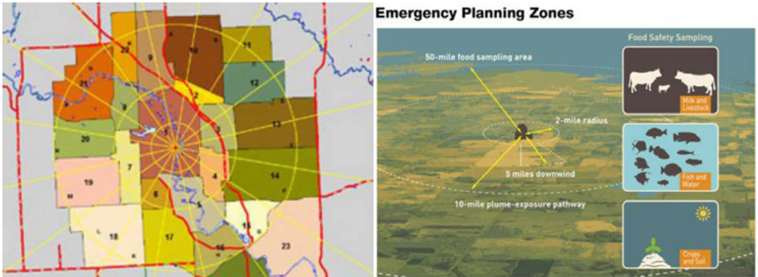
Figure 2 - U.S. Nuclear Regulatory Commission – Emergency Planning Zone
The SMR’s that can be installed as individual units such as small individual generating units of 50-70MW are characteristically applied to distributed generation. This presents a different problem for the physical location of the SMR and its associated substation. The bulk distribution substation and the small SMR and generator would need to provide required exclusion zones and security apparatus at that location, which could be in a more populated community area.
The physical location of hydrogen production facilities connected to the grid do not have any special physical requirements except for the regulations pertaining to high pressure gas storage facilities. These facilities may be located near substations.
The electrical connection point of an SMR and/or hydrogen production facility to the grid is important for several reasons.
With respect to SMRs, when they are grouped to form a large generator source they generally need to be connected to multiple high-capacity lines. This allows for the generation capacity to effectively be transmitted across the grid efficiently to multiple loads via multiple paths. This also provides for a reliable and redundant system. The interconnecting substation for the SMR generation would typically be the point in the system where the multiple high-capacity lines are physically close. In cases where the interconnecting substation would be located on a site with limited space, gas insulated substations may be an effective alternative with options for improved physical security. These high-capacity substations would be very similar to traditional large generator switchyards and would require similar capacity ratings.
SMR’s installed as individual units such as small individual generating units of 50-70MW that are connected to the grid via bulk distribution substations present a similar capacity requirement to the larger SMR switchyards. The difference is that the interconnecting bulk distribution substation will need to handle two-way power flows, both distribution loads and outfeed of SMR generation capacity to the transmission system. If a PEM electrolyzer is connected to the distribution bus at the substation to produce hydrogen, then additional capacity requirements will be needed at the substation.
The connected SMRs will need to be managed as critical Key Transmission Elements on the transmission system, since they are baseload generation resources. The SMR powered generators also provide the inertial stability, reactive power (VAR) support and voltage support to the electric system. The interconnecting substation basic design must be expandable, whether for a large SMR powered generator or a distributed generation source and provide simple substation switching to safely isolate facilities and employ equipment with minimum adverse impact on power flows. The design also needs to provide operating flexibility and most importantly availability of critical Key Transmission Elements. Some performance requirements are:
- Clearing a fault on a Key Transmission Element should not require the opening of a terminal of any other Key Transmission Element (unless a breaker failure also occurs).
- With all elements in service, clearing a fault on a bus section within the substation should not result in the opening of a terminal of any more than one Key Transmission Element.
- With all elements in service, a fault followed by the failure of any circuit breaker within the substation should not result in the opening of terminals of any more than two Key Transmission Elements.
- With all elements in service, the opening of any single circuit breaker should not open a terminal of a Key Transmission Element and should not split the substation into two isolated portions with no direct connection between them at the substation.
The breaker-and-a-half with double tie breaker or double-bus, double breaker substation arrangements satisfy these requirements. These arrangements are most prevalent for the larger transmission substations. For bulk distribution substations where small individual generating units of 50-70MW are connected, a ring bus arrangement may be sufficient, see Figure 3 [4].
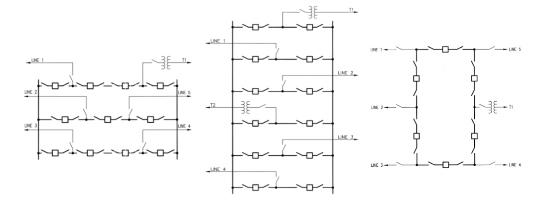
Figure 3 - Breaker-and-a-half with double tie breaker or double-bus, double breaker, and ring bus
3. Substation sitting
The advanced inherent safety features of SMRs may justify an emergency planning zone (EPZ) in the U.S. that only extends as far as the site boundary (as opposed to 10 miles for current U.S. nuclear plants), see Figure 4. This will allow the SMRs to be collocated with existing generating plants including repowering of retiring coal stations, large substations, and smaller bulk distribution substations. The reduction in EPZ will also allow for the colocation of the SMRs with hydrogen production facilities connected to substations, process heat off-takers and district heating near population centers. The level of SMR plant safety and resiliency that SMRs provide is appealing to hospitals, government installations, and digital data storage facilities that serve as mission critical infrastructure and need highly available and reliable electricity [5].
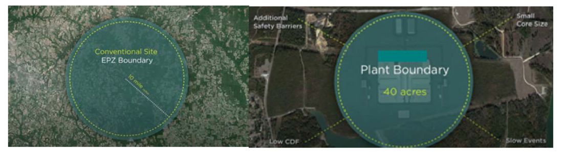
Figure 4 - Example comparison conventional EPZ to SMR EPZ
Public attitudes toward nuclear power are an issue for many regions that already contain or seek to develop nuclear power plants. Understanding the sentiment toward nuclear power in the immediate surrounding area is important to determine what actions and education are needed to ensure public support of the proposed SMRs. Community outreach developments can be a useful tool to help the public better understand the safety associated with advanced modular nuclear energy, and the benefits a proposed SMR can bring to a region [6].
4. Substation physical design for SMR connection
The approach and design of a substation connecting a large SMR to the grid at an existing or new generating facility is straightforward and like any other type of large generation resource. The only difference is that emergency planning zones and enhanced security need to be addressed. Large generating facilities that are utility or developer owned, already include provisions for separation of facilities between generation resources and the transmission system. These facilities are designed with interconnection ownership demarcation and include extensive physical security schemes and are designed with high resiliency in mind.
The SMR that is connected to the grid at a bulk distribution substation or local distribution substation will need to incorporate emergency planning zones and more advanced security systems than is typical. The SMR connected will require that there be a physical separation of facilities at the substation. Figure 5 shows a typical interconnection point at a bulk distribution substation for a generating plant or SMR located adjacent to the substation.
Figure 5 - Typical SMR interconnection point at a bulk distribution substation
These collocated SMR and substation facilities will require the typical visible break disconnecting devices for an interconnecting generator to a substation. The difference is that the operating jurisdictions will need to be well defined between the SMR facility and the interconnecting substation. These operating jurisdictions include above and beyond the typical demarcations, enhanced physical security zones and barriers between the SMR and substation.
The interconnection electrical design may include one or more circuit breaker and disconnect switch positions to observe system separation capability. The interconnection must be able to accommodate a base load capacity injection to the grid and accommodate excess power available to the grid system during off peak hours, since SMRs are always on. Connections of SMRs rated 50-70MW to substations may be either via overhead conductors, air-insulated bus bar, gas insulated bus bar or underground power cables.

5. Substation physical design for collocated hydrogen production connection
The approach and design of a substation connecting a hydrogen electrolyser to a substation in conjunction with an SMR at an existing or new large generating facility is straightforward. Large generating facility substations are designed with the capacity requirements to accept large distribution loads and are usually expandable to do so. These large generating facility substations include the provisions for separation of facilities between generation resources, local large distribution loads and the transmission system. They can also easily accommodate provisions for separation of large distribution load facilities such as hydrogen electrolysers. As with the connection of SMRs, the hydrogen electrolyser interconnection ownership demarcation and physical security schemes are designed with high resiliency in mind. The one difference associated with the connection of a hydrogen electrolyser to a substation is the need for setbacks, protective schemes, barriers, and procedures related to the storage of compressed gas.
The hydrogen electrolyser that is connected to the grid at a bulk distribution substation or local distribution substation with a collocated SMR will need to incorporate setbacks, protective schemes, barriers, and procedures related to the storage of compressed gas as well. The hydrogen electrolyser facility will be located within the emergency planning zone for the SMR and will require more advanced security systems than is typical. The hydrogen electrolyser collocated with the SMR, and substation will require that there be a physical separation of facilities at the substation. In many cases the hydrogen electrolyser facility will have its own small substation to transform the utility distribution voltage.
Figure 6 shows a typical interconnection point at a bulk distribution substation for a hydrogen electrolyser facility located adjacent to the substation [7].
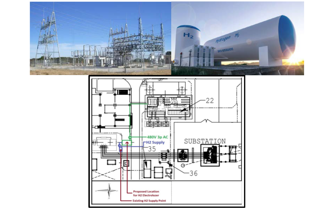
Figure 6 - Typical hydrogen electrolyser facility interconnection point at a bulk distribution substation
These collocated SMR, hydrogen electrolyser and substation facilities will require the typical visible break disconnecting devices for an interconnecting generator or large commercial distribution load to a substation. The operating jurisdictions will need to be well defined between the SMR facility, the hydrogen production facility, and the interconnecting substation. These operating jurisdictions include above and beyond the typical demarcations, procedures controlling emergency planning zones, enhanced physical security zones and barriers between the SMR, hydrogen production facility and substation.
The interconnection electrical design may include one or more circuit breaker and disconnect switch positions to observe system separation capability. The interconnection must be able to accommodate supplying the excess power available from the collocated SMR to the grid system during off peak hours and to power the hydrogen production facility via a dedicated feeder or feeders. The connection of SMRs rated 50-70MW to substations may be either via overhead conductors, air-insulated bus bar, gas insulated bus bar or underground power cables. Likewise, the connection of the hydrogen electrolyser to the substation may be via overhead conductors, air-insulated bus bar, gas insulated bus bar or underground power cables.
6. Substation protection and control impacts
The connection of an SMR (300-420MW) or (600-840MW) to drive larger electric generators or groups of generators to an existing generating facility substation, will require typical protection and control schemes that are used to connect any large generator to the grid system. Figure 7 shows the typical protective relay functions used in generator protection schemes that would be applied to a large SMR facility.
The generator control schemes will be typical as well and should minimally impact the interconnecting substation control system design. This is true for reactive power (VAR) supply and control. It is also true with respect to system stability and reactive power (VAR) support and voltage support, the larger SMRs with larger generators enhance system inertial stability and voltage stability.
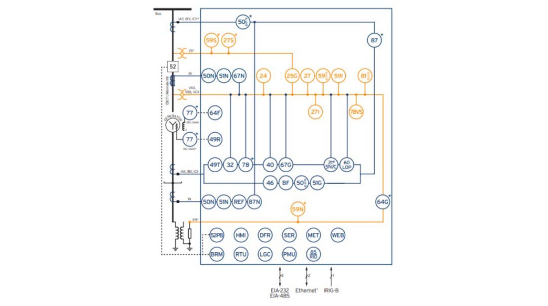
Figure 7 - Typical generator protection scheme [8]
These same typical generator protective relay functions would be used to connect SMRs rated 50-70MW to bulk distribution substations. Therefore, the protection and control impacts to the interconnecting substations for large and small SMRs may not be minimal, but they are typical. The hydrogen electrolysers that are collocated with SMRs at bulk distributiuon substations are treated as large industrial distribution loads that are connected to the substation distribution bus, usually via a dedicated feeder. Figure 8 shows the typical protective relay functions used for feeder protection schemes that would be applied to a large distribution load such as a hydrogen electrolyser.
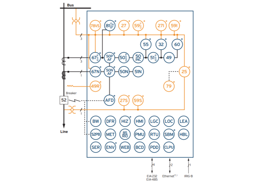
Figure 8 - Typical feeder protection scheme for a large distribution load [8]
In general, there are only minor impacts to the design substation protection and control schemes with respect to the connection of SMRs and hydrogen production facilities.
7. Substation equipment characteristics impact
The connection of an SMR (300-420MW) or (600-840MW) at an existing generating facility substation may require substation equipment upgrades at the generating facility switchyard. Additional circuit breaker positions and dedicated generator step-up transformer positions may need to be installed to accept the new generation.
Upgrades to existing generator facility switchyard equipment may be necessary. The connection of SMR powered generators may increase the available fault duty in the generator facility switchyard and require equipment and facility upgrades for increased short-time and interrupting capability. These upgrades may include but are not limited to the following substation equipment:
- Circuit breakers, short-time current capability and interrupting capability.
- Disconnect switches, short-time current capability.
- Insulators and bus supports, short circuit forces.
- Steel structures, mounting plates, anchoring plates/bolts and foundations, short circuit forces.
- Ground grid and grounding connections, short-time current capability.
- Instrument transformers, short-time current capability.
- Relaying, based on vintage and type of existing schemes.
Additional switching equipment may be required to provide for separation of facilities between the new SMR powered generation resources, local large distribution loads and the transmission system.
The SMR and collocated hydrogen production facility that is connected to the grid at a bulk distribution substation or local distribution substation will also require substation equipment upgrades. Additional circuit breaker positions and dedicated generator step-up transformer positions will need to be installed to accept the new generation. The collocated hydrogen electrolyser will require additional switching equipment and visible break disconnecting devices for a large commercial distribution load at the substation.
Upgrades to existing bulk distribution substation equipment may be necessary. The connection of an SMR powered generator may increase the available fault duty on the substation bus and require equipment and facility upgrades for increased short-time and interrupting capability. These upgrades may include but are not limited to the following substation equipment:
- Circuit breakers, short-time current capability and interrupting capability.
- Disconnect switches, short-time current capability.
- Insulators and bus supports, short circuit forces.
- Steel structures, mounting plates, anchoring plates/bolts and foundations, short circuit forces.
- Ground grid and grounding connections, short-time current capability.
- Instrument transformers, short-time current capability.
- Relaying, based on vintage and type of existing schemes.
In general, there can be significant impacts to the substation equipment with respect to the connection of SMRs and hydrogen production facilities to either existing generator switchyards or existing bulk distribution substations.
8. Conclusions
Small modular reactors (SMRs) connected to substations offer superior technology, reliability, and availability for the baseload power needs of any power grid. Figure 9 shows the advantages of SMRs as a baseload power resource.
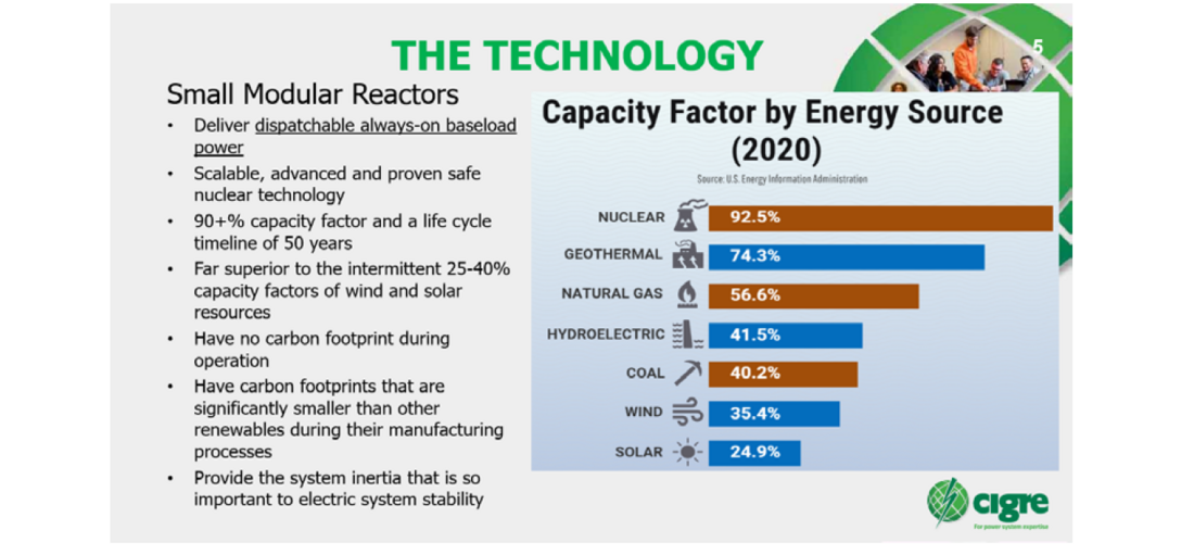
Figure 9 - Advantages of SMRs as a baseload power resource
The collocation of hydrogen electrolysers with SMRs connected to substations offers the ability to produce hydrogen during off peak hours to power vehicles, support industrial processes, support chemical processes, supply green hydrogen gas to the market and provide energy storage. Figure 10 shows the advantages of collocated hydrogen electrolysers with SMRs.
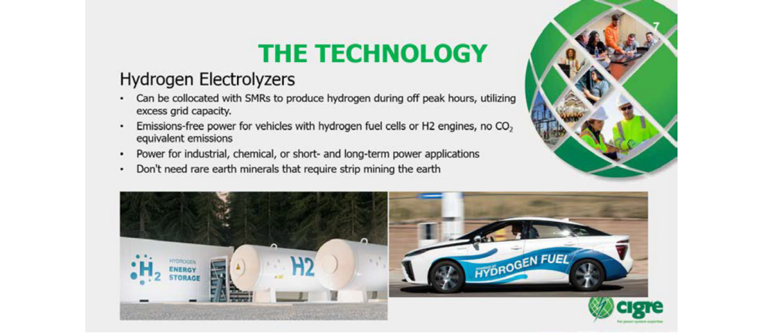
Figure 10 - Advantages of collocated hydrogen electrolysers with SMRs
The impacts of connecting SMRs and collocated hydrogen production facilities to the grid via substations are different based on the size and type of interconnection.
The connection of SMRs with collocated hydrogen production to the grid either individually, to existing generating stations, or to bulk distribution substations may necessitate special substation planning with respect to physical location and site characteristics. These substations may be required to be within emergency planning zones (EPZ) and higher security zones, which are different than a typical substation facility.
Ideally, the SMRs with collocated hydrogen production should be connected to multiple high-capacity lines to allow for the generation capacity to effectively be transmitted across the grid efficiently to multiple loads via multiple paths. The connected SMRs should be managed as critical Key Transmission Elements on the transmission system, since they are baseload generation resources and provide inertial stability, reactive power (VAR) support and voltage support to the electric system.
The advanced inherent safety features of SMRs may justify an emergency planning zone (EPZ) that only extends as far as the site boundary.
The connection of SMRs with collocated hydrogen production to the grid either individually, to existing generating stations, or to bulk distribution substations will require provisions for separation of facilities between generation resources and the transmission system. These collocated SMR and substation facilities will require the typical visible break disconnecting devices for an interconnecting generator to a substation. The operating jurisdictions will need to be well defined and above and beyond the typical demarcations, with enhanced physical security zones and barriers between the SMR and substation. The hydrogen electrolyser that is connected to the grid at a bulk distribution substation or local distribution substation with a collocated SMR will need to incorporate setbacks, protective schemes, barriers, and procedures related to the storage of compressed gas.
The protection and control impacts to the interconnecting substations for large and small SMRs may not be minimal, but they are typical. There are only minor impacts to the design substation protection and control schemes with respect to the connection of SMRs and collocated hydrogen production facilities.
Equipment and facility upgrades may be required to accommodate the connection of SMRs with collocated hydrogen production to the grid either individually, to existing generating stations, or to bulk distribution substations. These upgrades may include circuit breakers, disconnect switches, insulators/bus supports, steel structures/appurtenances, ground grid, instrument transformers and relaying. Additional switching equipment may be required to provide for separation of facilities between the new SMR powered generation resources, local large distribution loads and the transmission system.
In general, other than the need for emergency planning zones (EPZ) and higher security zones, which may only need to extend as far as the site boundary, the connection of SMRs with collocated hydrogen production to substations may be complex but is typical, as for any generation resource. The impacts associated with substation connections of SMRs, and collocated hydrogen production should not deter the implementation of these zero-carbon emission technologies. The connection of these technologies to the grid will most likely generate a paradigm shift that changes the approach and application of wind and solar energy systems on the grid, as replacements for base-load generation sources, to intermediate load or more likely peak load generation resources.
References
- https://www.energy.gov/ne/advanced-small-modular-reactors-smrs, 2023.
- https://www.energy.gov/eere/fuelcells/articles/us-department-energy-hydrogen-and-fuel-cell-technologies-office-overview, 2021.
- https://www.nrc.gov/about-nrc/emerg-preparedness/about-emerg-preparedness/planning-zones.html, 2023.
- ISO New England Planning Procedure No. 9, Major Substation Bus Arrangement Requirements and Guidelines, 2017. pp_9.pdf (iso-ne.com)
- https://www.nuscalepower.com/en/products/voygr-smr-plants, 2023.
- SMR Site Feasibility Study for LENOWISCO, R-203-2301-001-01 Revision 0, Dominion Engineering Inc., April 2023.
- https://www.powereng.com/library/planning-and-protection-approach-to-substation-physical, January 2023.
- Schweitzer Engineering Laboratories, 2022 Catalog, selinc.com, 2022.