C6 - Soft Open Point at Bermeo substation to improve distribution system reliability and hosting capacity
Authors
M. ZUBIAGA, J. CAÑAS - Ingeteam Research Institute, Spain
D. SANTOS, E. OLEA, J. CHIVITE - Ingeteam P. Technology, Spain
R. PEÑA - Iberdrola, Spain

Summary
A new Soft Open Point (SOP) with a rated power of 10 MVA is expected to enter service in 2024, at the 30 kV Iberdrola’s i-DE Bermeo substation, northern Spain. This is a joint project between Ingeteam and Iberdrola’s i-DE Redes Eléctricas Inteligentes (i-DE), within the activities of Iberdrola’s Global Smart Grids Innovation Hub. The Factory Acceptance Tests (FAT) including functional tests were carried out in September of 2023. This new link, based on power electronic Voltage Source Converters (VSC), has a back-to-back architecture, proven to be the most versatile option to enhance the operation of the existing distribution grids. It provides bi-directional active power flow between the two AC grids/grid points that are inter-connected and enables the independent control of reactive power at each point. Thus, by using active management techniques, such as following specific voltage profiles and power flow patterns, the installation releases unused grid capacity, to increase the hosting capacity. That is, to connect new generation to the grid and to improve the grid reliability. The paper analyses the increase of the hosting capacity, determined by key requirements specified in the Spanish MV regulations, such as over/undervoltage conditions in N, N-1 and N-1-1 contingency scenarios. It also shows how the operation can be improved with additional Black start and Grid Forming capabilities.
Keywords
Back to back converter, FACTS, Power electronics, Grid-connected converters, Hosting capacity, Power Systems, Soft Open Point1. Introduction
Two of the most important directives for distribution system operator (DSO) are: the secure and reliable operation of the grid under normal and contingency conditions, and to maximize the usage and capabilities of the existing power infrastructure, whist preserving quality of supply. These require the understanding and optimization of the assets, to maximize efficiency and hosting capacity without impairing the security of the system. In this context, optimization is understood as minimizing distribution losses and maximizing hosting capacity without undermining the system security.
A secure system must be able to survive several contingencies without violating the operating constraints. Contingency is referred to a disturbance resulting from components outages. Sudden changes in the system configuration can lead to severe violations of the operating constraints, potentially triggering a chain of events that may eventually lead to a partial or total blackout, or loss of supply.
The effect of power system component outages in terms of their severity and possible consequences is continuously analysed by system operators on a daily basis. The analysis considers all possible contingency scenarios, with special attention to the most severe, in order to apply a Remedial Action Scheme (RAS) for each one. The RAS aims for the system to withstand these contingencies and return into a secure state.
For example, the most common contingency criterion is the so-called N-1, broadly utilized in the power industry [1]. This criterion ensures that the system has the ability to go through any single component outage. Another broadly used contingency criterion is called the N-1-1. This criterion ensures the system ability to withstand two component outages applied sequentially rather than simultaneously. RAS actions start from small disturbances that may for instance require changing transformer taps and/or operating shunt capacitors/inductors, to the more severe disturbances that require drastic actions, such as load shedding, switching lines or connecting additional generation.
Power electronic devices can help with both of the aforementioned objectives, by applying active management techniques, they can optimize the use of the existing grid infrastructure and take active part in RAS actions. The power electronic solutions available in the market are analysed and compared in [2]. Solutions that imply back-to-back configuration combine the capability of controlling bi-directional active power transfer from one end to the other and independent control of reactive power consumption and production at each end. They allow the connection of different feeders not necessarily synchronized. In addition, related to the guarantee of supply, they may implement grid forming functions, getting the ability to feed isolated parts of the network (black start) or improve network stability. For abnormal situations such as fault events, this device works as firewall to current and there is no need to increase fault current rating and step-and-touch voltage of existing assets. In terms of sizing with the objective of controlling active power flow, series connection technologies (‘Static Series Synchronous Compensator’ SSSC and ‘Unified Power Flow Controller’ UPFC) have the ability to use less quantity of power electronic devices to reach the same effect on power flow, but this effect is highly dependent on network topology getting more impact in mesh grids. For the network configuration present in the area of Bermeo substation, the most versatile power electronics devices to optimize the existing infrastructure are the ones based on back-to-back configuration [2].
With regards to the nomenclature, references to back-to-back power electronics links in distribution networks, can be found using different acronyms and technical terms: Soft Open Point (SOP) [3]-[4], Flexible Power Link (FPL) [5], Medium Voltage Direct Current (MVDC) connection, Grid Inter-Tie Converter [6] or Interlinking Converters [7]. While all of them are similar, there are slight differences between them. According to the authors’ understanding, an interlinking converter is a more generic term that includes all kinds of power electronic devices used to link power systems (AC-AC,AC-DC and DC-AC). Also in a generic manner, Grid Inter-Tie Converters refer to devices used for interconnecting distant power systems.
The difference between an SOP and an MVDC connection relays in their application and scope [8]. An MVDC is mainly used on medium to long distance power transmission at the distribution system level, to ensure an efficient power transmission over extended distances. This type of connections can be considered as an adaptation of High Voltage Direct Current (HVDC) links to distribution grids. On the other hand, an SOP finds its main application in local and regional distribution grids, where it allows the management and control of power flows. Finally, FPL is the name given by Western Power Distribution (WPD), to a particular installation [5].
The SOP installed in the present project is connected between two double circuits of a 30kV line. By doing so, the SOP allows the balancing of power flows between both circuits and the voltage control at each terminal, similarly to a double STATCOM system. The installation also helps enhancing reliability, improving reliability figures such as the non-interrupted supply indicated with system average interruption duration index (SAIDI) and system average interruption frequency index (SAIFI). However, this latter advantage is out of the scope of the present publication.
2. Bermeo SOP case
i-DE Redes Eléctricas Inteligentes (i-DE), in cooperation with Ingeteam, are constructing a “Soft Open Point” at the 30 kV Bermeo substation, located in northern Spain, in a natural protected area close to Urdaibai Biosphere Reserve. This is one of the initiatives in the field of power electronics of the Global Smart Grids Innovation Hub, a global centre of innovation and knowledge in smart grids, devoted to respond to the challenges of the energy transition. This substation is connected through a double 30 kV line to the rest of distribution system at two points. One (Mungia) is located 17 km away, and the other (Euba) at 35km away. This substation also allocates an important generation node (Wartsila shipyards), in an area that has a relatively low level of demand, or industrial loads.
The factory acceptance tests (FAT) were carried out in September of 2023 at the Ingeteam high power laboratory located in Zamudio. These included functional tests, such as island detection, transition to GFM control and high-level controls. The FAT tests are outside the scope of this publication. Subsequently, the equipment will be translated to Bermeo substation during 2024, following successful granting or planning permission.
Prior to the launch of the project, an analysis of the grid area around Bermeo substation was carried out using PSS®E commercial software. Multiple different cases where analysed, including all possible N-1 contingency cases. These study cases are not only used to measure system reliability, they also give information on the hosting capacity, as required to grant access to the distribution grid. Hosting capacity is considered as the capacity of the grid to support generation (or demand) without violating the operating limits.
Prior to the connection of the SOP, the two most noticeable deviations from the regulations in the (N-1) contingency analysis are described below:
- For the “Consumption valley and generation peak Case” in (N-1) contingency conditions due to the trip of line 2 at Mungia Substation, overvoltage violations appear at Wartsila1 (V=1.09 pu), STR Bermeo (V=1.086 pu) and STR Bakio (V=1.087 pu). This indicates that system requires a device to support voltage control. This case is represented in Figure 1.
- For the “Consumption peak and generation valley Case” in (N-1) contingency conditions due to the trip of line 1 at Mungia Substation, undervoltage violations appear at Wartsila1 and Wartsila 2 (V=0.835 pu), STR Bermeo (V=0.836 pu), STR Bakio (V=0.824 pu) and STR Gernika (V=0.899 pu). This indicates that the system requires a device to support voltage control. Moreover, consumption loads need also readjusting to alleviate overloads, Figure 2.
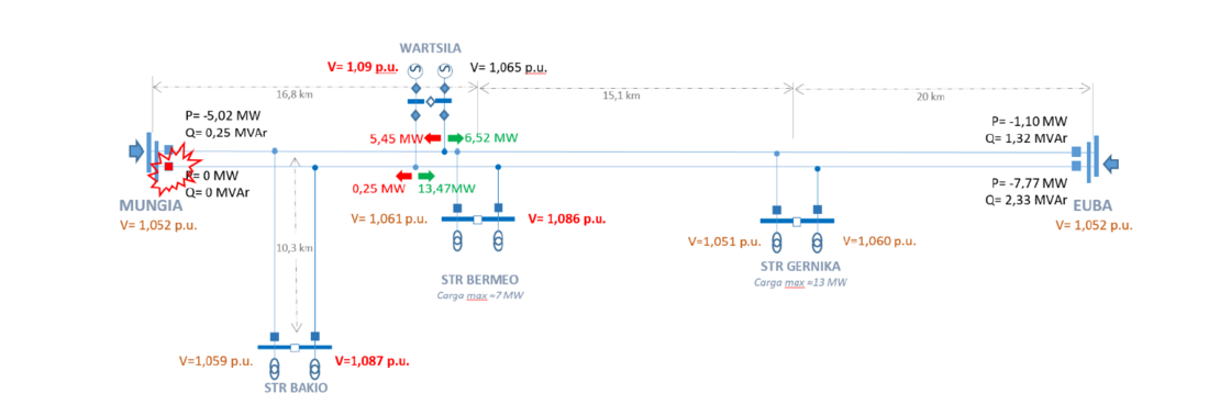
Figure 1 - Mungía-Euba distribution grid at N-1 contingency in Mungía Substation. Consumption valley and generation peak Case
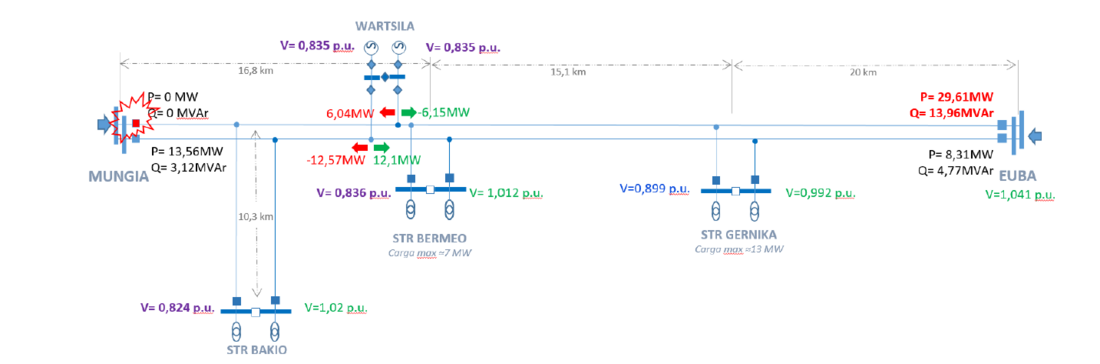
Figure 2 - Mungía-Euba distribution grid at N-1 contingency in Mungia Substation. Consumption peak and generation valley Case
The system is almost at its maximum hosting capacity for loads and generation. In line with this hosting capacity limit, N-1 contingency conditions lead to severe grid operating constrain violations. The construction of an additional line to future-proof the energy needs of the areas close to this biosphere reserve may endanger the protected natural area. Equally, inaction may hinder economic growth.
The distribution system operator (i-DE) already has in place other devices to solve these issues, such as breakers and tap controlled transformers. Those devices are much slower than the SOP and they do not allow managing the power flows flexibly to solve the hosting capacity issue.
The 2 x 5 MVA SOP (Figure 3) will be placed at a Normally Open Point (NOP) between the double 30 kV lines at Bermeo substation, thus allowing the transfer of active power between the lines when a line is heavily loaded. The SOP can also export or import reactive power independently on each side, working similarly to two STATCOMs connected at each side. Instead of a single 10 MVA installation 2 x 5 MVA solution have been selected in to use the full flexibility potential of the double line. This allows the connection between lines or segments of the same line depending on the status of the breakers, opening new ways to experiment with the advanced features of the SOP device.
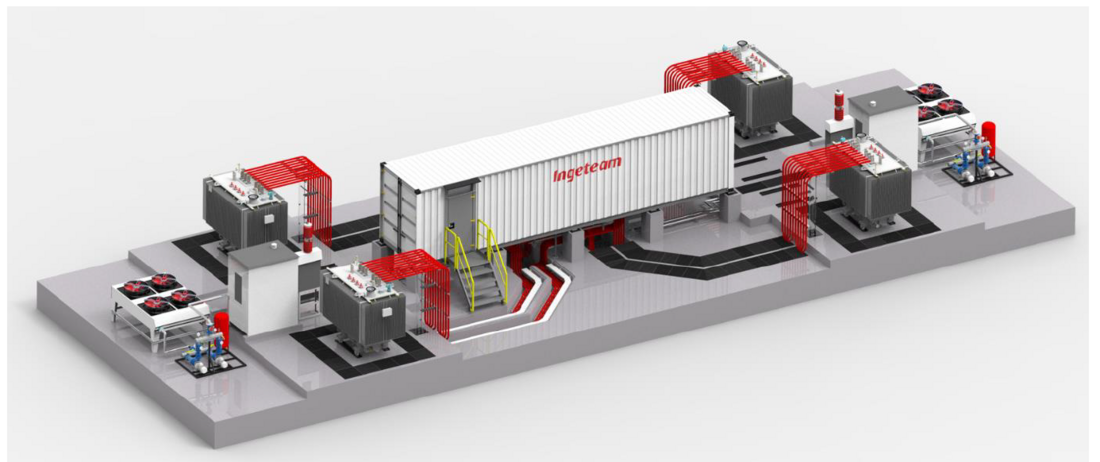
Figure 3 - Ingeteam SOP based on two Ingegrid LV800 inverters [9]
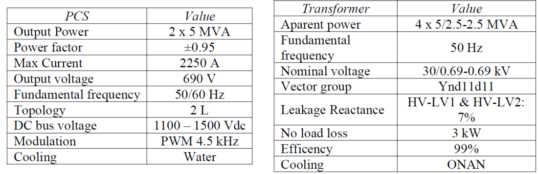
Table I - Inverter and transformer characteristics
To show the benefits of the SOP installation, the analysis of the two previous cases seen in Figure 1 and Figure 2, has been repeated, but this time including the 10MVA SOP. The results are significantly improved as the voltages and load levels remain this time within operational constrains. The new voltage and load distributions are shown in Figure 4 and Figure 5 for the two previous worst-cases.
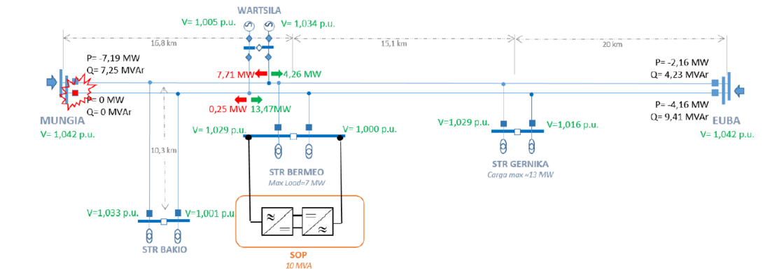
Figure 4 - Mungía-Euba distribution grid at N-1 contingency in Mungia Substation. Consumption valley and generation peak Case with an SOP
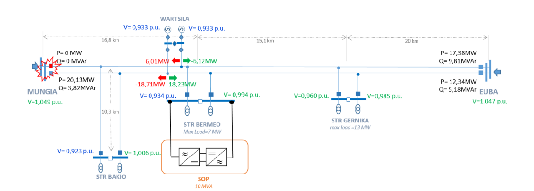
Figure 5 - Mungía-Euba distribution grid at N-1 contingency in Mungia Substation. Consumption peak and generation valley Case with an SOP
Considering a 10 MVA SOP at Bermeo substation, the system is no longer in its limits at the N-1 contingency case. Making the system more reliable and increasing hosting capacity.
In Spain the addition of new generation is regulated by the BOE-A-2021-9231 [10]. The conditions to accept a new access capacity in the distribution grid for this particular case (<36kV) has to meet the following 5 criterions:
- The injected additional active power at the specific node can not cause any overloads in any element of the distribution grid or voltages that exceed the regulatory limit. For the present analysis ±7%.
- The grid must maintain its electrical characteristics within the following limits in the event of a N-1 contingency:
- No overloads in any line of the distribution grid above their seasonal thermal limit.
- No overloads in the transformers of the distribution grid with respect to their nominal power.
- The voltages do not exceed the regulatory limits. For the present analysis +10%/-15%.
- The maximum power allowed to inject for the total generation connected to a line, considering all the generators connected, will not exceed 70% of feeder thermal capacity.
- When connecting or disconnecting abruptly, the voltage variation of the node cannot be higher than 3%. For simultaneous disconnection of the generators connected to the same node, the voltage variation of the node cannot exceed ± 5.5 %.
- The ratio between the short-circuit power calculated at the node, and the maximum capacity of all connected generators, should be less than a pre-defined minimum value.

The DSO should analyse those 5 criteria for the most critical situations. For the connection of the new generation, the most critical situation recommended is the operation point when the demand is in a valley situation. The following study scenario is recommended:
- Valley demand situation, which can be considered as 55% of the maximum demand if no specific data is available.
- Maximum generation: All the connected generation at 90% of its nominal capacity, except at the connection point under study, which will be considered at 100% of its nominal capacity.
In order to calculate the per-node non-concurrent generation hosting capacity, h, the maximum generation for each node, should be supported without violating any of the aforementioned 5 criteria. This is expressed as the following equation (1) – (5):
(1)
(2)
(3)
(4)
(5)
Where: Vi is the voltage at i node without contingency conditions, V min is the minimum node voltage without contingency conditions, V max is the maximum node voltage without contingency conditions, ViN-1 is the voltage at i node at N-1 contingency, VN-1min is the minimum node voltage at N-1 contingency, VN-1 max is the maximum node voltage at N-1 contingency, ???? is the active power at line feeder, is the thermal limit of line feeder, ΔVi is the voltage variation of the node i when simultaneous disconnection of the generators connected to the node occurs, ΔVmax is the maximum allowed voltage variation at any node when simultaneous disconnection of the generators connected to the node occurs, SCR/geni is the ratio between the short-circuit power calculated at the node i and the maximum capacity of all connected generators at node i and SCR/genmin is the minimum allowed ratio between the short-circuit power and the maximum capacity of all connected generators at any node.
The simulations were performed using PSS®E commercial software. Considering the power system without the SOP, the Bermeo and Gernika substation can only host an additional generation power of 4MW and 9MW respectively. As shown in Figure 6, following the SOP installation, the hosting capacity is expected to increase in Bermeo from an additional 4MW to 16 MW, and in Gernika from 9MW to 21MW. This increased generation capacity at each substation is non-concurrent, in the sense that adding new generation at any substation, may affect the hosting capacity at its neighbouring substations and after any system change, the hosting capacity should be re-calculated [11].
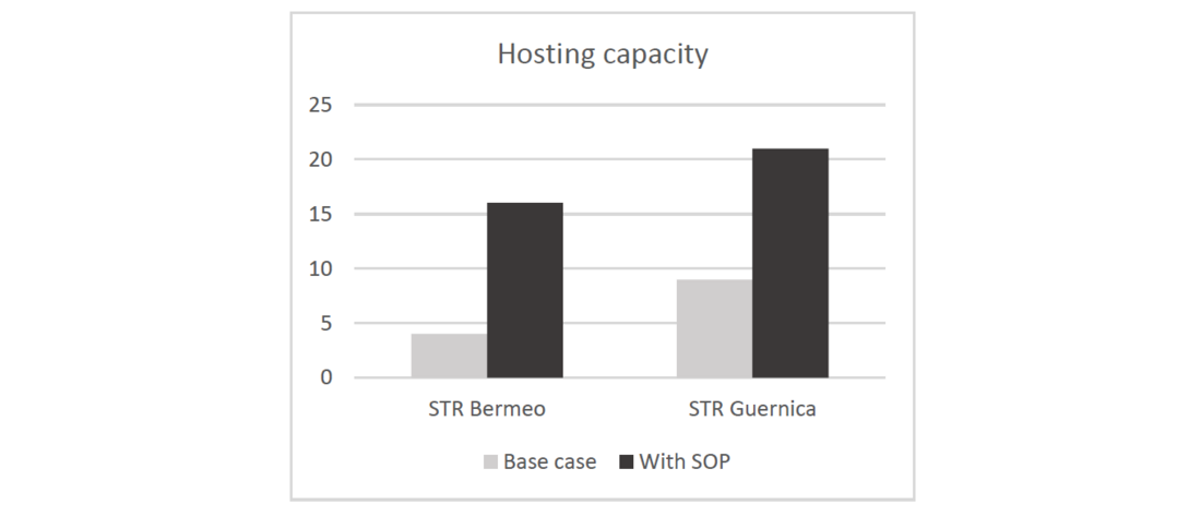
Figure 6 - Non-concurrent hosting capacity at Bermeo and Gernica with and without an SOP
This additional capacity will allow the development of the urban areas close to the Urdaibai Biosphere Reserve in the future. The construction of a new line to improve the hosting capacity and alleviate the maximum grid voltage violations at the protected area is avoided by optimizing the already existing infrastructure using an SOP.
The SOP can also increase the reliability for consumers at the Bermeo substation by enabling islanding operation. Furthermore, the island mode operates without ESS (Energy storage system) in the system, as the energy is taken from the main grid through the DC link. Finally, for the N-1-1 case which is very unlikely, the SOP allows the black start of one of the lines. This is described as follows.
Island Enabling SOP (with no energy storage)
When the SOP detects autonomously an island condition on one side, and providing an external signal enables this operating mode, the control for that side of the SOP switches to from Grid FoLlowing mode (GFL) to Grid ForMing (GFM) control. In GFM the SOP supplies the grid, maintaining stability and nominal electrical characteristics (voltage and frequency) within the island. The active power to supply the grid comes from the opposite side and is transferred through the DC link. This avoids the use of ESS, but generates a dependency on the main grid. This is shown in Figure 7 below.
The Island Enabling SOP functionality could also perform the safe re-synchronization and reconnection of the island to the main network. The SOP will operate as a centralised island controller and will be responsible for the following control functions of the island:
- Synchronisation and re-connection of the island to the main grid;
- Transient stability control to ensure the frequency and voltage of the island remain within operational limits.
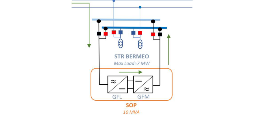
Figure 7 - The SOP at Bermeo substation and the breakers to allow the island operation
Black Start from N-1-1
Although the N-1-1 case is highly unlikely, it may probably lead to a partial or total blackout of the area. To help during the recovery process, the SOP will provide black start capability by feeding the part of the line that has suffered the blackout, an example is shown in Figure 8. To do so, the following actions and stages will be made for the service resumption.
- System energization: the SOP will start increasing the voltage from zero with a controlled ramp. In this way, transformers and other connected loads can be gradually energized without generating high inrush currents. The SOP is sized to provide the initial power needed to energize the system.
- Grid Synchronization: once system is energized, the next step is to synchronize with the main power system. This involves aligning the frequency, voltage, and phase angles of the island with the main grid. Synchronization ensures a smooth transition and prevents disturbances when breakers are closed to feed the newly re-started area from the main grid.
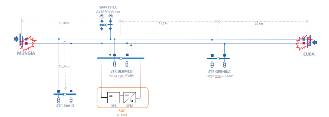
Figure 8 - Mungía-Euba distribution grid at N-1-1 contingency
3. Conclusions
The SOP will provide flexibility to the local grid, controlling the power flow between the lines with accuracy. This will achieve a more efficient utilization of existing infrastructure as the hosting capacity of the distribution grid is increased. This increase has been analysed and quantified to be greater than the rated power of the SOP, in the present case, by at least 1.2 times. Furthermore, the SOP can regulate both, voltage and reactive power while controlling the active power flow. This helps improve system stability and reduce the risk of voltage and frequency fluctuations.
The grid’s reliability is also improved by the SOP by providing alternative paths for the power flow. Some key event related to N-1 and N-1-1 scenarios have been analysed, showing that the SOP ensures the continuity of supply, minimizing the risk of widespread outages. The SOP can also feed part of the network in islanding mode operation. Moreover, depending on its configuration and power rating, it can also take over an island without having to go through a zero voltage transition. The island feed / formed by the SOP, can be controlled and re-synchronized with the main grid in a secure manner, making the island formation and re-connection seamless, almost transparent for the users.
In summary, the SOP to be installed at the Bermeo substation is expected to improve the reliability and to maximize the use of the existing grid infrastructure. It will allow the local community around the Urdaibai area, classed by UNESCO as a biosphere natural reserve, to develop their economy, prosper, and future proof their energy needs, without jeopardizing the natural environment.
References
- Abul'Wafa, Ahmed R., Aboul’fotouh El'Garably and Shazly Nasser. “Power System Security Assessment under N-1 and N-1-1 Contingency Conditions.” International Journal of Engineering Research and Technology. ISSN 0974-3154, Volume 12, Number 11 (2019), pp. 1854-1863.
- J. M. Bloemink, T.C. Green, “Benefits of distribution-level power electronics for supporting distributed generation growth”, IEEE Transactions on Power Delivery, April-2013, doi:10.1109/TPWRD.2012.2232313
- P. Favre-Perrod, C. Dour, M. Allani, L. Eggenschwiler, A. Bifrare, M. Carpita, “Soft-Open points for Medium Voltage Networks – A Case Study”, 25th International Conference on Electricity Distribution - CIRED, June-2019.
- R. Wu, L. Ran, G. Weiss, J. Wu, “Control of a synchronverter-based soft open point in a distribution network”, The Journal of Engineering, April-2019, doi: 10.1049/joe.2018.8382
- J. Berry, “Trialling and Demonstrating the FPL method – V1”, Western Power Distribution, September-2018.
- R. Bernacchi, “MVDC and Grid Interties: enabling new features in distribution, sub-transmission and industrial networks”, ABB Power Grids, November-2019.
- A. Ordono, E. Unamuno, J.A. Barrena, J. Paniagua, “Interlinking converters and their contribution to primary regulation”, Elsevier – Electrical Power and Energy Systems, April-2019, doi:10.1016/j.ijepes.2019.03.057.
- E. Olea-Oregi, P. Eguia-Lopez, A. Sanchez-Ruiz, and I. Loureiro-Gonzalez, “Industrial Overview of Back-to-Back VSC Power Links in MV Distribution Networks,” IEEE Trans. Smart Grid, pp. 1–1, 2022, doi: 10.1109/TSG.2022.3187157.
- Ingeteam catalogue, “INGEGRID Static Synchronous Compensator” available online [last access June 2023]
- Agencia estatal Boletin Oficial del estado, available online [last access June 2023]
- L.J. Thomas, A. Burchill, D.J. Rogers, M. Guest, N. Jenkins, “Assessing distribution network hosting capacity with the addition of soft open points”, IET 5th International Conference on Renewable Power Generation, 2016