C4 - Grid forming functional specifications and verification tests for North American bulk power system connected battery energy storage systems
Authors
Aung THANT, Hongtao MA - NERC, USA
Andrew ISAACS, Lukas UNRUH - Electranix, Canada
Ryan QUINT - Elevate Energy Consulting, USA
Deepak RAMASUBRAMANIAN - EPRI, USA
Julia MATEVOSYAN - ESIG, USA
Andy HOKE - NREL, USA

Summary
Studies have shown that grids dominated by inverter-based resources (IBR) in the absence of synchronous resources need a portion of the IBR resource mix to be grid forming (GFM) to maintain stable operation [1, 2]. Extrapolating from the challenges smaller islands face today and their experience with specifying GFM inverters as one of the core strategies to maintain stability, it is expected that the need for GFM technology will accelerate very quickly with the rapid growth of IBRs across North America and around the world. A major obstacle of deploying GFM on the bulk power system (BPS) is establishing clear specifications and interconnection requirements regarding the performance, test procedures, and validation of GFM technology. This paper provides the following contributions in this space:
- Outlines unique opportunities for enabling GFM in battery energy storage systems (BESS) to provide critical grid-stabilizing characteristics.
- Introduces a functional specification specifically for GFM in BPS-connected BESS.
- Introduces a simple yet effective GFM functional test system that grid planners can use to verify GFM characteristics for newly interconnecting resources.
- Provides test results of the functional specification and test system using original equipment manufacturer (OEM)-provided models of their GFM and conventional grid following (GFL) BESS controls.
The paper is a culmination of work conducted by industry partners as part of the North American Electric Reliability Corporation (NERC) Inverter-Based Resource Performance Subcommittee (IRPS) to ensure reliable operation during the energy transition [3].
Keywords
battery energy storage system, grid forming, inverter-based resource, modeling1. Background
GFM technology has been around for many years mainly in islanded systems or microgrids; however, defining GFM for bulk power system applications has posed a challenge for industry. NERC defined GFM controls for BPS-connected IBRs as [4]:
Controls with the primary objective of maintaining an internal voltage phasor that is constant or nearly constant in the sub-transient to transient time frame. This allows the IBR to immediately respond to changes in the external system and maintain IBR control stability during challenging network conditions. The voltage phasor must be controlled to maintain synchronism with other devices in the grid and must also regulate active and reactive power appropriately to support the grid.
A GFM inverter’s control objective in the sub-transient time frame (e.g., 0-5 cycles after a disturbance) is to maintain internal voltage phasor magnitude and angle and to prioritize the support of terminal voltage. This provides a resistance to change in the external system and thereby grants certain stabilizing properties. Therefore, GFM inverters do not maintain fixed active or reactive power during that timeframe[1]. On longer timeframes, a GFM inverter must also synchronize with other sources. Both GFM and GFL inverters will pursue other objectives such as following active and reactive power set points, frequency response, voltage regulation, etc., and both must operate within voltage and current limits as well as primary energy source availability.
2. Benefits of enabling GFM controls in BPS-connected BESS
Interconnection queues in the United States had over 680 GW of BESS capacity (standalone BESS and part of hybrid plants) at the end of 2022 [5]. The authors are not aware of any operational or planned North American BPS-connected BESS with GFM controls enabled given the absence of requirements or incentives for GFM capability, although the technology is commercially available across multiple OEMs. Many BESS will be deployed in IBR-dominated areas with existing stability constraints. Installing these resources as GFL will likely reduce stability margins and could result in new stability constraints, leading to potential curtailment of low-cost generation. Installing newly connecting BESS as GFM could help alleviate these constraints in tandem with other network upgrades such as synchronous condensers, GFM STATCOM with energy storage, or new transmission lines. However, it is important to note that GFM BESS offers a least-cost solution that will societally reduce overall energy costs to consumers.
GFM controls provide grid stabilizing characteristics that support reliable operation of the BPS under increasing penetration of IBRs. Enabling GFM in BPS-connected BESS allows for system-wide enhancement of stability margins as these resources are interconnected. Therefore, system stability enhancements can be achieved at much lower cost than through the addition of transmission assets. While GFM controls can be implemented on any type of IBR including solar photovoltaic and wind plants accounting for some limitations, adopting GFM controls in BESS is a particularly low-hanging fruit for supporting BPS reliability since they already have the needed energy buffer on the dc side. This makes the enhancement purely software-based, essentially minimizing or entirely eliminating any incremental project costs for newly connecting resources.
While some areas, like the Hawaiian Islands [6], already need to enable GFM BESS to maintain grid stability and prevent large-scale outages, many areas of the United States are reaching relatively high penetrations of IBRs now or in the future and will face similar challenges. Industry is faced with a unique window of opportunity to procure, test, and gain experience with GFM technology now before significant adverse reliability issues arise in the future due to the lack of sufficient GFM resources.
3. Functional specifications defining grid forming BESS
Table 1 outlines functional specifications often applied to both GFL and GFM BESS connected to the BPS such as dispatchability, steady-state voltage control, dynamic reactive power support, active power-frequency control, disturbance ride-through performance, fault current and negative sequence current contribution, and physical and cyber security requirements. The functional specifications specific to BPS-connected GFM BESS include the following:
- GFM-Specific Voltage and Frequency Support: GFM shall provide autonomous, near-instantaneous frequency and voltage support by maintaining a nearly constant internal voltage phasor in the sub-transient time frame, including:
- Phase Jump Performance: GFM shall resist near-instantaneous voltage magnitude and phase angle changes by providing appropriate [2] levels of active and reactive power output in the sub-transient time frame.
- System Strength Support: GFM shall help reduce the sensitivity of voltage change for a given change in current in the sub-transient time scale.
- Ability to Stably Operate with Loss of Last Synchronous Machine: GFM shall be capable of operating stably through and following the disconnection of the last synchronous machine in its portion of the power grid [3].
| Capability | Grid Forming | Grid Following |
|---|---|---|
| Sub-cycle Voltage and Frequency Support | ✓ |
|
| Phase Jump Resistance | ✓ |
|
| System Strength Support | ✓ |
|
| Ability to Stably Operate with Loss of Last Synchronous Machine | ✓ |
|
| Dispatchability | ✓ | ✓ |
| Steady-state Voltage Control | ✓ | ✓ |
| Dynamic Reactive Power Support | ✓ | ✓ |
| Active-Power Frequency Control | ✓ | ✓ |
| Disturbance Ride-Through Performance | ✓ | ✓ |
| Fault Current and Negative Sequence Current Contribution | ✓ | ✓ |
| Cyber and Physical Security | ✓ | ✓ |
The functional specifications defined above are applicable when the BESS is within its limits of the energy source behind the inverter and the equipment ratings of the inverter [4]. The functional specifications do not impose requirements for fault current capability beyond equipment ratings. GFM BESS shall also continue providing GFM operational characteristics even at highest and lowest allowable state of charge. If the BESS remains connected to the network, it shall remain in GFM mode. There should be no state of charge condition where the BESS should need to operate in GFL mode. Lastly, performance requirements for BPS-connected IBRs (e.g., IEEE 2800-2022 [7]) may also apply to GFM resources unless explicitly stated by the local interconnection requirements. To the extent that existing requirements in IEEE 2800 may create any barriers to GFM applications, exceptions may need to be considered.
Additional desirable performance characteristics for GFM that are not included in this functional specification at this time due to present technology considerations include the following:
- Passivity: GFM should present a non-negative resistance and a passive characteristic to the grid within a wide frequency range (e.g. 5–300 Hz) to prevent adverse interactions. Interactions with other generation on the system, including other GFM BESS, as well as interactions with the power system as a whole, can and should be identified and addressed through interconnection studies.
- Negative Sequence Current during Continuous Operating Region: GFM should provide negative sequence current.
- Balanced GFM Internal Voltage: GFM internally generated voltage should remain balanced during all near-nominal operating conditions (e.g., 0.9–1.1. pu voltage).
GFM and blackstart-capable are not synonymous terms yet GFM is a prerequisite for an IBR to be eligible for blackstart capability. Therefore, blackstart is not included in the GFM functional specification but any blackstart requirements specific to IBRs should include provisions for GFM capability among other aspects such as extended short-term overcurrent, more stringent ride-through, longer energy duration capabilities.
4. GFM functional performance verification tests
Although there is general consensus on a definition of GFM, opinions differ regarding how to qualify a newly connecting resource as GFM and how to test for GFM capability. GFM can be specified in a number of ways such as defining control topology, specifying quantitative response metrics, using frequency domain characterization, or using a set of test procedures. This paper proposes and defines a set of test procedures that transmission planners can effectively implement to ensure GFM functionality is provided for newly connecting BESS. The tests and criteria are not intended to be overly prescriptive. They are intentionally designed to be simple to implement and agnostic to GFM control topologies.
While any particular GFM BESS may not be subjected to the simulated events in real-time operation, the test procedures ensure that the GFM controls provide the necessary grid-stabilizing characteristics. For example, GFM BESS can be subjected to severe external events that are generally difficult or impossible for GFL BESS to stably operate through. Similarly, GFM BESS can continue serving load with the disconnection of all other synchronous machines. These are operating conditions that conventional GFL IBR controls are generally not able to support.
The functional performance verification tests determine whether an interconnecting BESS can be classified as GFM. These tests can be integrated as part of the interconnection study process to establish GFM requirements for newly interconnecting BESS. Generator owners, project developers, and OEMs can ensure that planned facilities meet these functional specifications prior to interconnection studies, which will help expedite the process. Verifying GFM functionality with test simulations (referred to herein as “GFM functional tests”) using accurate and detailed EMT models provided and certified directly from the OEM is necessary, in addition to inverter unit model validation, attestations and detailed descriptions of the control modes from the OEMs [8, 9, 10].
4.1. Description of GFM Functional Test System
The GFM functional test system (see Figure 1) consists of the following components connected to a single bus without any impedance:
• A synchronous generator with a simple excitation system model (e.g., SCRX) and turbine-governor model (e.g., TGOV1), with circuit breaker
• A load [5] with both active and reactive power (inductive) components, with a maximum power factor of 0.9
• The GFM BESS plant model under test
• A duplicate of the GFM BESS plant model, rated at or near half (MVA and MW) of the model under test [6].
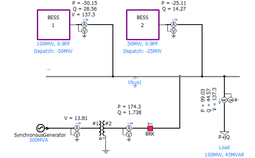
Figure 1 - GFM Functional Test System
The combined MVA rating of the BESS models must be sufficient to fully supply the load upon disconnection of the synchronous generator. The synchronous generator MVA rating must be sufficient to simultaneously serve the load and charge both BESS at their rated maximum charge power. Both BESS models should be in voltage control mode with the same voltage and frequency droop settings and set points. All protection settings in the BESS should reflect the equipment planned to be installed in the field; however, settings should be set as wide as possible within the equipment ratings and capabilities (as recommended in NERC reliability guidelines [8, 11, 12]) since the tests may subject the GFM BESS to extreme frequency, voltage, and phase jump events.
4.2. GFM functional tests and success criteria
Using simulated disturbances that only a GFM BESS meeting the functional specifications could survive, the following suite of GFM functional tests are designed to ensure that each proposed project meets the GFM BESS functional specifications [7].
- Test 1 – BESS Initially Discharging and Ends at Higher Level of Discharging: This test assesses the GFM BESS performance following the generator trip when operating within its limits and in discharging state.
- Test 2 – BESS Initially Charging and Ends Up Discharging: This test assesses the GFM BESS performance when operating within its limits and transitioning from charging state to discharging state after the generator trips.
- Test 3 – BESS GFM Performance at Maximum Active Power: This test assesses the GFM BESS performance following the generator trip when operating at or near its limits.
Each test is conducted using different initial operating conditions, as outlined in Table 2. Once the system is stable at the given power flow conditions (without oscillations), the synchronous generator is disconnected. Each test then includes a set of pass/fail success criteria that must all be met (also see Table 2). TPs/PCs should add additional qualitative or quantitative criteria specific to their own systems, as applicable. GFM BESS under test must pass all three tests to qualify as GFM [8].
Although the tests require the BESS to be operated in the absence of any synchronous generation, many GFM BESS will never be operated that way. Regardless, the ability to survive such tests indicates that the controls have the necessary properties of GFM in grid-connected conditions. Conversely, if the resource is unable to meet the performance requirements in these tests, the controls will not have the desired characteristics for future BPS operating conditions.
These tests do not guarantee that the facility will be stable for a specific location on the grid. Interconnection studies are critical for ensuring reliable operation of the BPS for each specific interconnecting resource [9]. If settings change during interconnection studies, the model with the new settings should still pass these tests.
| Initial Dispatch |
| Test 1: • The project BESS and the duplicate BESS are dispatched at 20% of their maximum discharge power limit. Test 2: • The project BESS and the duplicate BESS are dispatched at 50% of their maximum charge power limit. Test 3: • The project BESS is dispatched at 0 MW. The duplicate BESS is dispatched at its steady-state maximum discharge power limit. |
| Test Sequence: |
| • Run until the system is stable at the given power flow conditions, without oscillations. • Trip the synchronous generator. |
| Success Criteria |
| Pre-Trip: |
| • Each BESS’s active power output matches dispatched levels. |
| • Synchronous generator active power output matches the rest of the load. |
| • Frequency should be 1 pu. |
| • Voltage at Bus 1 should be within 5% of nominal. |
| • Phase voltage and current waveform should not be distorted. |
| • There should not be oscillations in the root mean square (RMS) quantities. |
| • Reactive power output from all devices should be within limits. |
| Post-Trip: |
| • Immediately following the trip, BESS output should be well controlled. System frequency and voltage should not oscillate excessively or deviate from steady-state levels for any significant amount of time. |
| • Voltage settles to a stable and acceptable operating point |
| • The final voltage is as expected based on the droop and deadband settings. |
| • Frequency settles to a stable operating point. |
| • The final frequency is as expected based on the droop and deadband settings. |
| • Any oscillation shall be settled. |
| • Any distortion observed in phase quantities should dissipate over time. |
| Test 1 and 2: • Active power from each BESS should move immediately to meet the load requirement and settle according to its frequency droop setting. Test 3: • Active power from BESS 1 should move immediately to meet the load requirement and settle according to its frequency droop setting. Active power from BESS 2 should not exceed its max discharge power limit at steady state. |
| • Reactive power from each BESS should move immediately and settle according to its voltage droop setting. |

4.3. Example conducting GFM functional tests
To illustrate conducting the GFM functional tests, an OEM-provided GFM inverter model, including a power plant controller model, was subjected to Test 2 as outlined above. Table 3 shows the BESS voltage and frequency droop settings used for this test.
| Parameter | Value |
|---|---|
| Voltage Droop | 2% (on Qmax) |
| Frequency Droop | 2% (on Pmax) |
| Frequency Deadband | 0.03 Hz |
The test system is initialized as described in Table 1. Figure 2 [10] shows the RMS quantities of the Test 2 simulation results including bus voltage (Vbus1_rms), frequency, synchronous generator active power (P_SyncGen), load active power (P_Load), project BESS (BESS 1) active power (P_BESS_1) and duplicate BESS (BESS 2) active power (P_BESS_2), reactive power, and current. The following observations are made:
- Near-instantaneous jump in active and reactive power from both BESS (see Point 1), followed by dynamics driven by specific GFM control topology and parameters
- Minimal deviation in voltage thus resulting in small change in voltage-dependent load power (see Point 2)
- Final steady-state quantities (see Point 3 for values indicated by O-marker at t = 40 sec in Figure 2) can be verified against the droop parameters in Table 3.
- Due to the larger differences between initial output power level and final settled output power level, driven by load, the frequency settled according to the frequency droop setting.
- Frequency spike (see Point 4) is an artifact of frequency measurement algorithm in response to the shift in voltage phase angle (see Point 1 in Figure 3).
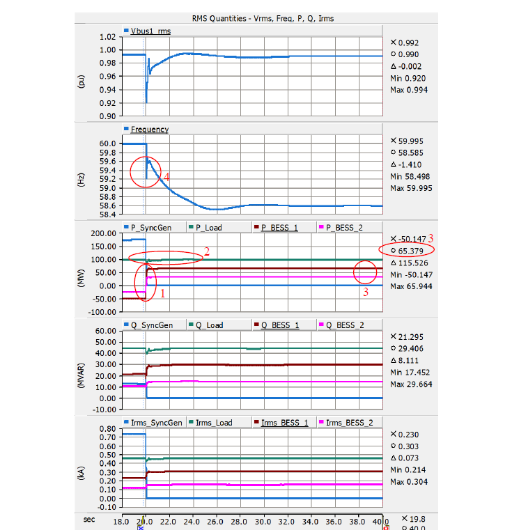
Figure 2 - Example Test 2 Results – RMS Quantities
The following observations can be made from Figure 3 which shows the instantaneous quantities of the Test 2 simulation results, including bus voltage (Vbus1), synchronous generator current (I_SyncGen), load current (I_Load), BESS 1 current (I_BESS_1) and BESS 2 current (I_BESS_2).
- Phase angle shift in bus voltage (see Point 1)
- Current from both GFM BESSs increased within a quarter-cycle to make up for the loss of synchronous generator current (see Point 2).
- Change in BESS current phase angle as BESSs transition from charging to discharging within a quarter-cycle to serve the load (see Point 3).
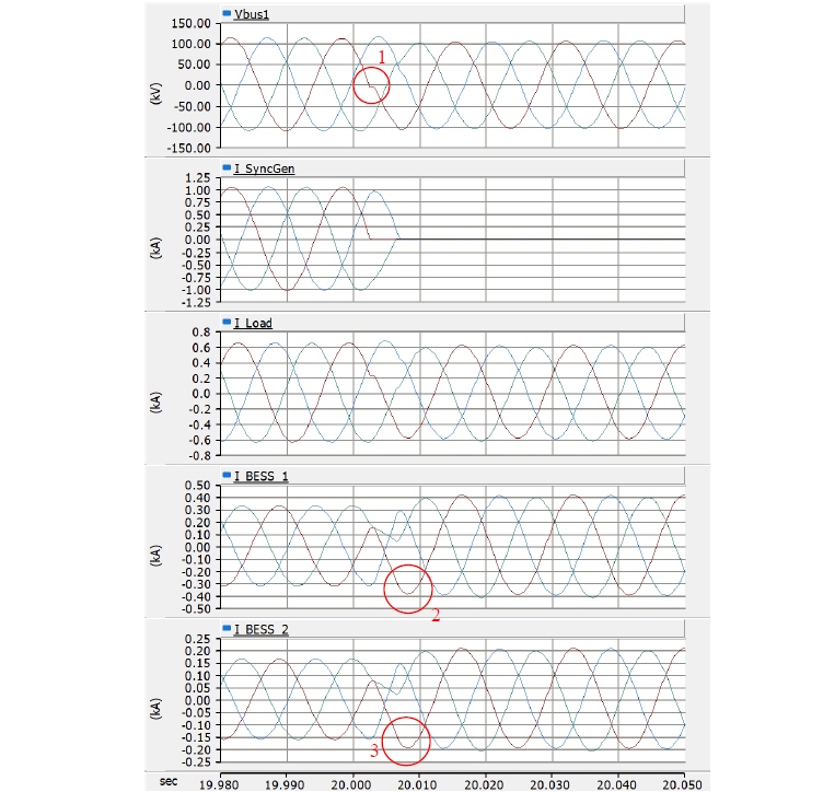
Figure 3 - Example Test 2 Results – Instantaneous Quantities
4.4. Illustration of Performance Comparison between GFM and GFL BESS in Functional Tests [11]
To illustrate the response of a grid following BESS for comparison with GFM, the same EMT model is put through Test 1 on the same test system with GFM functionality disabled. Frequency and voltage trip settings were widened to demonstrate the unstable behavior. Figure 4 shows GFL BESS goes unstable after the loss of the last synchronous generator, failing Test 1 criteria.
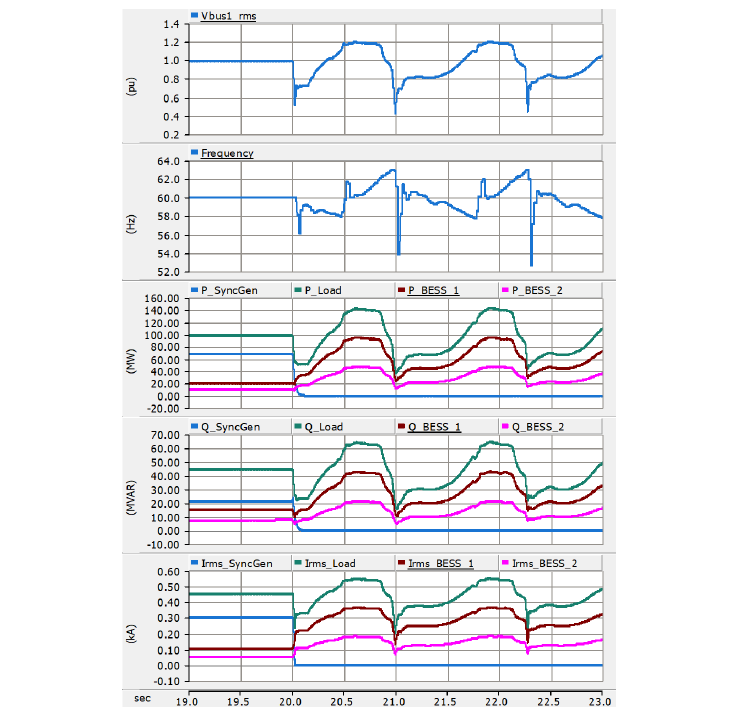
Figure 4 - Example Test 1 Results with GFL BESS
The following observation can be made from Figure 5 and Figure 6:
- Sub-cycle response in GFM current that GFL does not provide (see Point 1 in Figure 5.)
- Fast active and reactive power response from GFM that GFL does not provide (see Point 2 in Figure 6)
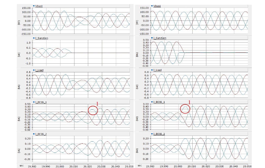
Figure 5 - Comparison between GFL (Left) and GFM (Right) Performance – Instantaneous Quantities
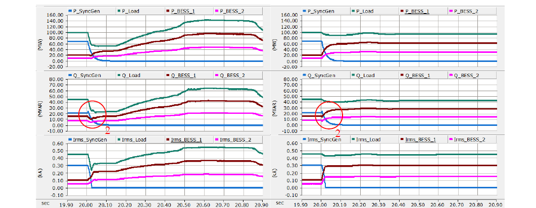
Figure 6 - Comparison between GFL (Left) and GFM (Right) Performance – RMS Quantities
5. Conclusion and future work
This paper presents a functional specification for GFM technology in BESS and a set of novel test methods that transmission planners can easily implement to verify GFM capability in BESS. The approach focuses on quantifiable performance while remaining agnostic to control topology which allows ongoing innovation in this space while enabling effective procurement of grid stabilizing characteristics from GFM BESS. The functional specification and test methods will more effectively enable adoption of GFM technology across the North American bulk power system, and can also be applied to other power system around the world.
Using the example tests with OEM-provided EMT models of a GFM BESS, the paper illustrates how the test methods can be implemented and the results can be assessed against the proposed success criteria. The example tests demonstrate and differentiate the unique characteristics of GFM BESS from GFL BESS. Although these tests were specifically created for BESS, similar tests could also be developed for GFM solar and wind resources as those technology evolve [14], as well as extending the work towards other types of resources such as STATCOM and HVDC. As such, the authors will explore adapting the described test methods for solar and wind resources in the future work.
References
- MIGRATE, “New Options in System Operations”, (Deliverable 3.4, January 2019)
- A. Hoke et al., "Stabilizing Inverter-Based Transmission Systems: Power hardware-in-the-loop experiments with a megawatt-scale grid-forming inverter," (IEEE Electrification Magazine, vol. 10, no. 3, pp. 32-44, Sept. 2022)
- NERC, “White Paper: Grid Forming Functional Specifications for BPS-Connected Battery Energy Storage Systems” (September 2023)
- NERC, “Grid Forming Technology, Bulk Power System Reliability Considerations” (December 2021)
- J. Rand et al., “Queued Up: Characteristics of Power Plants Seeking Transmission Interconnection As of the End of 2022.” (April 2023)
- Cameron Kruse, Alston Dcosta, “Lessons Learned from Inverter-based Grid Forming Operation” (UNIFI Seminar Series, October 2022)
- "IEEE Standard for Interconnection and Interoperability of Inverter-Based Resources (IBRs) Interconnecting with Associated Transmission Electric Power Systems," (IEEE Std 2800-2022, vol., no., pp.1-180, 22 April 2022)
- NERC, “Reliability Guideline Electromagnetic Transient Modeling for BPS-Connected Inverter-Based Resources - Recommended Model Requirements and Verification Practices,” (March 2023)
- V. Gevorgian et al., "Testing GFM and GFL Inverters Operating With Synchronous Condensers," (2023 IEEE Power & Energy Society General Meeting, Orlando, Florida, USA, July 2023)
- ARENA, “Report: Hornsdale Power Reserve Virtual Machine Mode Test Summary,” (September 2022)
- NERC, “Industry Recommendation Inverter-Based Resource Performance Issues,” (March 2023)
- NERC, “Inverter-Based Resource Performance Issues Report: Findings from the Level 2 Alert,” (November 2023)
- Shah, Shahil, et al. “Frequency Scans for GFM Performance Verification.” No. NREL/PR-5D00-87061. National Renewable Energy Laboratory (NREL), Golden, CO (United States), 2023
- V. Gevorgian, “Grid Forming Wind: Is it Ready for Prime Time?,” (22nd Wind and Solar Integration Workshop, Copenhagen, Denmark, September 2023)
- [1] On the other hand, GFL controls in the sub-transient time frame maintain a constant output current phasor magnitude and angle with adjustments to maintain the active and reactive power injection into the network. Hence, GFL does not maintain fixed voltage magnitude or phase angle on those timescales.
- [2] As an example, if the phase difference between the inverter terminal and the grid increases, the resource should increase (or make less negative) its active power injection in the sub-transient time scale. If the phase difference reduces, it should result in a reduction of its active power injection in the sub-transient time scale.
- [3] While generation capacity in the system can still meet the load
- [4] Transient conditions can cause GFM BESS to reach current limits, resulting in transient behavior that differs from the GFM performance characteristics described above
- [5] Constant impedance load model is used in the example test described later in the paper
- [6] The purpose of adding the duplicate BESS is to consider control interaction between multiple GFM devices, including droop response and to provide flexibility in post-event power balancing. While using an identical model for the second GFM BESS can ascertain it is feasible to run the tests without singling out any other specific technology, it does not test the ability of the BESS under test to operate stably with other types of resources. This can and should be addressed through more detailed test networks and interconnection studies.
- [7] TP/PC may require additional tests such as load rejection, faults, etc.
- [8] GFL BESS can potentially form an island with load under very specific power flow and resonance conditions. Hence, it's important to subject the project model to all three tests.
- [9] Other tests such as ride-through capability, voltage control, etc., are necessary to be conducted for all resources, including GFM and GFL.
- [10] RMS quantities are calculated by sampling instantaneous waveform and buffering in a moving window with the size of one cycle of the fundamental frequency. Frequency is measured according to IEEE C37.118 (PMU) protocol with moving window averaging.
- [11] The same GFM functional tests described in this paper are used for consistency. There are other methods available such as frequency scans for comparison of frequency domain characteristics [13].