Role of Inverter-Based Resources (IBRs) in energizing remote generating stations
Authors
L. SUNDARESH, D. RAMASUBRAMANIAN, V. SINGHVI - Electric Power Research Institute, Palo Alto,California, USA
H. CAMACHO, M. ARIFUJJAMAN, F. TIRU, M. W. KNOBBE - Southern California Edison, Westminster, California, USA
W. YAN, V. GEVORGIAN, S. SHAH - National Renewable Energy Laboratory, Golden, Colorado, USA

Summary
The increasing integration of Inverter-Based Resources (IBRs) into the system has brought significant focus on their role in blackstart and restoration procedures. Their advantageous features, such as low startup power requirements, operational flexibility across a wide range of power factors, rapid controllability, and the ability to energize a network at lower voltage levels necessitate a reassessment of existing restoration protocols. This paper seeks to showcase how IBRs can utilize their grid-forming capabilities to provide power to a remote generating station through detailed EMT simulation studies using data collected from an existing portion of a network.
Keywords
Inverter -Based resources, blackstart procedure, restoration, grid-forming inverter technology1. Introduction
The majority of current restoration procedures have been tailored for blackstart resources characterized as synchronous machines [1]. These plans have been fine-tuned to capitalize on the favorable traits of synchronous machines, such as inertia and substantial fault current, while addressing concerns related to their limited reactive power absorption capability. However, with the growing integration of Inverter-Based Resources (IBRs) into the generation mix, it is imperative to reassess the restoration plans. IBRs have different characteristics compared to synchronous machines like faster controls but lower fault current contribution and inertia, and employing the same procedures may prove suboptimal [1,2].
IBRs have several characteristics that are beneficial during restoration [3]. Their initial power requirement to restart a plant is much less than that of most conventional generators and there are far fewer steps involved during the start-up. Thus, the start-up time for an IBR-based black start resource will be shorter. IBRs can be developed to operate in the grid forming mode, which will enable them to blackstart a path independently [3]. IBRs also have the flexibility to operate as grid-forming STATCOMS with the ability to operate over large leading and lagging power factor with no constraint on minimum active power output that will support the energization of long transmission lines during early restoration, which has been traditionally avoided owing to the reactive power limitations of synchronous generators. However, limited current capability, possible control interactions with other generators, and lack of inertia also pose challenges to the black start process [4].
One of the capabilities of IBRs that is particularly useful during blackstart is its ability to increase the output voltage in a controlled manner [5]. This process of energizing part of the network at a lower voltage level (e.g., 30%) and gradually increasing voltage to normal levels before picking up load is referred to as soft energization. By following this process, high currents from the magnetization of large transformer units; and large switching transients can be reduced. Thus, this technique will reduce the restoration time by bypassing the need to energize additional generators and aid in restoring power to far away critical loads. However, this method will complicate fault detection and needs to be validated in practical field tests.
The paper aims to showcase how IBRs can utilize their grid-forming capabilities to blackstart a segment of an existing network with (Extra High Voltage) EHV lines to energize auxiliary loads in a remote generating station. While detailed on-site tests can be conducted in some systems, the critical nature of this portion of the network makes simulation studies the only feasible option. Therefore, detailed Electromagnetic Transient (EMT) domain simulation studies were conducted [6] to verify the blackstarting process. Extensive data collection and validation were conducted to faithfully replicate the existing conditions. Several scenarios have been developed to study the impact of limited availability of IBRs on system restoration.
The paper is organized as follows: Modeling of the cranking path is described in Section II. The results of the simulation studies are presented in Section III. A sensitivity analysis to study the impact of unavailability of IBRs is discussed in Section IV, and the paper is concluded in Section V.
2. Modeling of cranking path
Cranking path
The goal of the blackstart study was to energize the auxiliary motor loads in a generating station using an IBR. The cranking path of the utility’s network is shown in Fig. 1. The black start unit has to energize two large transformers and a 500 kV transmission line of length 80 miles in order to provide power to the target load. The key challenge is to mitigate the effects of the inrush currents generated during energization of transformers and capacitive current injection due to energization of the EHV line.
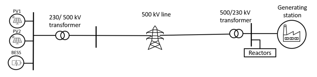
Figure 1 - Cranking path
Inverter model
The diagram of the control topology used is shown in Fig. 2 and Fig. 3. This inverter model has both grid forming (GFM) and grid following (GFL) capabilities [7-9] . In the GFL operation mode, the outer loops are droop-based. This approach enables parallel operation of multiple IBRs by adjusting their power output based on grid frequency and voltage, ensuring stable sharing of real and reactive power among droop-controlled voltage or current sources. The outer-loop PI compensators control the active and reactive power, and they further generate current references for the inner-loop current controllers. A Phase-locked loop (PLL) obtains the grid voltage angle, θ, required for synchronization. On the other hand, for GFM operation mode, as shown in Fig. 3, voltage controllers are implemented on top of the current controls instead of power controls, as done for GFL operation mode. The current references are generated to regulate inverter output currents, and they provide a current-limiting function to ensure that insulated-gate bipolar transistor (IGBTs) employed in the inverters are not damaged. For the grid forming controller, active power-frequency and reactive power-voltage droop controls are implemented as active and reactive power loops, with droop coefficients of m and n, respectively. The frequency of voltages is controlled by droop characteristics, and it further adds a nominal angular frequency to derive phase θ.
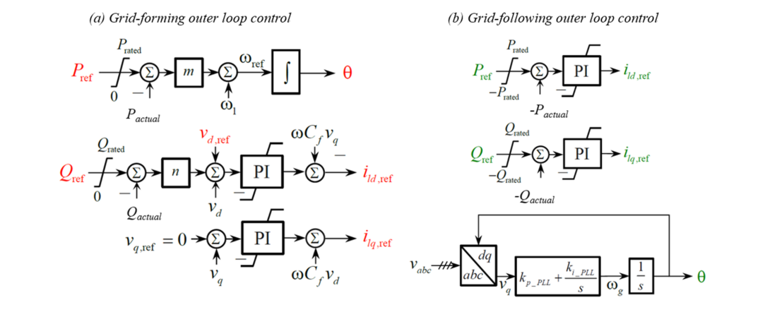
Figure 2 - GFM/GFL inverter outer-loop control diagram. (a). Droop-based GFM outer-loop control; (b). GFL outer-loop power control and PLL
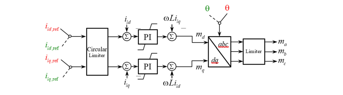
Figure 3 - GFM/GFL inverter inner-loop current control diagram
Transformer model
The key parameters of the transformers present in the network and are shown in Table 1. Apart from the two network transformers and the auxiliary transformer in the generating station, 3 additional transformers were included in the network to represent the generator step-up transformers for the inverters. The rating was assumed to be 110% of the inverter MVA rating.
| Name of the transformers | MVA Rating | Leakage Reactance | Winding configuration |
|---|---|---|---|
IBR transformers | |||
BESS GSU transformer | 440 | 0.085 | Delta -Y (grnd) |
PV1 GSU transformer | 330 | 0.085 | Delta -Y (grnd) |
PV2 GSU transformer | 275 | 0.085 | Delta -Y (grnd) |
Network transformers | |||
Station 1 transformer | 1120 | 0.1555 | Y(grnd) -Y (grnd) |
Station 2 transformer | 1120 | 0.1555 | Y(grnd) -Y (grnd) |
Generating station transformers | |||
Auxiliary transformer | 27 | 0.1 | Delta -Y (grnd) |
In order to accurately study the effect of transformer energization [10,11], the following parameters will have to be known:
- Magnetizing current
- Air core reactance
- Saturation Knee voltage
- Remnant flux in each of the cores
In practice, these values cannot be precisely estimated as they vary based on various factors like the manufacturer, year of manufacture, age of transformers, climate etc. For this study, typical values based on engineering judgement and guidance have been assumed as shown in Table 2.
| Parameter Name | Value |
|---|---|
Air core reactance | 0.1 p.u. |
Magnetizing current | 0.1% |
Knee voltage | 1.15 |
Loop width | 10 |
Remnant flux | 0.0 |
Transmission line model
The transmission lines in the network are modeled using frequency-dependent line model [12,13]. The frequency-dependent line models require the following information:
- Tower details (Structural details): The tower structure selected for this model was based on publicly available information. Depending on the terrain and the requirements of the area, different structures are used in practice. For the purposes of this study, a single circuit lattice steel tower was used.
- Conductor details (Material, strand details): The conductor parameters in the model were also based on the publicly available information [12,13].
- Length and impedance values of line: The length and impedance values were obtained from the utility and were used to verify the conductor details. The parameters were verified using the solve constants option in the frequency-dependent model and verified with the values provided to us.
Generator auxiliary load
The target energy project is a natural gas power plant. These are natural gas-fired combustion turbine generators (CTGs) that can start in 10 mins [14]. The details regarding the size and locked rotor current of the motors, and the size of auxiliary transformers were obtained from the field. Accordingly, 6 individual pumps and compressors were modeled using the standard 3-phase induction motor model as shown in Fig. 4.
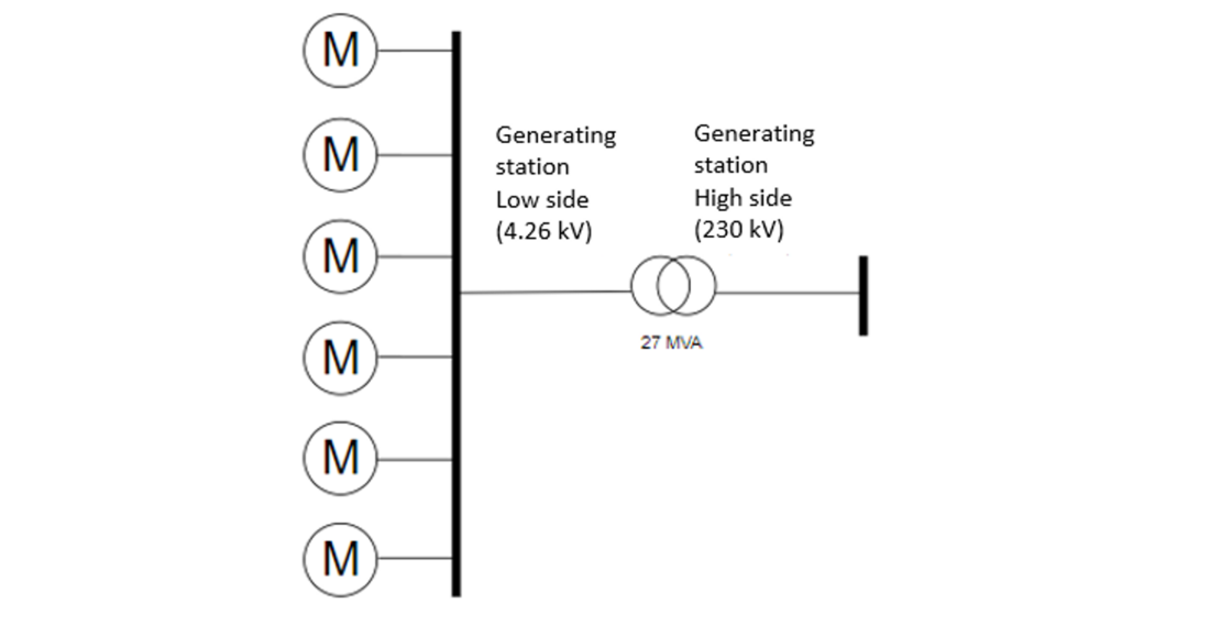
Figure 4 - Motor loads of the generating station
Motor loads in this case study represent either compressor or pump loads [14-16]. Typically, compressor/ pump type motor loads are categorized as National Electrical Manufacturers Association (NEMA) type B. NEMA Class B motors have a maximum 5% slip, starting torque is usually in the range of 150-200% of full load torque, their maximum torque in the range of 200-300 % full load torque and starting current that is 6 times the rated current [12].
Another critical assumption is that these motors are started with the load connected. Most motors are connected to the loads and therefore assuming no load start might provide optimistic results. Detailed modeling of the load torque of the motors is beyond the scope of the paper. However, a ramped starting load characteristics were included for the all the motors.

3. Simulation studies
Simulation studies were conducted with a time step of 5us. This time step was chosen based on the smallest frequency-dependent line model present in the system. The switching transients were not needed for the specific objectives we were trying to achieve in this paper; thus, neglecting a detailed model would have been more appropriate for the study. Thus, the average model was considered. Saturation is enabled for all of the network transformers. Soft starting was used to initialize the network till the load terminal. Initial load torque for the three-phase motors in the non blackstart units is assumed to ramp from 0 to 1 (per unit) p.u. in 1 s. The sequence of switching is shown in Table 3.
| Sequence | Time |
|---|---|
Synchronize the IBR plants | 2-5 seconds |
Energize the 230/500kV transformer | 10-11 seconds |
Energize 500kV Line | 12-15 seconds |
Energize the 500/230kV transformer | 16-17 seconds |
Increase the voltage to 1 p.u. | 18-19 seconds |
Energize motors sequentially | 31-45 seconds |
The waveforms recorded at the IBR transformer high side is shown in Fig. 5 and the load side waveforms to observe the motor starting transients are shown in Fig. 6.
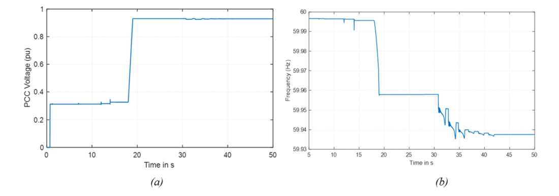
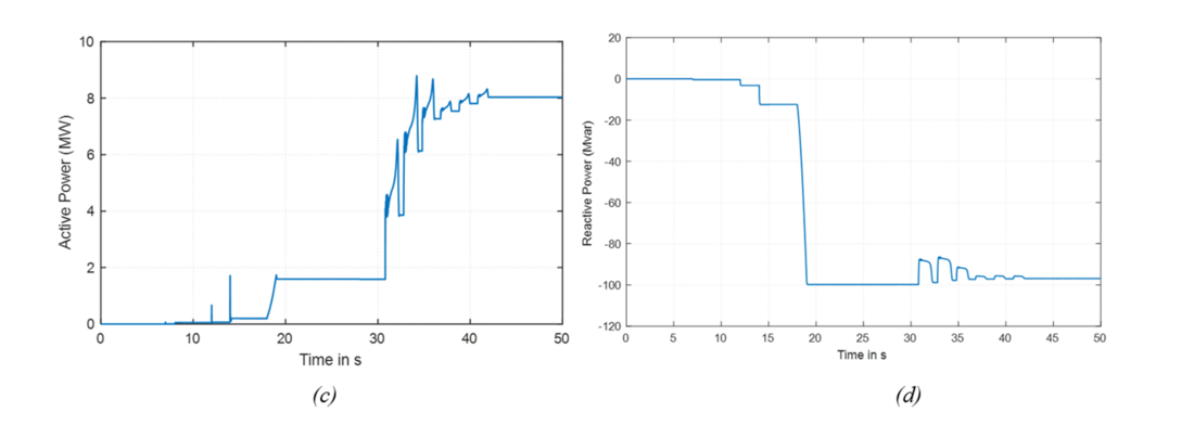
Figure 5 - Waveforms at Inverter transformer high-side
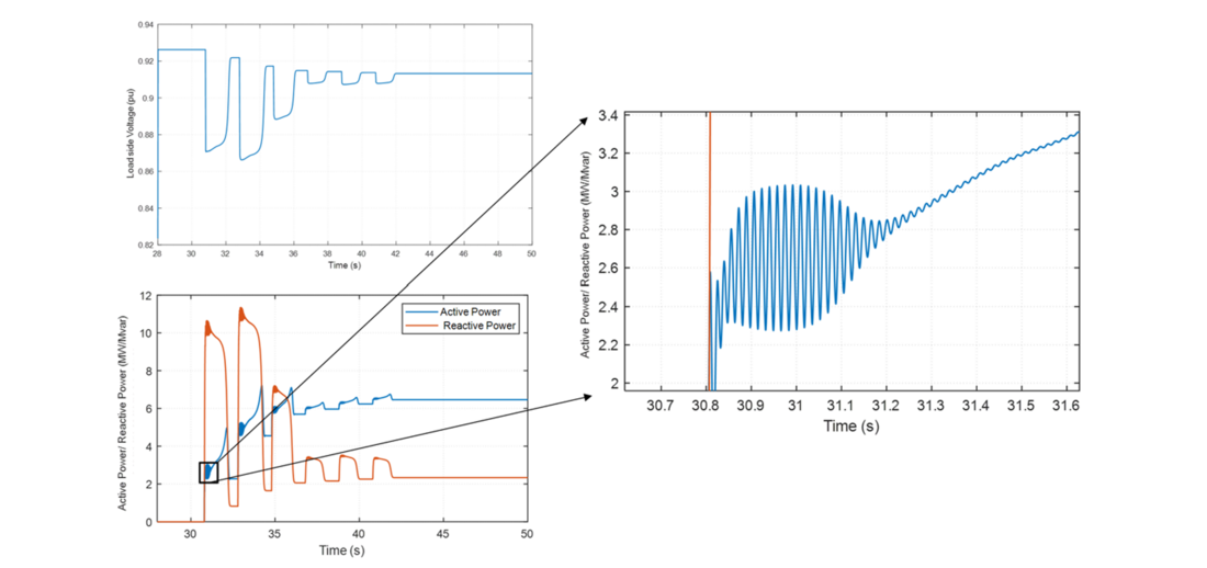
Figure 6 - Motor starting transients
The key takeaways from the simulation study are as follows:
- Fig. 5(a) shows that during the initial stages of the process (voltage is maintained at 0.3 p.u.) no large switching transients can be observed.
- Fig. 5(a) shows that after the voltage is increased to 1 p.u., the voltage remains within 0.9-1.1 p.u. during the load energization process.
- Fig. 5(b) indicates that the frequency remains between 59.9—60 Hz during the entire process of energization.
- Fig. 5(c) and Fig. 5(d) demonstrate that the with soft energization, the impact of inrush current and switching transients on inrush power is limited.
- Generator auxiliary load was successfully energized.
- Fig. (6) shows that the inrush currents during the starting of the induction motor are captured.
- The IBRs could provide sufficient current to ensure that all motors started successfully, and no significant voltage dip was observed.
4. Comparison of the case studies
Considering the intermittent nature of the PV resources and the possibility that all of these IBRs may not have grid-forming capability, three additional case studies were also done to study the impact of limited availability of IBRs and possible interactions if some of them are configured to only function in grid-following mode. The details of the scenarios are shown in Table 4.
| Scenario | Description |
|---|---|
Base Scenario | Use of both PV and BESS in grid forming mode as blackstart resource |
Scenario 1A | Use of one PV and BESS in grid forming mode as blackstart resource due to non-availability of resource |
Scenario 2A | Use of only BESS as blackstart resource in grid forming mode due to non-availability of PV |
Scenario 3A | Use of BESS as blackstart resource in grid forming mode and one PV in grid following mode |
The waveforms recorded at the IBR transformer high side is shown in Fig. 7.
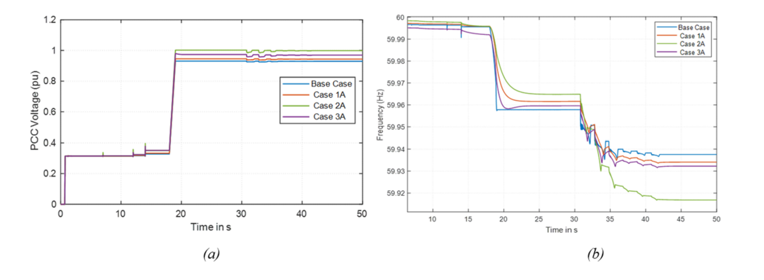
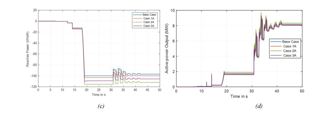
Figure 7 - Waveforms at Inverter transformer high-side (Comparison of cases)
The key takeaways from the simulation study are as follows:
- With soft energization, the 400 MVA capacity of BESS is sufficient to successfully energize the generator auxiliary load.
- Fig. 7 (a) indicates that under all the IBR scenarios, the terminal voltage remains above 0.9 p.u. during the entire blackstart process. Voltage temporarily dips during motor energization but recovers within 2s.
- Fig. 7 (b) indicates that under all the IBR scenarios, the frequency remains above 59.9 Hz during the entire procedure. Based on the available resources and the droop characteristics, the settling frequency for each of these scenarios changes.
- No adverse control interactions were observed between IBRs operating in GFM and GFL mode (Case 3A).
- All the motors in the generator station could be successfully energized.
- With the reduction in the total amount of blackstart resources available online:
- Frequency settled at a lower value for the same amount of load energization.
- Larger changes in voltage magnitude were observed during the energization of lines or inclusion of loads.
5. Conclusions
A detailed EMT simulation study successfully demonstrated IBRs’ capability to initiate the restoration of a real network segment. This study showcased the effectiveness of IBRs in black starting- a process essential for power grid restoration. A soft energization approach was employed to address challenges such as line charging and transformer inrush. This method ensured the gradual energization of auxiliary loads located in a remote generator substation. Despite a reduction in the total amount of available online blackstart resources, the network could be energized using soft starting.
However, there is a need for further investigation and potential mitigation strategies to ensure the robustness of IBRs during the restoration process, particularly in scenarios involving EHV lines. The following studies are recommended to ensure the robustness of the blackstart plan:
- Tune the control parameters of the inverter resources to optimize the energization and avoid unstable oscillations.
- Incorporate dynamic load models with cold start characteristics (loss of diversity, inrush currents).
- Conduct fault studies and study the impact of limited current capabilities of IBRs on the system response.
- Sensitivity studies for motor starting under various conditions.
- Analyze the protection settings needed to avoid mis-operations of the relays.
References
- “System Restoration Procedure and Practices” CIGRE, TB 712, Dec. 2017.
- Integrate IBRs in Blackstart and Restoration: Planning and Operations Guide, EPRI, Palo Alto, CA,2022, 3002024891
- Grid Forming Inverters: EPRI Tutorial. EPRI, Palo Alto, CA: 2022. 3002025483
- 2. D. Ramasubramanian, W. Baker, V. Singhvi, S. Uppalapati, E. Farantatos, “Distribution Feeder and Critical Load Blackstart and Restoration using Inverter Based Resources”, CIGRE Science & Engineering, CSE026, November 2022
- H. Jain, G. -S. Seo, E. Lockhart, V. Gevorgian and B. Kroposki, "Blackstart of Power Grids with Inverter-Based Resources," 2020 IEEE Power & Energy Society General Meeting (PESGM), Montreal, QC, Canada, 2020, pp. 1-5, doi: 10.1109/PESGM41954.2020.9281851.
- Manitoba HVDC Center, “PSCAD/EMTDC User’s Manual,” Manitoba HVDC Center, Winnipeg, Canada, 1998.
- R. W. Kenyon, A. Sajadi, A. Hoke and B. -M. Hodge, "Open-Source PSCAD Grid-Following and Grid-Forming Inverters and A Benchmark for Zero-Inertia Power System Simulations," 2021 IEEE Kansas Power and Energy Conference (KPEC), Manhattan, KS, USA, 2021, pp. 1-6, doi: 10.1109/KPEC51835.2021.9446243.
- W. Yan, S. Shah, V. Gevorgian and D. W. Gao, "Sequence Impedance Modeling of Grid-Forming Inverters," 2021 IEEE Power & Energy Society General Meeting (PESGM), Washington, DC, USA, 2021, pp. 1-5, doi: 10.1109/PESGM46819.2021.9638001.
- W. Du et al., "A Comparative Study of Two Widely Used Grid-Forming Droop Controls on Microgrid Small-Signal Stability," in IEEE Journal of Emerging and Selected Topics in Power Electronics, vol. 8, no. 2, pp. 963-975, June 2020, doi: 10.1109/JESTPE.2019.2942491.
- E. Cardelli, E. Della Torre, V. Esposito, and A. Faba, “Theoretical Considerations of Magnetic Hysteresis and Transformer Inrush Current,”IEEE Trans. on Magnetics, vol. 45, no. 11, pp. 5247–5250, Nov. 2009.
- S. Hodder, B. Kasztenny, N. Fischer and Y. Xia, "Low second-harmonic content in transformer inrush currents - Analysis and practical solutions for protection security," 2014 67th Annual Conference for Protective Relay Engineers, 2014, pp. 705-722, doi: 10.1109/CPRE.2014.6799037.
- EPRI AC Transmission Line Reference Book-200kV and Above, 2017 Edition, Product ID 3002010123, Nov 16, 2017, Technical Update
- P. G. Boliaris, J. M. Prousalidis, N. D. Hatziargyriou and B. C. Papadias, "Simulation of long transmission lines energization for black start studies," Proceedings of MELECON '94. Mediterranean Electrotechnical Conference, 1994, pp. 1093-1096 vol.3, doi: 10.1109/MELCON.1994.380879.
- Jafari S, Fashandi SAM and Nikolaidis T., Modeling and control of the starter motor and start-up phase for gas turbines, Electronics Volume 8, Issue 3, Article No. 363.
- LMS 100 Fact sheet: GE: [online]
- 1NEMA Motors and Generators, available online