B5 - Using process bus over substation boundaries with multi-vendor line differential protection
Authors
Dr. Philipp STACHEL, Stefan FLEMMING - Siemens AG, Germany
Yann GOSTELI, Stefan MATTMANN - CKW AG, Switzerland
Adolf FREI - Hitachi Energy Ltd, Switzerland

Summary
This paper presents the outcomes of a multi-vendor laboratory test with an inter-substation process bus based on SV and GOOSE to indicate remote trip signals. In particular, the current signals available as SV from a MU at the remote line end were transferred over variable length (back-to-back, up to ~250 km) and different network node counts (up to 33 nodes) over an MPLS-TP based communication network to the local differential protection device. During the tests, the MPLS-TP based communication network of CKW AG was in full operation, providing realistic network load. The PTP based synchronization for the MU on both sides were done over the MPLS-TP based communication network where the communication device was acting as a PTP profile converter between the ITU-T G.8275.1 telecom profile and the IEC 61850-9-3 utility profile used in the substation. All different type of packet switched traffic (e.g. SV, GOOSE, PTP) inside the substation was differentiated via VLAN tags to ensure a high level of cyber security within the substation LAN by traffic separation. Most important for this successful test was using standardized protocols based on IEC 61850, allowing the system wide time synchronization using PTP and digital data exchange.
In the paper and tests, the interoperability between the two different vendors is shown and the most challenging actions e.g. for the time synchronization are presented. The paper also highlights the whole IEC 61850 engineering process between different vendors and how traffic can be effective separated inside the substation by using VLAN tags.
Keywords
IEC 61850, line differential protection, MPLS-TP, process bus, inter-substation communication, PTP1. Introduction
Line differential protection is widely applied for transmission and distribution lines. The simple unit protection principle requires the data transmission of measured currents from all line ends. Typically, this data transfer is done using direct fiber optic cables, pilot wires or communication links provided by an operational telecom network. The data format is a vendor specific protocol even though the interface itself is standardized as part of e.g. IEEE C37.94. Therefore, traditionally on all the line ends differential protection relays from the same vendor needs to be installed.
Utilities like CKW (CKW AG) located in the center of Switzerland looking for alternative ways, to avoid the use of proprietary protocols for protection application and/or the use of dedicated optical fibers for just one protection channel. The newly commissioned communication network based on MPLS-TP includes a specific gateway functionality enabling CKW to use IEC 61850 based protection over substation boundaries without directly connecting the substations on L2 or L3 level. The gateway further enables the possibility to time synchronize devices with PTP (Precision Time Protocol) coming from a centralized clock infrastructure distributed via operational communication network (commonly called network clock).
IEC 61850 and in particular IEC 61850-9-2 [2] become the standard inside the substation process bus and are the basis for new digital substation concepts which are cost effective and more flexible. So called MU (Merging Units) [1] can publish SV (Sampled Values) and protection devices are subscribing to those to operate their protection functions. The additional capability to send trip information via GOOSE (Generic Object-Oriented Substation Events) between substations as addon to SV provide novel concepts for power line protection. IEC 61850 based protection will have the benefit that as an example, the line differential protection uses a standardized communication protocol to exchange analogue measurements and can be concentrated on one side of the line.
Following the tests described in [5], CKW adopted and further developed the idea of transferring the SV for the relaying of line differential protection. The dependence on one manufacturer at both ends of the line meant that devices in adjacent stations also had to be replaced in retrofit projects. Depending on the implementation of the systems in the adjacent stations, the integration of new devices into an existing environment can be complicated and time-consuming. With the independent connection of differential protection devices, CKW wants to free itself from these constraints and thus reduce dependencies and complexity of projects.
The search for motivated partners to run the tests took much longer than run the tests in the lab at CKW in Lucerne. It is sometimes difficult for end users like CKW to reach the right persons who have the expertise, interest and budget to run such tests. After almost three years of searching and inquiries, it was finally possible to discuss, plan and run the experiment with the right persons from all involved companies.
2. CKW network overview
2.1. Digital substation concept
CKW is relying on the IEC 61850 standard for over 15 years and has implemented all interlocks with GOOSE ever since. The original network concept has changed considerably since then and covers extensive measures for OT security. These requirements were not present at the beginning of the work within IEC 61850.
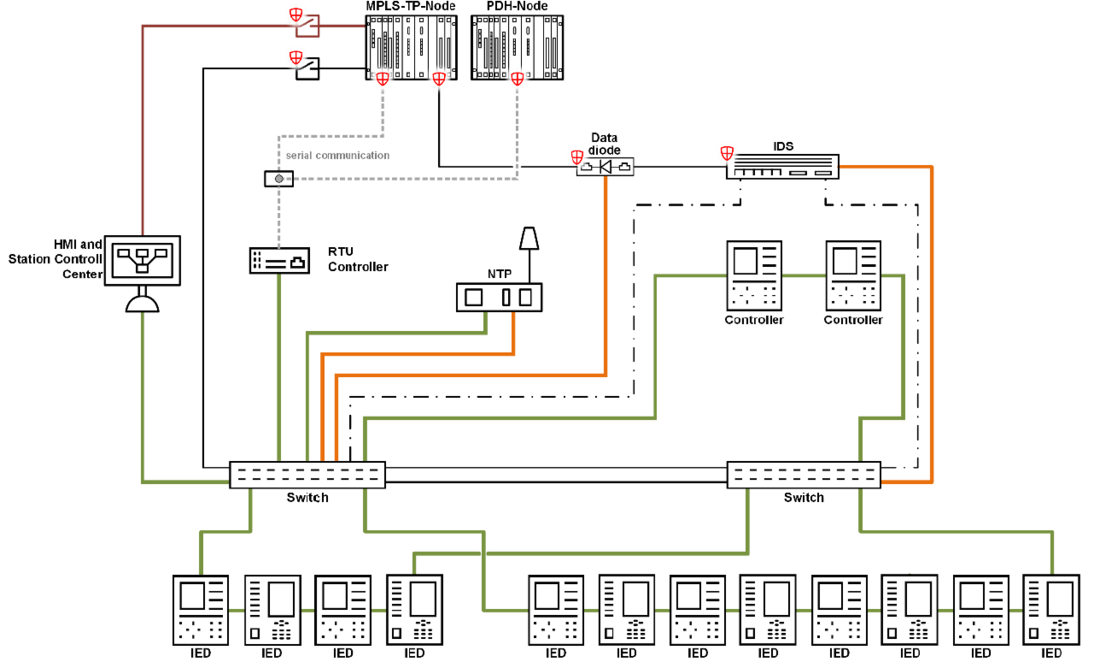
Figure 1 - Substation communication network; CKW specification US2010
Figure 1 shows the older layout of a system with IEC 61850 at CKW. In these systems, there was little segmentation and functional separation. Data diodes and IDS were also not used at the beginning. These have recently been retrofitted. In the new systems, as shown in Figure 2, the network was heavily segmented using VLAN (shown with different colors in Figure 2), process and support networks were physically separated and additional functions such as RBAC (Role-Based Access Control) were introduced on all devices or firewalls were used.
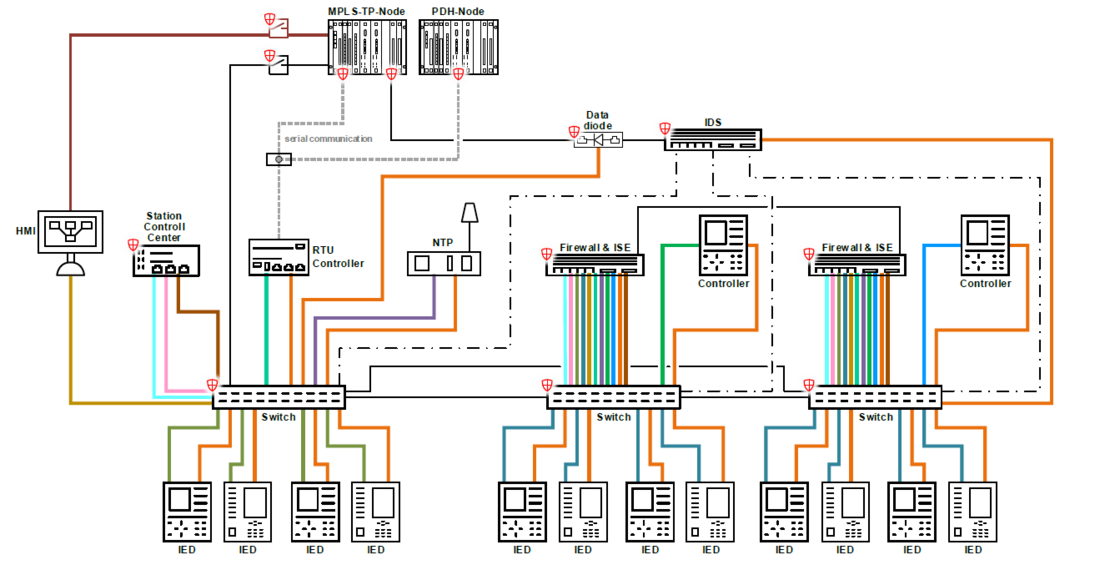
Figure 2 - Substation communication network; CKW specification US2020 with enhanced security
The differential protection connections between substations are currently implemented via interfaces according to IEEE C37.94. In some cases, with dedicated optical fibers and binary contact transmissions for distance protection. A schematic representation of this can be found in the following Figure 3.
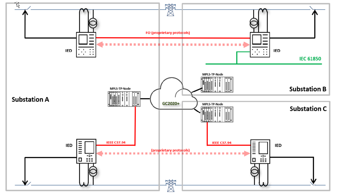
Figure 3 - Line protection using direct fiber optic connections or channel emulation over MPLS-TP and IEEE C34.94 interfaces
From CKW's point of view, the use of SV within the station is not yet a pressing issue, as the necessary hardware is not yet reduced, but rather increased. In addition, the complexity and requirements of the networks in terms of reliability and availability are increasing and testing is becoming more time-consuming. The use of powerful and expensive protection devices as pure MU or PIU (Process Interface Units) currently makes little sense.
In contrast, inter-substation SV streams offer an advantage as they can reduce hardware costs and dependencies. Proof of functionality with devices from one manufacturer has already been provided in a CIGRE paper [5]. The extension of the tests with other manufacturers is now intended to prove the interoperability of the devices with SV according IEC 61850-9-2 standard. If the tests are successful in the field, CKW envisages the use of protective connections as shown in Figure 4 for future specification:
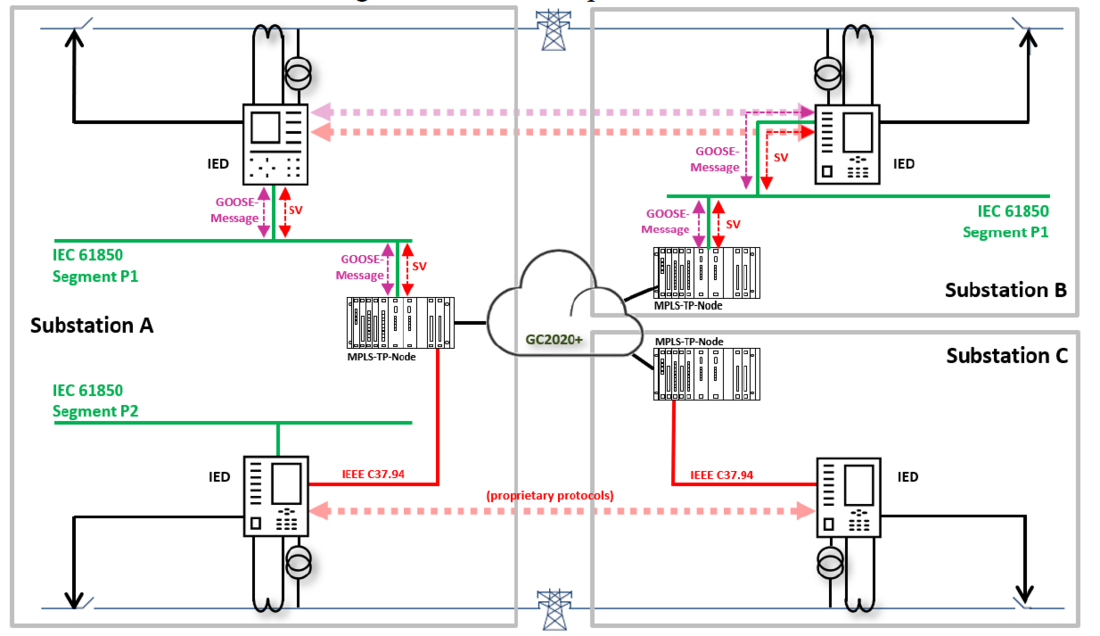
Figure 4 - New concept of Line differential protection using SV and different relay vendors ; together with existing applications using channel emulation and IEEE C37.94
Substation A is upgraded to the latest specification and Substation B has already been converted and is prepared for processing SV streams. Station C is equipped with older technology and cannot process SV streams. In this constellation, the differential protection between Substation A and B can be realized with the approach of using SV streams. It is not necessary to replace the device in Substation B. The differential protection in Substation C must either be replaced or a compatible device must be used in Substation A so that the existing interface can continue to be used. In some cases, devices of different device generations from the same manufacturer can be combined.
2.2. OT-WAN network structure (MPLS-TP) overview
CKW relied on PDH/SDH networks for its process-related OT-WAN network (OT: Operational Technology). Due to the age of this infrastructure, the entire OT-WAN has been replaced by a modern MPLS-TP network in recent years.
All data traffic between the communication nodes is realized via MPLS-TP as an OT-WAN. The entire communication network has time, phase and frequency synchronization and is operated with three different PTP sources. The entire network is implemented according to the meshed approach, whereby the paths have defined routes, as it is common with MPLS-TP. The individual paths are encrypted with keys from quantum generators. This algorithm can hardly be decrypted with the means available today and will continue to offer security even with the emerging availability of quantum computers. Differential protection data is transmitted on the MPLS-TP network via channel emulation and IEEE C37.94 and protection signal transmissions. These connections are switched redundantly. Failure of one connection does not lead to a service interruption (hitless redundancy). The connections between the gateways in the substations and the front ends in the SCADA are also transmitted with the IEC 60870-5-101/104 protocol.
For future applications with process bus in accordance with IEC 61850-9-2, the OT-WAN serves as a PTP time source for all possible applications. This enables the transmission of SV streams within systems or across system boundaries. In future, it will also no longer be possible to transmit protection signals using binary signals, but instead directly to neighboring stations via the WAN using GOOSE messages.
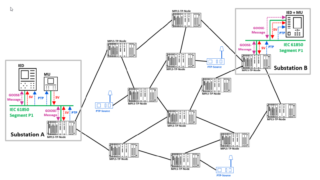
Figure 5 - CKW MPLS-TP network with 70 Nodes and three PTP sources; future substation with SV
In addition to the protection-related data, there are other use cases for which the OT-WAN is utilized. These include remote access to the substations to ensure service and support. Access monitoring and building monitoring systems are also made available via this network. The telephony in the plants is also operated via this system to ensure availability in the event of large-scale disruptions to the energy supply. All systems are equipped with a UPS to ensure that this is possible. The OT-WAN is therefore used exclusively for the operation of the OT systems. There are no data transmissions for third parties, not even for CKW's internal business needs for IT systems.
3. Multi-vendor Line differential protection
3.1 Typical line differential protection concepts
The principle for line differential protection is simple. If the sum of currents flowing into the line terminals exceeds a threshold value, an internal fault is present and the relays at all line ends are expected to trip the circuit breakers instantaneously. The threshold value can be calculated by different vendor specific characteristics (multi-slope, alpha-plane, adaptive methods) to stabilize for different physical effects (e.g. line charging, inrush currents).
Most important for differential protection is a precise current signal alignment from all line terminals. The following methods are typically applied in IED (Intelligent Electronic Device):
| Ping-pong method | Global synchronization methods | |
|---|---|---|
| Principle | Time tags or ID's exchanged in telegrams to estimate the channel roundtrip time | 1PPS (derived from GNSS) or PTP used for global time stamping of exchanged telegrams |
| Sampling | Asynchronous | asynchronous or synchronous |
| Communication channel delays (Tx, Rx) | Symmetrical transmission delays required | Difference in channel delays acceptable |
The telegram payload data is vendor specific and optimized for the alignment method, channel bandwidth and additional functions. For line differential protection typically only current phasors (magnitude and angle) are transmitted beside time stamps, ID’s and additional binary signals (for e.g. intertripping).
A line differential compatibility is not given today, because of the differences in the used vendor specific telegrams, payload and signal processing. The differential relays at all line ends must be from the same vendor. Some vendors even require the same relay type and firmware version at the line ends. The benefit for the customer of such a solution is a type tested protection optimized for low bandwidth communication channels.
3.2. New line differential protection approach
To overcome the drawbacks of using a single relay vendor and proprietary protection hardware and/or telegrams, a standardized data format is required. Up to now, there is not such a standardized line differential protection protocol available, and no standardization activities are driven by IEC or IEEE PSRC.
To obtain an interoperability between different relay vendors the IEC 61850 communication networks and systems for power utility automation and the SV standardized in part 9-2 are particularly suitable for fast analog signal exchange [6].
This communication standard series provides the format for:
- Exchange of sampled current and voltage signals (SV and process bus): part 9-2
- Exchange of binary signals (GOOSE): part 8-1
Two concepts for line differential protection using SV are shown in Figure 5. Depending on the IED’s functionality an SV stream of the line feeder can be provided on process bus for local protection and for the remote end line protection relay (Figure 5, Substation B). This function can also be separated and a SAMU or MU may provide the SV stream for the local and remote protection devices (Figure 5, Substation A).
Each IED at the line terminals evaluates the SV’s from local and remote end and performs its vendor specific :
- digital signal processing including filtering,
- differential and restraining current calculation,
- additional stabilization methods (e.g. in-zone transformer inrush, CT saturation),
- comparison with specific tripping characteristics.
Because different relay vendors are applied for the line protection, the decision for tripping will differ (at least in timing) for both line ends. Therefore, an intertrip-signal is needed to secure that both CB are operated at both line ends. A GOOSE signal can be used for this purpose. Additional status information (e.g. local test or blocking signals) shall be agreed and signaled by GOOSE between the IED at the line ends. Using multi-vendors for the line differential application with intertrip-signal will enhance the protection reliability due to hardware and algorithm diversity and redundancy.
For the general case of using different hardware for the signal acquisition (MU or IED) the SV streams will differ slightly for the d.c. signal components or higher frequency responses. The frequency response of a SAMU is standardized in IEC 61869-13. Lab type tests are recommended before using a pair of different vendors for line differential applications [4].
Most important is a reliable time synchronization of the measurements at both line ends. Small time differences will lead to apparent differential currents, which needs to be minimized. Local synchronization at each substation using GNSS (Global Navigation Satellite Systems) is possible but may be impacted by atmospheric influences and even more critical by signal jamming and/or spoofing. Therefore, a synchronization signal distribution in the whole WAN is a more secure option. The clock signal will be transmitted in all substations using PTP.
The maximum time delay expected by the MU from the remote line ends needs to be specified for the SV clients according to IEC 61850 (LPHD.MaxDI). Typically, the client’s internal buffer (e.g. 3.5 ms) will limit the max. possible delays and communication path length but also adds this delay to the protection operation.

4. Engineering process and testing at CKW
4.1 IEC 61850 engineering and device configuration process
An IEC 61850 engineering of a substation relies on different types of software tools. First are the configuration tools for the used protection devices which are a part of the deliverables from the different vendors. The second more important part for a proper engineering process is the so-called IEC 61850 engineering tool. This type of software is available from different vendors and need to be interoperable with every IEC 61850 certified protection device independent from the vendor. The engineering tool is responsible for the publisher and subscriber mechanism of SV and GOOSE and possible higher-level configuration such as time synchronization as well as SCADA. In addition are cyber security relevant settings in the authority of the engineering tool such as multicast MAC address as well as VLAN tag handling of SV and GOOSE. For the inter-substation communication, a proxy gateway approach according to IEC 61850-90-1 is used. The gateway IED is integrated in the MPLS-TP communication equipment and support beside the inter-substation communication of SV and GOOSE also the PTP gateway function to convert the ITU-T G.8275.1 PTP telecom profile to IEC 61850-9-3 PTP utility profile as well as SNTP server and full MMS support to be integrated into a SCADA system.
To be able to engineer a vendor mixed substation setup with inter-substation communication support, the following features need to be supported by the used IEC 61850 engineering and protection device configuration tools:
- Capability to import and export SCD (Substation Configuration Description) files
- Capability to import and export IID (Instantiated IED Description) files
- Capability to import ICD (IED Capability Description) files
The full IEC 61850 engineering process explained in Figure 6 was done using the IET600 from Hitachi Energy. The Substation A contained a SAM600 MU and a RED670 differential protection device which was configured with PCM600 from Hitachi Energy. The TEGO1 inter-substation IEC 61850 gateway [3] which is a part of the Hitachi Energy FOX615 communication platform was configured using the TET (TEGO1 engineering tool). In Substation B, a SIPROTEC 5 7SL86 line differential protection device including a MU from Siemens which was configured by DIGSI 5. The gateway device in Substation B was also a TEGO1 device.
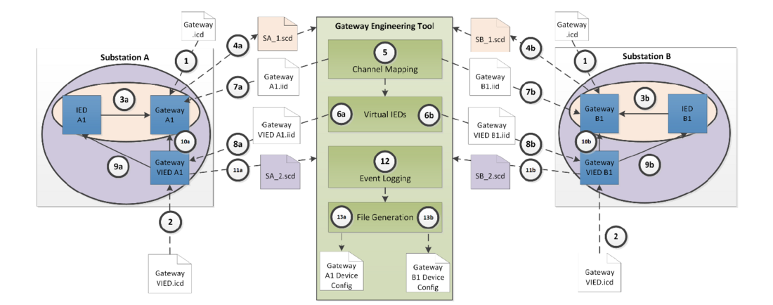
Figure 6 - Step by step IEC 61850 inter-substation engineering
The IEC 61850 standard was originally written from a substation perspective, therefore inter-substation communication was not foreseen. Engineering tools are also handling just one substation at a time. This brings additional complexity into the IEC 61850 engineering process and make the process shown in Figure 6 necessary. The Gateway Engineering Tool handles the data which are exchanged between the two or multiple substations where each virtual Gateway (Gateway VIED) represents the publisher of the remote IEC 61850 data which are transmitters between the substations.
Following the different engineering steps from Figure 6 described with more details:
- Import of the Gateways ICD file to the IEC 61850 engineering tool
- Import of the virtual Gateway ICD file to the IEC 61850 engineering tool
- Subscribe the relevant GOOSE and SV message from the IED to the Gateway
- Substation A: The Gateway A subscribe to the SV stream from the SAM600 and the GOOSE message from the RED670
- Substation B: The Gateway B subscribe to the SV stream and GOOSE message from the 7SL86
- Export the SCD file from both substations
- Import both SCD files to the Gateway engineering tool and define the connection (MPLS-TP) between the two substation
- Define the GOOSE and SV data which are send to the remote side (represented in the remote VIED instance)
- Import the IID file from the Gateway created from the Gateway engineering tool in the IEC 61850 engineering tool (on both substations)
- Import the VIED IID file from the VIED Gateway created from the Gateway engineering tool in the IEC 61850 engineering tool (on both substations)
- Subscribe the relevant GOOSE and SV message from the VIED Gateway to the IED
- Substation A: The RED670 subscribe to the SV stream and the GOOSE message from the VIED Gateway (represents the data from the remote Gateway IED which origins from the 7SL86)
- Substation B: The 7SL86 subscribe to the SV stream and the GOOSE message from the VIED Gateway (represents the data from the remote Gateway IED which origins from the RED670 and SAM600)
- The local Gateway IED subscribe to the data from the VIED Gateway for local event logging capabilities in the Gateway IED’s.
- Export the SCD file from both substations
- Import both SCD files to the Gateway engineering tool and configure the event logger of the both Gateway IED’s
- Generate the configuration file for the Gateway IED and load it to the device
4.2. Relay testing
After few web meetings to discuss the relay settings using the above described workflow, the lab tests at CKW was prepared in May 2023. The real substation communication system of CKW GC2020+ was used to simulate different communication path length with realistic network load. Figure 7 shows the simplified test setup.
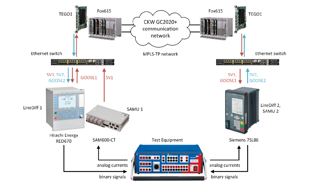
Figure 7 - Simplified test setup at CKW
For time synchronization of the IED’s and MU’s the IEC 61850-9-3 PTP profile was applied. To separate the test from the operational network traffic VLAN tags were used for:
- PTP
- Sampled values
- GOOSE messages
The secondary currents have been applied to the IED and MU using a relay test equipment (Omicron CMC 356). IED’s have been configured to monitor the PTP state, SV currents and differential currents via HMI and/or web interface. Remote access to the IED’s allowed a comfortable test preparation of 6 persons involved, while the test devices were connected to the switches in the telecommunication room (Figure 8).
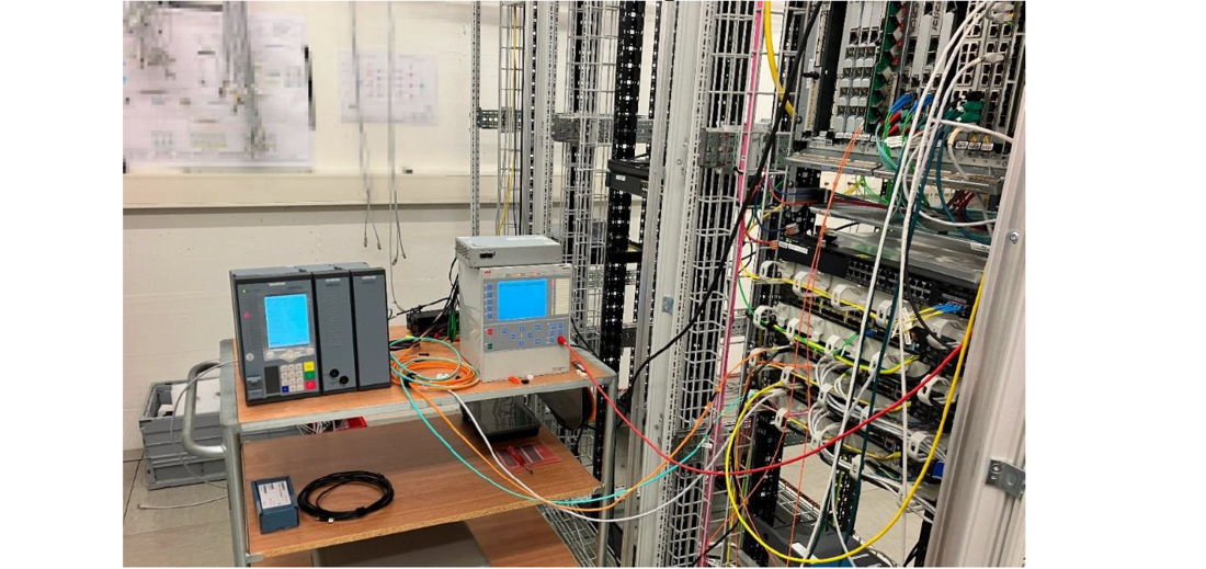
Figure 8 - Line differential protection test setup using two relay vendors at CKW in May 2023
5. Results of the lab test
The test execution was planned for 2 days at CKW, Lucerne. On the first day we set up the devices and focused on the PTP time synchronization and SV exchange. On the second day we tested different path length up to 33 hops over MPLS-TP-devices and approximately 250 km fiber and applied secondary currents with the relay test equipment (Figure 9).
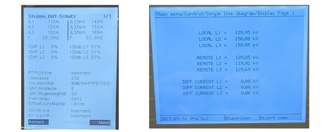
Figure 9 - HMI screenshots during the line differential test with SV from remote line end
From our knowledge this was one of the first tests using multi-vendor, inter-substation line differential protection using IEC 61850, GOOSE and SV at a real customer network. Obviously, some challenges have been faced during the lab testing. The lessons learned are outlined afterwards:
PTP time synchronization
Synchronization via PTP with the various existing profiles caused difficulties. The switch and the different protection devices all expected different PTP-profiles or versions of it. CKW expects that one profile with latest version will prevail or that all profiles and versions will be supported by the various manufacturers.
The test was finally successful with the use of IEC 61850-9-3:2016.
Max. MU delay time
Using an internal buffer size of 3.5 ms, we tested successful the line differential protection up to a communication channel length of about 250 km. The max. length depends mainly on the difference in MU delays, processing delays in MPLS-TP routers but also on the fiber optic delays [5]. Longer communication path led to blocked line differential protection.
VLAN segregation
We used separate VLAN for the GOOSE messages, the SV streams and the management network. CKW's approach with the strong segmentation of the networks was also tested in this way.
IED functionalities
Although the tests were successful, additional IED functions have been specified and are beneficial for the end users for such applications – e.g. enhanced channel monitoring features (delays, availability) which are part of the end to end supervision of IEC 61850.
Customer responsibility for complete protection
The flexibility of using different vendors at the line ends puts more responsibility to the customer for the whole line protection. This can be secured using such laboratory tests as presented in the paper.
The results show that the promise of IEC 61850 to be able to run multi-vendor setups for differential protection are possible and ready to use. The long used proprietary communication for differential protection between two substation and therefore the use of the same devices, sometimes even the same firmware version is now obsolete. Using the standardized communication based on IEC 61850 make local substation as well as inter-substation communication more flexible and future prove. Handling different tools from different vendors increase the need of having feature rich importing and exporting features of these. The minimum need of import and export of files is seen in chapter 4.1.
Along with the GOOSE and SV interop test done with this lab test, the interoperability of PTP between different vendors as well as the approach of using a network clock to synchronize each substation from centralized PTP Grandmasters in the communication network as seen in Figure 5 is proven.
A major takeaway of the whole activity is that the technology is ready to provide full IEC 61850 based substation with the capability to interconnect them, but the need of completely different know how for vendors as well as for operators is a challenge. A fully digital substations need much more network- as well as IT-skills than the today used conventional approach. Know how build up and the capability to test and verify in a lab are key factors to be successful in the digital journey.
6. Outlook on future works
After the successful lab test of IEC 61850 based differential protection with GOOSE and SV over substation boundaries in a multi-vendor setup, a field test of the same setup is planned for 2024. This several month-long field test should prove that this novel approach is ready to be used in a wide scale and making new protection scheme possible.
In addition to the differential protection approach, the SV stream can also be used for new wide area protection setups which need to be proven before real use.
Also, for CPC (Centralized Protection and Control) systems the use of SV from the remote line end(s) will allow the implementation of line differential protection without the need for dedicated protection communication interfaces (hardware modules).
After a successful test in the field, CKW will adopt the approach shown here in the specifications and demand this functionality in future tenders. Although distance protection devices are predominantly used today, the current technology allows differential protection to be used across the board in the high-voltage grid with minimal additional costs.
CKW will clearly specify how segmentation is carried out, which PTP profile is used and what signal propagation times can be expected. If necessary, further interoperability tests with devices from other manufacturers as part of this process will be carried out.
7. Conclusion
The test successfully showed that it is possible to operate a stable differential protection system in the laboratory using devices from different manufacturers.
There is still work to be done before this approach is fully mature. The manufacturers must prepare their functions in such a way that line differential protection can be supplied with SV streams from other line ends. The desired segmentation has not yet been fully tested and documented. CKW needs to carry out further tests with the manufacturers. The use of a standardized time source with the Power Utility Profile for PTP will be able to replace the local GNSS clocks. To do this, all devices used in the network must be able to handle this profile. The presented results in this paper are promising for upcoming field tests at CKW in 2024.
References
- IEC 61869-13: Instrument transformers – Part 13: Stand-alone merging unit (SAMU). Geneva. Feb. 2021
- IEC 61850-9-2: Communication networks and systems for power utility automation – Part 9-2: Specific communication service mapping (SCSM) – Sampled values over ISO/IEC 8802-3. Geneva. Sep. 2011
- Hitachi Energy: FOX615 TEGO1 user manual. Aug. 2023
- Siemens: SIPROTEC 5 Process bus – Manual, V9.60. Aug. 2023
- Bächli, R.; Kranich, M.; Borisavljevic, M.; Frei, A.; Mattmann, S.; Gosteli, J.: Using IEC 61850 differential protection over Multiprotocol Label Switching – Transport Profile (MPLS-TP) wide area networks. Paper D2-PS3-907.CIGRE Session 48. Paris, 2020
- Blumschein, J.; Kerger, T.; Matussek, R.: Interoperability of Line Differential Protection. DPSP 2020