A New MMC-Based Topology with Integrated Zig-Zag Transformer for Elimination of Discrete Arm Inductors
Authors
Beicheng YUAN, Noah J. B. HOSEIN, Peter W. LEHN - University of Toronto, Canada

Summary
The Modular Multilevel Converter (MMC) is a versatile AC/DC converter topology used in HVDC applications and has unique advantages which position it to become a prominent technology in many emerging applications as well. However, high component cost has been a major constraint in traditional MMC designs focusing research efforts on the development of more cost-effective solutions. In this paper, a new MMC-based topology termed the Zig-Zag Modular Multilevel Converter (ZMC) is proposed which eliminates the cost of discrete arm inductors. Instead of interfacing with the AC grid through an external transformer, the ZMC directly integrates a Zig-Zag transformer into its phase legs, replacing expensive discrete arm inductors with the leakage inductance of the integrated transformer windings. The unique Zig-Zag winding configuration offers flux cancellation of the DC current to minimize transformer core size and cost. In addition to presenting the new topology, this paper also outlines the operating principles and control scheme for the ZMC. It is mathematically demonstrated that the ZMC decouples the dynamics of the DC and AC power systems and has submodule capacitance sizing criteria equal to that of the traditional MMC. Finally, to validate the feasibility of the proposed topology and operation, simulation and experimental results are presented for a test system and laboratory-scale prototype.
Keywords
Modular Multilevel Converter, Arm Inductors, Zig-Zag Transformer, HVDC, MVDC, VSC, DC Flux Cancellation1. Introduction
Over the past two decades, the Modular Multilevel Converter (MMC) [1] has become an established technology in modern HVDC systems and has gained interest for emerging applications such as MVDC distribution, industrial motor drives and electric vehicle charging infrastructure. In comparison with Line Commutated Converter (LCC) based topologies, the MMC has advantages such as independent control of active and reactive power, reduced filtering requirements, and grid-forming capabilities [2]. Furthermore, the unique modular structure of the MMC allows it to scale to high voltages while also reducing the harmonic content of the AC voltages compared with other voltage source converter (VSC) topologies.
In many applications, the MMC is the most expensive part of the entire system. This has motivated research into the development of modified MMC designs which are more economical. While the submodule capacitors continue to be the most expensive component, the arm reactors also constitute a significant expense in traditional MMCs. For proper functionality, the arm reactors must be sized adequately in order to prevent high-frequency circulating currents between legs and to limit the rate of increase of DC side fault currents. However, since the arm reactors must not saturate under the DC flux produced by the string currents, they are usually of air-core type construction, making them bulky and expensive.
In the traditional MMC, the converter interfaces with the AC grid by connecting the AC terminals of the converter to an external line frequency transformer as shown in Figure 1(a). However, direct integration of the transformer into the MMC legs provides an opportunity to eliminate the cost of discrete arm reactors by instead utilizing the transformer leakage inductance [3]. This concept was first explored in [4] where the converter side transformer windings are placed directly in series with the submodule strings. However, a major problem in [4] is that the DC component of the string currents generate a DC flux in the transformer requiring significantly larger and more expensive transformer cores to prevent magnetic saturation.
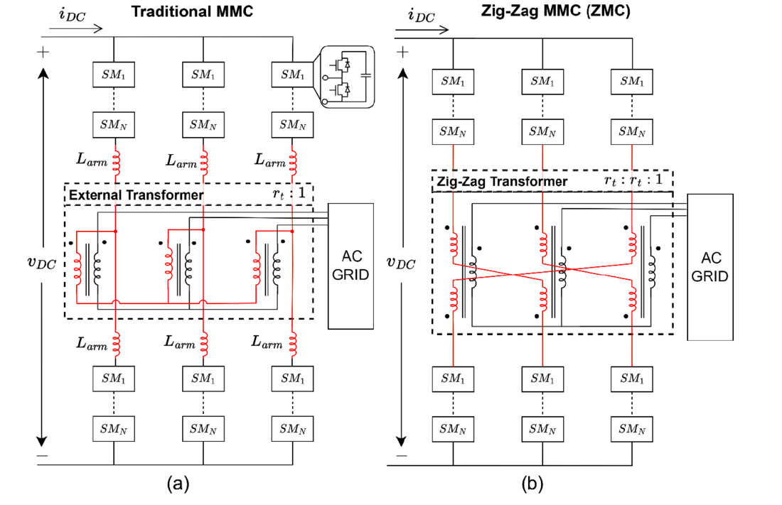
Figure 1 - (a) Circuit topology of the traditional MMC. (b) Proposed circuit topology of the ZMC.
To mitigate the generation of DC flux in the transformer when it is directly integrated into the MMC, the topology proposed in [5] utilizes three-winding transformers with oppositely wound secondary and tertiary terminals in each arm of a converter phase leg. The effective coupling between the upper and lower arm cancels flux generated by the DC component of the string current. With the integrated transformer, the leakage inductances of the converter-side windings serve as the arm reactances, eliminating the need for discrete arm inductors. Winding arrangements leveraging DC flux cancellation have also found application in multi-port MMC topologies as described in [6].
While the topology of [5] achieves DC flux cancellation by introducing magnetic coupling between arms of the same phase leg, DC flux cancellation can also be realized by coupling arms in different phase legs. Such a configuration can be achieved through the use of a Zig-Zag transformer [7]. In this topology, the oppositely wound secondary and tertiary terminals of the three-winding transformer are connected to the top and bottom arms of different MMC phase legs as shown in Figure 1(b). However, since the DC component of the string current is equal in each leg, the oppositely wound configuration effectively cancels the DC flux, despite the transformer coupling across different legs. As detailed later, other important properties also result from this arrangement such as decoupling of the AC and DC grids.
The purpose of this paper is to present this new MMC topology based on the direct integration of the Zig-Zag transformer termed the Zig-Zag MMC (ZMC). This paper will explore the new topology and describe the fundamental principles governing its operation. A simplified control scheme is presented in addition to a power ripple analysis of the submodule strings. Finally, a simulation model and laboratory-scale prototype are presented to verify the proposed topology and operation.
2. Circuit topology
The proposed circuit topology of the ZMC is shown in Figure 1(b). Like the MMC, each of the three phase legs of the ZMC is constructed from strings of half-bridge voltage source submodules (VSMs) connected in series. More specifically, each of the three phase legs contains an upper and lower VSM string each with ? VSMs. In a traditional MMC the upper and lower string are each connected in series with discrete arm inductors ???? and the midpoint created between the inductors is connected to an external transformer. However, in the ZMC a three-winding Zig-Zag transformer is instead connected directly in series with the VSM strings, replacing the external transformer and discrete arm inductors.
Altogether, each phase leg comprises the series connection of an upper VSM string, two windings of the Zig-Zag transformer, and a lower VSM string. As shown in Figure 1(b), the converter side transformer windings each have a leakage inductance ???. Thus, each winding can be effectively represented as an ideal transformer with a series inductance ???. Based on the sizing criteria provided in the CIGRE B4 DC Test System [8], ??? can be of similar magnitude or even slightly larger than the discrete arm inductance used in traditional MMCs. Additionally, it should be noted that to simplify the analysis in this paper, the grid-side leakage inductance and transformer magnetizing inductance have been neglected.
A detailed view of the ZMC’s topology and Zig-Zag transformer connection is provided in Figure 2. The Zig-Zag transformer is constructed out of three phase legs each with three windings on each leg. The primary winding has ?? turns and is connected to the AC grid. More specifically, the positive terminal is connected to a phase of the AC grid and the negative terminal is connected to the transformer wye point. In contrast, the secondary and tertiary windings of each leg have ?? turns and are connected directly in series with VSM strings of the ZMC. More specifically, the positive terminal of the secondary winding connects to an upper VSM string, and the positive terminal of the tertiary winding connects to a lower VSM string (note the dotting in Figure 2). The negative terminals of these windings are configured such that they connect a secondary and tertiary winding in series. However, this is performed such that the secondary and tertiary winding are from different transformer legs, creating the distinctive “Zig-Zag” pattern seen in Figure 2.
For example, the secondary winding which is magnetically coupled to phase A of the AC grid is connected in series with the tertiary winding which is magnetically coupled to phase B of the AC grid. This winding arrangement enables DC flux cancellation since any current common to all of the VSM strings will generate opposing magnetomotive forces in the secondary and tertiary winding of each transformer leg.
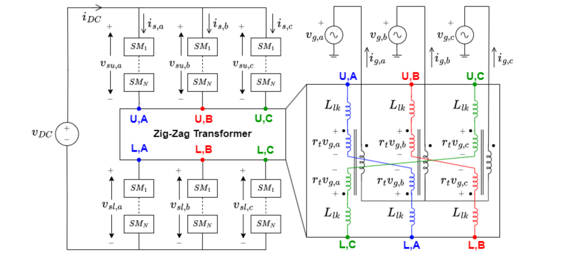
Figure 2 - Detailed circuit topology of the ZMC and Zig-Zag transformer
3. Principles of operation
Operation of the traditional MMC is based on the concept of modulating the upper and lower arms of the converter to shape the midpoint voltage into a reference AC waveform. Simultaneously, the total voltage across both the upper and lower arms is controlled to match the DC-link voltage and supress currents that can circulate between phase legs.
In contrast, the ZMC strings have no midpoint voltage and the Zig-Zag transformer directly injects a voltage into the phase legs. Furthermore, the Zig-Zag transformer couples the string currents with the AC grid currents allowing control through modulation of the VSM strings.
To understand how the strings must be modulated, it is useful to derive a simplified equivalent circuit model of the converter. The first step in this derivation is to reflect the grid voltages into the converter phase legs. Using Figure 2, it is easy to see that the net voltage injected by the Zig-Zag transformer into converter leg x ???,? is equal to:
(1)
where ??,? is the AC grid voltage of phase x and ??=??/?? is the transformer turns ratio.
Additionally, the relationships between the string currents and grid currents created by the Zig-Zag transformer coupling can derived using the transformer element constraints:
(2)
where ??,? is the phase x grid current and ??,? is the string current in phase leg x of the ZMC.
These relationships highlight the fact that the grid current is fully defined by the individual string currents. Thus, all analysis can be formulated in terms of the string currents.
Finally, since there is no midpoint connection, the upper and lower VSM strings are actually just in series and any voltage difference between them has no effect. Thus, instead of considering the strings of phase x as two individual voltages ???,? and ???,?, they can be effectively replaced by a single variable representing their sum:
(3)
Utilizing these simplifications, the ZMC can effectively be reduced to the equivalent circuit shown in Figure 3. Here the VSM strings of each phase leg are represented as a single controllable voltage source and the grid voltage reflected through the Zig-Zag transformer is modelled as an independent AC source.
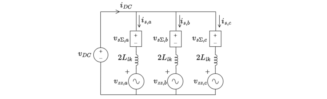
Figure 3 - Simplified equivalent circuit of the ZMC
From Figure 3, it can be seen that ZMC operation must be designed to modulate the VSM strings to inject a voltage in series with the grid voltage reflected through the Zig-Zag transformer. The injected voltage must be designed to control the string currents such that the AC and DC grids remain decoupled. This can be achieved by circulating the reflected AC grid current between phase legs while conducting the common DC current through all three converter legs simultaneously. To illustrate how the AC and DC circuits can be completely decoupled, the equivalent circuit of Figure 3 can be transformed into the αβ0-frame using the Clarke transformation.
To start, KVL is applied to the three loops formed by each phase leg and the DC link as shown in Figure 3:
(4)
(5)
(6)
By applying the amplitude invariant Clarke transformation [9], the dynamic equations can be transformed into the αβ0-frame:
(7)
(8)
(9)
Now using Eq. (1), ???,0 can be calculated:
(10)
Using this relationship and the fact that from KCL ???=??+??+??=3??0, Eq. (9) effectively reduces to:
(11)
This relation captures the DC dynamics of the converter and can be represented as the equivalent circuit shown on the left in Figure 4. Similarly, Eq. (7) and Eq. (8) capture the AC dynamics and are also shown as equivalent circuits in Figure 4. Notice that the AC and DC circuits are completely separate. The reflected AC grid voltages ???,? and ???,β interact with the VSM string’s α and β components and the DC grid interacts with the common-mode (0) component. This is because only the α and β components circulate between the phase legs and couple with the transformer windings whereas the common-mode component experiences flux-cancellation and therefore does not couple with the AC grid through the transformer. Thus, the VSM strings are modulated so that their common-mode component acts as a controlled DC source which regulates the DC grid current. Furthermore, the α and β components of the string voltages are grid-frequency AC quantities with controllable phase and magnitude for regulation of the AC grid currents. A more detailed discussion of how this control is implemented is provided in the next section.
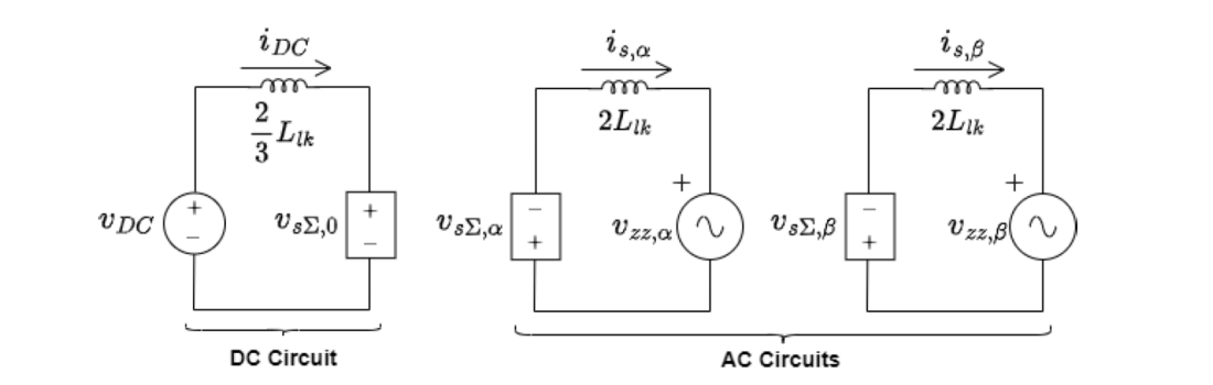
Figure 4 - Equivalent circuits of the ZMC in the αβ0-frame
4. Control Scheme
To regulate the power exchanged between the AC and DC grids, the ZMC must be able to control both the AC and DC grid currents. In this paper, it is assumed that both the AC and DC network voltages are held stiff by their respective grids, permitting the use of grid-following control. A simplified block diagram of the proposed control scheme is shown in Figure 5, below. Note that the dq0-frame is utilized in Figure 5 instead of the αβ0-frame used to derive the equivalent circuits of Figure 4. However, the analysis presented earlier in the αβ0-frame extends to the dq0-frame with the only major difference being that AC quantities of the stationary αβ-frame are converted to equivalent DC quantities in the rotating dq-frame.
In Figure 5, a PLL locks onto the reflected Zig-Zag voltages which are calculated from the measured AC grid voltages at the PCC to generate the reference angle for the dq0-frame. The reference angle theta is then used to transform the measured string currents ??,??? into the dq0-frame using the Park Transform.
To control the AC grid currents, the d and q-axis string currents are regulated using proportional-integral (PI) controllers. However, only utilizing a simple PI controller is insufficient to reject disturbances in the ZMC. This is because the AC to DC power conversion process results in a second harmonic voltage ripple appearing on the submodule capacitors. In the traditional MMC, the AC midpoint voltage is unaffected by the second harmonic ripple, preventing any disturbance to the AC grid currents. However, in the ZMC, this ripple couples with the AC grid and induces a negative sequence second harmonic current. In the dq-frame, this negative sequence second harmonic is seen as a third harmonic which cannot be perfectly supressed with only a PI controller. Thus, to eliminate this, a third harmonic resonant component R is added to the ??,? and ??,? controllers [10]. Therefore, in Figure 5 a PIR controller takes the dq-frame current references and
and measurements ??,? and ??,? to generate the VSM string reference voltages ??,? and ??,?.
By choosing the dq current references, the net power exchanged with the AC grid is set. Power balance of the converter requires this energy to come from the DC grid and since it is assumed that the DC grid voltage is fixed by the network, this effectively imposes a steady-state value for the DC current ???. To control the transient dynamics and stabilize ???, a proportional-resonant (PR) controller [11] is implemented for the common-mode (0) string current. Recall that the DC current is simply the common-mode string current multiplied by three. In the control scheme of Figure 5, the reference for the PR controller is computed from the d-axis current reference based on ideal power balance (assuming lossless conversion). The measured common-mode string current ??,0 and computed
are fed into the PR controller which outputs the common-mode VSM string reference voltage ??,0. The resonant component is tuned to the third harmonic for suppression of DC current ripple arising from coupling between the second harmonic VSM capacitor ripple and the fundamental frequency VSM string modulation. Note that an integrator is not used on the common-mode controller as this will result in zero-error tracking of the reference which is calculated assuming lossless conversion. However, a small tracking error is necessary to account for power imbalance resulting from converter losses.
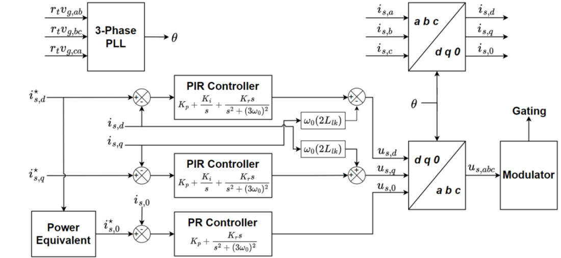
Figure 5 - Simplified block diagram of the ZMC control scheme
In total, there are three controllers in Figure 5, one for each degree of freedom (d, q, and 0). The ZMC does not require any additional controllers to suppress circulating currents as compared with the traditional MMC since there are no extra degrees of freedom. The VSM string reference voltages ??,??0 output by these controllers are converted back into the abc-frame using the inverse Park transform. The resulting abc-frame reference voltages ??,??? are then sent to the modulator to generate the gating signals for the individual VSM switches. Any modulation scheme used for the traditional MMC can be used for the ZMC such as direct modulation with level-shifted carriers (LSC) and a VSM sorting algorithm [2].
5. Power ripple analysis
Similar to the MMC, AC/DC power conversion in the ZMC is realized within the submodule strings. As discussed in prior sections, this is achieved by gating each string with both a DC and AC component. The DC current flowing from the DC grid interacts with the DC component of the string voltage to exchange net power. Similarly, the AC current from the transformer interacts with the AC component of the string voltage to exchange net power. Steady state operation requires that these two powers are balanced in order to maintain a constant submodule capacitor voltage. This is referred to as power balance of the submodule strings.
In addition to net energy exchange, harmonic power ripples also appear on the submodule capacitors as a result of the conversion process. Typically, a first harmonic component appears as a result of cross-interactions between the AC and DC voltages/currents. Furthermore, a second harmonic ripple also exists due to the single-phase AC power conversion in the strings. Quantifying these ripples is necessary for proper sizing of the submodule capacitance.
The following derivation will mathematically demonstrate AC/DC power balance in the ZMC and show that the power ripple calculations result in the same sizing criteria for the submodule capacitance as an equivalently rated MMC.
If switching frequency harmonics are neglected, from inspection of Figure 4 it is clear that in steady state operation the common-mode string voltage ??Σ,0 is equal to the DC grid voltage ??? and the ??Σ,? and ??Σ,? components of the string voltage will be purely grid-frequency AC quantities. Applying the inverse amplitude-invariant Clarke transformation to these voltages, the general form of the upper and lower VSM string voltages is found to be:
(12)
where ??? is the steady state DC grid voltage, ??? is the peak AC string voltage amplitude, ??? is the DC grid current, ??? is the peak AC string current, and ? is the lagging phase of the current with respect to the string voltage.
Assuming lossless conversion and taking the product of the voltage and current to calculate the instantaneous string powers yields:
(13)
This expression shows that the string powers contain constants as well as first and second harmonic components. The constant terms and
represent the net power exchanged with the DC and AC grid, respectively. Since these powers are equal in steady state operation, they cancel out in Eq. (13) demonstrating net power balance in the string.
Now to compare the amplitude of the harmonic power ripples with the traditional MMC, it will be convenient to define the total power ? transferred between the DC grid and each phase of the AC grid as well as the modulation index as follows:
(14)
where the modulation index takes on a value between 0 and 1. Using these definitions, Eq. (13) can be rewritten as:
(15)
In comparison, for the traditional MMC the upper and lower string power expressions are:
(16)
(17)
Thus, although the phase of the first harmonic ripple of the lower strings may be different in the ZMC and MMC, the power ripple amplitudes are the same. Therefore, the ZMC and MMC have identical submodule capacitance sizing constraints.

6. Simulation results
To validate the proposed topology and operation of the ZMC, a test system was designed and simulated. The parameters of the test system are listed in Table 1. The simulated ZMC has a rated power of 9 MVA and interfaces a 20 kV DC grid with a 12.47 kV AC grid. The converter is operating with the proposed control scheme using LSC modulation and a submodule sorting algorithm to balance the VSM capacitors.
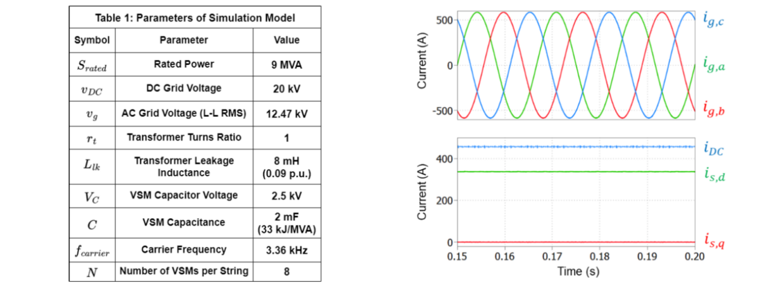
Figure 6 - Table of ZMC simulation parameters and steady state operation results during rated power operation. The AC and DC grid currents and dq-frame VSM string currents are shown
Steady-state waveform captures of the simulated system are shown in Figure 6 and 7 when the converter is transferring 9 MW of power from the DC to the AC grid. Figure 6 shows the abc-frame AC grid currents as well as the DC grid current and dq-frame string currents which are used for control. It can be seen that both the DC and AC grid currents have low harmonic content and the AC currents are balanced and synchronized.
In Figure 7(a), the modulated phase A VSM string voltage ??Σ,? as well as the grid voltage reflected through the Zig-Zag transformer ???,? are shown. Notice the multilevel voltage waveform of ??Σ,?. Additionally, in Figure 7(b) the capacitor voltages of the individual VSMs of the upper and lower phase A strings are shown. It can be seen that the VSM capacitor voltages stay balanced near their nominal 2.5 kV value with a voltage ripple consisting of both a first and second harmonic component as predicted in Eq. (15).
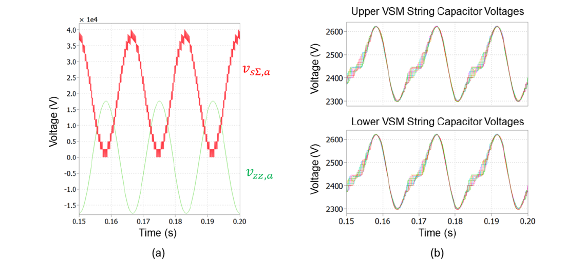
Figure 7 - Additional steady-state waveforms at rated power. (a) Phase A VSM string voltage and Zig-Zag transformer voltage waveforms. (b) Phase A upper and lower VSM string capacitor voltages
7. Experimental results
In addition to the simulated model, a simplified laboratory-scale prototype of the ZMC was constructed to verify the feasibility of the proposed topology and operation in a practical environment. The system parameters of the experimental setup are listed in Table 2 along with a circuit schematic in Figure 8. Due to lab equipment availability, only a single VSM is used in each string with all of the phases sharing a common capacitor in the upper and lower VSM. A bidirectional DC power supply set to 150 V is used to form the DC grid. Three individual three-winding transformers are wired in the Zig-Zag configuration and connected to a 110 V RMS line-to-neutral AC grid. While this simplified experimental system cannot validate all aspects of the proposed operation such as VSM balancing via sorting algorithms, it is able to demonstrate the practical viability of the integrated Zig-Zag transformer and DC flux cancellation.
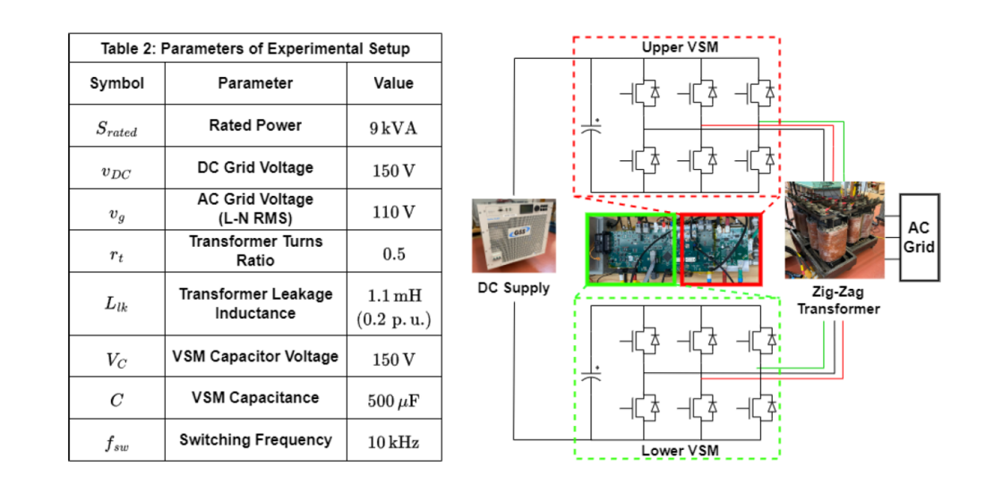
Figure 8 - Schematic of experimental setup with table of parameter values
Oscilloscope captures during experimental testing of the prototype are shown in Figure 9. These waveforms were obtained during steady-state operation when the converter is transferring 2.25 kW of power from the DC source to the AC grid. In Figure 9(a) the AC and DC grid currents are shown demonstrating effective regulation by the controller. The distortion-free AC grid currents also confirm that no transformer core saturation is occurring despite the high DC current flowing through the ZMC. Additionally, in Figure 9(b) the VSM string currents are shown as well as ??,?, the 3-level switching voltage generated across the phase A Zig-Zag transformer terminals U,A and L,A in Figure 2.
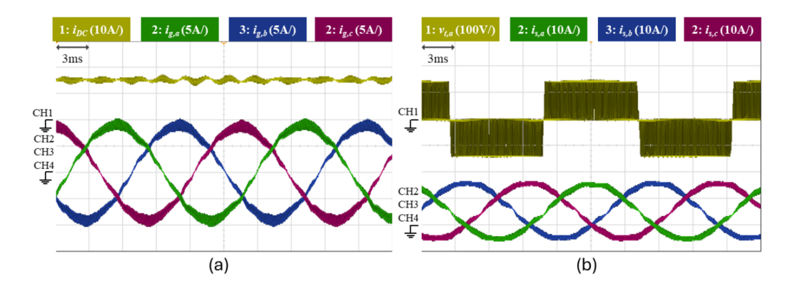
Figure 9 - (a) Oscilloscope capture showing AC grid currents and DC grid current when transferring 2.25 kW of power from the DC grid to the AC grid. (b) Oscilloscope capture showing string currents and 3-level AC voltage generated by VSM modulation
8. Conclusion
By directly integrating a Zig-Zag transformer in series with the VSM strings, the proposed ZMC offers a new alternative to traditional MMC topologies. The principal advantage of the ZMC is the elimination of expensive arm inductors through its utilization of the integrated transformer’s leakage inductance. Moreover, the Zig-Zag configuration offers flux cancellation of the DC string currents, minimizing the transformer core size and cost. In addition to presenting the new topology, this paper has provided an overview of the operating principles and control of the ZMC. It is shown that operation of the ZMC effectively decouples the DC and AC power systems as only the AC grid appears in the α and β equivalent circuits whereas only the DC grid appears in the common-mode (0) circuit. Furthermore, the ZMC offers simpler control as it possesses only three independent current paths. Finally, simulation and experimental results have been presented which validate the feasibility of the proposed topology and operation. A subject for future work is the analysis of converter behaviour under unbalanced or faulted grid conditions and the development of appropriate control schemes in these situations.
Acknowledgements
This work was supported by the Natural Sciences and Engineering Research Council of Canada under the Discovery Grants program under Grant RGPIN-2019-06453.
References
- A. Lesnicar and R. Marquardt “An innovative modular multilevel converter topology suitable for a wide power range” (IEEE Power Tech Conference, June 2003)
- K. Sharifabadi, L. Harnefors, H.-P. Nee, S. Norrga, and R. Teodorescu “Design, Control, and Application of Modular Multilevel Converters for HVDC Transmission Systems” (Wiley-IEEE Press, 2016, pages 7-177)
- A. Christe and D. Dujić “On the integration of low frequency transformer into modular multilevel converter” (IEEE Energy Conversion Congress and Exposition, September 2015, pages 3585–3592)
- A. Das, H. Nademi, and L. Norum “A new circuit topology of Modular Multilevel Converter (MMC) with an open end transformer” (International Exhibition and Conference for Power Electronics Intelligent Motion Renewable Energy and Energy Management, May 2012, pages 1128 - 1134)
- S. Tamada, Y. Nakazawa, and S. Irokawa “A proposal of modular multilevel converter applying three winding transformer” (International Power Electronics Conference, May 2014, pages 1357–1364)
- Y. Li and G. J. Kish "Comparative Assessment of Multi-Port MMCs for High-Power Applications" (IEEE Access, volume 10, February 2022, pages 22049 - 22060)
- H.-L. Jou, J.-C. Wu, K.-D. Wu, W.-J. Chiang, and Y.-H. Chen “Analysis of zigzag transformer applying in the three-phase four-wire distribution power system” (IEEE Transactions on Power Delivery, volume 20, number 2, April 2005, pages 1168–1173)
- Working Group B4 CIGRE. “The CIGRE B4 DC Grid Test System,” (ELECTRA number 270, October 2013, pages 10-19)
- C. J. O’Rourke, M. M. Qasim, M. R. Overlin and J. L. Kirtley "A Geometric Interpretation of Reference Frames and Transformations: dq0, Clarke, and Park" (IEEE Transactions on Energy Conversion, volume 34, number 4, December 2019, pages 2070-2083)
- B. A. Francis and W. M. Wonham “The internal model principle for linear multivariable regulators” (Applied Mathematics & Optimization, volume 2, number 2, June 1975, pages 170–194)
- R. Teodorescu, F. Blaabjerg, M. Liserre, and P. C. Loh “Proportional-resonant controllers and filters for grid-connected voltage-source converters” (IEE Proceedings - Electric Power Applications, volume 153, number 5, September 2006, pages 750-762)