Security Criterion for Distance Zone 1 Applications in High SIR Systems With CCVTs – Part 2: Steady-State Errors
Authors
B. KASZTENNY, R. CHOWDHURY - Schweitzer Engineering Laboratories, Inc., USA

Part 1 available on this page
Summary
In this two-part paper, we present a practical engineering procedure for verifying security of a directly tripping distance Zone 1 protection element in applications to lines with high source-to-line impedance ratios. In this part, we consider steady-state errors caused by instrument transformer errors, line impedance errors, ground potential rise, and mutual coupling. Part 1 considers transient security errors caused by capacitively coupled voltage transformers.
While factors that impact the Zone 1 security are generally known, there are no practical procedures for verifying the security of Zone 1 applications based on simple engineering calculations that use readily available data. This paper closes this gap by proposing how to quantify the impact of key interfering factors and showing how to verify the Zone 1 security.
The presented Zone 1 security criterion is intended to guide practitioners by either confirming the protection security of the preferred Zone 1 application or directing them to change application parameters, such as reducing the reach setting or adding a time delay.
Keywords
Distance protection, source impedance ratio, steady-state instrument transformer errors, Zone 11. Introduction
An underreaching directly tripping Zone 1 distance element is a valuable option for line protection. It operates without reliance on a protection channel. For lines without a protection channel, it provides primary protection. For lines with a protection channel – available to most lines today – it provides redundancy for communications-assisted protection schemes, such as directional comparison schemes and line current differential schemes. The directly tripping Zone 1 element may also reduce the protection operating time, especially if the protection channel is relatively slow while the line is relatively long and the local terminal is relatively strong.
For a Zone 1 element to trip without communications assistance, it must be secure. Directional supervision built into the Zone 1 elements ensures directional integrity for reverse faults. Therefore, from the application perspective, the Zone 1 security is only concerned with overreaching (tripping for forward out-of-zone faults). We classify the Zone 1 overreach as either a transient overreach (focus of Part 1 [1]) or a persistent overreach (focus of Part 2). These two types have different causes and solutions [2]. Both Part 1 and Part 2 are available together as [3]. Persistent overreach is caused by steady-state errors in voltages and currents, including voltage transformer (VT) ratio errors, current transformer (CT) ratio errors, errors in the line impedance value (magnitude and angle, positive- and zero-sequence), infeed and mutual coupling effects, as well as ground potential rise (GPR) [2].
Persistent errors may be addressed by shortening the Zone 1 reach. We define persistent errors as steady-state errors during fault conditions and use persistent and steady-state interchangeably.
High source-to-line impedance ratio (SIR) applications dramatically exacerbate the danger of Zone 1 overreach – both transient and persistent. When the SIR is high, the relay voltage for faults at the remote bus is low (so is the loop voltage of a distance element). The distance element operating signal (IZ – V) is even smaller [2]. When a protection operating signal is small, even small errors in voltages and currents may impact security.
The impact of a high SIR on the security of distance Zone 1 protection elements is well understood [2] [4]. However, because a combination of several factors affects the Zone 1 security, no accurate and practical criterion exists for verifying the security of the Zone 1 applications. The classification of transmission lines into short, medium, and long included in the IEEE Std C37.113-2015 (Line Protection Guide) [5] omits many of the practical dimensions of the impact of the SIR on Zone 1 applications, making it too simplistic to be a practical security criterion. Additionally, the Line Protection Guide [5] does not provide application recommendations that would depend on the SIR or the line length.
Consequently, a practitioner may be left with a void and uncertainty regarding the security of a Zone 1 application. Reference [2] provides an in-depth description and analysis of the relevant factors but does not include specific methods for engineering a particular application. This paper builds on [2] to provide simple and practical methods that quantify the relevant factors to verify the Zone 1 security in high SIR applications. Both the transient overreach and the persistent overreach criteria start with these input data:
- Worst-case SIR values for phase and ground faults obtained from a short-circuit program.
- Intended Zone 1 reach setting.
The Zone 1 security criterion we present in this paper for persistent overreach is based on the following data:
- VT and relay voltage accuracy specification.
- General information related to GPR.
- Short-circuit current in parallel lines, if these lines are magnetically coupled to the protected line, and the parallel line current that is large relative to the protected line current.
The persistent overreach security criterion allows the practitioners to balance the reach setting against the VT and relay errors and the impact of GPR and mutual coupling.
This part of the paper is organized as follows. Section 2 explains the Zone 1 operating signal and shows how to use it when analyzing the impact of errors on Zone 1 security. Section 3 derives the Zone 1 security criterion in relation to steady-state errors that are independent of the measured voltage and current. Section 4 summarizes the calculations for steady-state errors and provides a step-by-step procedure to follow. Section 5 explains how to combine the various errors when selecting the final Zone 1 reach setting, while Section 6 discusses how our findings compare with the IEEE Std C37.113 Line Protection Guide and field experience.
2. Zone 1 Operating Signal and SIR
2.1. Zone 1 Operating Signal
The distance element operating signal (IZ – V) is convenient when explaining and analyzing Zone 1 security issues [2]. In the IZ – V term, which is a voltage term, I is the loop current, V is the loop voltage, and Z is the impedance corresponding to the reach point of the Zone 1 element. The IZ – V operating signal applies universally to all distance element implementations. It also applies to both the mho and reactance operating characteristics. A Zone 1 element operates based on a phase comparison of the IZ – V operating signal and the selected polarizing signal.
Voltage errors do not impact the Zone 1 polarizing signal because the polarizing signal is derived by using memory (memory-polarized mho elements) or current (reactance elements). It is only the IZ – V operating signal that is impacted by both the transient and persistent errors in the loop voltage and current and the persistent errors in the reach impedance. This observation allows us to develop a common Zone 1 security criterion for both the mho and the quadrilateral distance elements.
A Zone 1 element in a distance relay measures the voltages and currents and effectively acts on the IZ – V operating signal. We can think of the measured IZ – V operating signal as comprising the true IZ – V operating signal and an error. The IZ – V operating signal is effectively a voltage, so we can write:
(1)
VERROR is the error in the loop voltage (V) or in the IZ term or both. The error in the IZ term results from the error in the loop current (I) or the reach impedance (Z).
Equation (1) provides a high-level concept. Different relays apply different low-pass or band-pass filtering before obtaining the IZ – V operating signal. When processing the IZ – V operating signal, some distance relays use phasors and phase comparators, while other relays use instantaneous values and coincidence timing. Some relays use the IZ – V term explicitly, while other relays perform equivalent calculations, such as the m-calculation, the polarized apparent impedance calculations, or the torque calculations [6]. Conceptually, however, we can analyze all these relays by looking at the true IZ – V operating signal in relation to the error signal, VERROR.
The main point of (1) is that as long as the magnitude of the error (VERROR) is small compared to that of the true IZ – V operating signal, the measured IZ – V operating signal has the correct polarity or phase angle relationship relative to the polarizing signal, and the Zone 1 element operates correctly. Therefore, we can conceptualize the Zone 1 security criterion as follows:
(2)
where | | stands for magnitude.
Condition (2) allows us to simplify the analysis by neglecting the relative polarities of the true IZ – V operating signal and the error signal. These two signals can effectively add or subtract. When the error signal has the same polarity as the true operating signal, it increases the measured operating signal and the Zone 1 element will not overreach. When the error signal has the opposite polarity as the true operating signal, it decreases the measured operating signal; if the measured operating signal polarity is inverted, the Zone 1 element overreaches. By requiring that the error signal be smaller than the true operating signal, we ensure that the measured operating signal polarity will not be inverted and the element will not overreach.
The true IZ – V operating signal in per-unit values of the loop nominal voltage depends on the SIR and the Zone 1 per-unit reach (m1), as shown in (3) [2]:
(3)
where m is the per-unit fault location.
2.2. Source-to-Line Impedance Ratio
Recently, a common agreement emerged that the SIR is based on the per-unit relay voltage magnitude for a metallic remote bus fault instead of the line and system impedances [2] [7] [8]. This improved SIR definition is consistent with thinking of the SIR as a parameter in a voltage divider that represents the simplified faulted-loop circuit. In this concept, the SIR determines how high or low the relay voltage is for a fault at the end of the protected line. This recent understanding of the SIR makes (3) exact.
As a result of linking the SIR to the relay voltage for a remote bus fault, two SIR values must be considered: SIRLL and SIRLG , for phase and ground faults, respectively. SIRLL is for evaluating the security of the Zone 1 phase element. SIRLG is for evaluating the security of the Zone 1 ground element. SIRLG is often lower than SIRLL because of the grounding paths presented by network transformers. For simplicity, we use a single variable SIR in this paper and avoid differentiating between the phase and ground elements, unless necessary. In addition to experiencing different SIR values, the Zone 1 phase and ground elements may use different reach settings. As a result, the security of the Zone 1 phase and ground elements must be verified separately. For simplicity, we use a single variable for Zone 1 reach (m1) and avoid differentiating between the phase and ground elements, unless necessary.
As expected, (3) shows us that the operating signal is zero when the fault is located at the reach point (m = m1). When the fault moves away from the reach point, either inside Zone 1 (m < m1, internal fault) or outside Zone 1 (m > m1, external fault), the operating signal increases proportionally to the difference between m and m1.
We are concerned with the Zone 1 security (an overreach for a remote bus fault), and therefore, we consider the IZ – V value not for any fault location (m) but for the closest external fault in the Zone 1 direction, i.e., for a remote bus fault (m = 1). Inserting m = 1 in (3) gives us:
(4)
Because Zone 1 is set to underreach (m1 < 1), we can remove the absolute sign in (4). Equation (4) allows us to account for the SIR: the weaker the system, the smaller the IZ – V operating signal and the greater the security problem. Equation (4) also allows us to account for the Zone 1 reach, m1: the longer the reach, the smaller the IZ – V operating signal and the greater the security problem.
We combine (4) and (2) and obtain a general Zone 1 security criterion as follows:
(5)
Condition (5) shows a Zone 1 margin of 1 – m1. To understand this margin better, we distinguish between two types of errors: ratio errors and fixed errors.
2.3. Ratio Errors and Fixed Errors
A ratio error, when considered within the specified measurement range, is a small error that is proportional to the quantity of interest (measured loop voltage, measured loop current, or the impedance used in the relay settings). Ratio errors are best accommodated by reducing the reach in proportion to the sum of the percentage errors, as explained in [2]. For example, assume that the voltage ratio error is 2 percent, the current ratio error is 5 percent, and the impedance error is 5 percent. To ensure Zone 1 security in the presence of these errors, the Zone 1 reach must be reduced from the theoretical limit of 1 pu by at least 2 + 5 + 5 = 12 percent (Zone 1 shall be set below 100 – 12 = 88 percent of the line impedance, in this example).
A fixed error is an error that is independent of the measured voltage and current. For example, a CCVT transient is proportional to the change between the pre-fault and fault voltages and is not proportional to just the measured fault voltage. On the contrary, the CCVT transient can be many times larger than the measured fault voltage. Or a voltage induced by mutual coupling and appearing as an error signal in the measured voltage for the protected line is proportional to the current in the parallel line and not to the measured current in the protected line. Fixed errors are best accommodated by using (5) to further reduce the Zone 1 reach after reducing it to account for the ratio errors.
3. Steady-State Security Criterion
Steady-state errors associated with the voltage and current measurements and the line impedance data impact the Zone 1 security and should be accommodated by shortening the Zone 1 reach or disabling the Zone 1 protection. The following steady-state errors may impact Zone 1 operation (see [2]):
- VT and CT errors.
- Relay voltage and current input errors.
- Line impedance errors.
- GPR.
- Mutual coupling.
Even in high SIR applications, the relay currents are well within the accurate measurement range of CTs and protective relays. Therefore, we can neglect the CT errors and the relay current input errors. These errors are small (at the level of 2 to 5 percent of the measured value). Moreover, they are ratio errors (i.e., they are proportional to the measured current) and, as such, are already included in the customary Zone 1 reach setting margin.
The lack of or imperfect line transposition adds to the line impedance errors. Only a perfectly transposed line is fully defined by the positive- and zero-sequence impedances, Z1 and Z0, respectively, and has all six loop apparent impedances equal to the positive-sequence impedance. During remote bus faults at the end of an untransposed line, a distance relay measures slightly different loop apparent impedances depending on the fault type and faulted phases. Differences in the apparent impedance magnitude of 5 percent are not uncommon. Also, inaccuracy in the zero-sequence compensation factor (k0 ) may affect the measured apparent impedance for ground faults. In this paper, we assume that the user has already accounted for the line impedance errors in the customary Zone 1 reach setting margin. For example, the phase distance Zone 1 reach is set based on the lowest apparent impedance of all three phase loops, and the ground distance Zone 1 reach is set based on the lowest apparent impedance of all three ground loops with additional margin for uncertainty in the k0 factor [2].
This section addresses the remaining sources of steady-state errors. It is important to realize that all the remaining errors are voltage errors that are not necessarily proportional to the measured voltage. For example, when the primary voltage is just a few percent of the nominal value, the VT and relay errors are not specified as a percentage of the measured value. Similarly, the GPR that affects the voltage that the VT measures is not proportional to the relay voltage or current but is related to the total ground current flowing into the substation ground. Similarly, the voltage induced through mutual coupling is proportional to the current in the coupled line and has no relationship with the voltage or current measured in the protected line.
Because the steady-state voltage errors tend to be a fixed portion of the nominal voltage and not the measured voltage, reducing the Zone 1 reach by the percentage error is not a proper way to accommodate these errors. Any error that is moderate and proportional to the voltage and current measurement is accommodated in the reach setting [2]. Instead, we will use (5) to evaluate the Zone 1 security in relation to the steady-state errors because (5) applies to the case of a fixed voltage error rather than a percentage voltage error. We use (5) and write that the Zone 1 per-unit operating signal must be greater than the worst-case steady-state error in the loop voltage, ESS:
(6)
where ESS is in per unit of the nominal loop voltage.
Of course, the shorter the per-unit reach (m1) and the lower the SIR, the higher the operating signal (the left-hand side in (6)) and the easier it becomes for the Zone 1 element to overcome the ESS error.
Security condition (6) can be written as a “maximum SIR” condition:
(7)
Security condition (6) can also be written as a “maximum per-unit Zone 1 reach” condition:
(8)
Condition (7) teaches us that the shorter the Zone 1 reach and the smaller the steady-state error, the higher the maximum SIR. Condition (8) teaches us that the lower the SIR and the smaller the steadystate error, the longer the maximum Zone 1 reach. The above is exactly what we intuitively expect.
We can represent (6) graphically as straight lines on the SIR vs. m1 plane as in Figure 1.
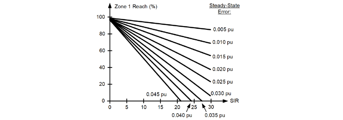
Figure 1 - Zone 1 security chart considering steady-state errors
For example, if the worst-case steady-state error is 0.025 pu and the SIR is 15, the margin for the fixed errors must be at least 40 percent of the line impedance (the reach must be below 60 percent).
Let us now turn our attention to estimating the worst-case steady-state voltage error. We assume that the individual error components accumulate (add) and never cancel (partially subtract) and write:
ESS = EVT + EREL + EGPR + EMC (9)
where (all errors are in per unit of the nominal loop voltage):
EVT is the VT error.
EREL is the relay voltage input error.
EGPR is the error associated with GPR (applies in most cases).
EMC is the voltage error associated with mutual coupling (applies in rare cases).
The following subsections propose how to estimate these errors for practical applications based on the minimum amount of readily available data.
3.1. VT and Relay Voltage Magnitude Errors
The accuracy specifications for the VTs and the relay voltage inputs follow a similar format. In the specified measuring range, these devices exhibit a ratio error, i.e., an error that is a fixed percentage of the measured voltage. The measuring range of a VT may start as low as 10 percent of the nominal value. The measuring range of a relay may start at as low as 1 V secondary. The claimed accuracies can be on the order of half a percent.
Figure 2 illustrates these magnitude errors by plotting the ratio error in blue (percentage of reading) and the absolute error in red (percentage of nominal).

Figure 2 - Measuring range, ratio error (blue), and absolute error (red)
As a worst-case scenario, we assume that, in applications with high SIR values, the relay voltage is outside the measuring range (below the lower limit of the range, VMIN(PU)). Therefore, we do not have explicit data about accuracy of the VT or the relay voltage inputs for a fault that causes a very low voltage at the relay location. We know, however, that the absolute error will not increase when the voltage decreases. Therefore, we assume that the absolute error (percentage of nominal) remains constant when the voltage is below the lowest voltage of the accuracy specification (see Figure 2).
Calculate the VT magnitude error in per unit of nominal as follows:
(10)
where E% is the percentage ratio error at the minimum voltage level specified, VMIN(PU).
Relay specifications often omit the VMIN(PU) value and use the convention of “x percentage of reading or ESEC V secondary, whichever is greater.” In such a case, calculate the relay voltage magnitude error in per unit of nominal as follows:
(11)
where VNOM is the nominal value of the voltage input (phase-to-ground voltage if using wye-connected VTs and phase-to-phase voltage if using delta-connected VTs) in secondary volts.
Before using (11), review the relay accuracy specification related to the accuracy of voltage-based protection. Do not consider voltage metering accuracy because relay metering functions typically apply more filtering and are therefore more accurate than the protection functions.
Consider the following examples.
Example 1
Assume a VT that has a class of 0.6 percent over the range between 90 percent and 110 percent of nominal [10]. We use VMIN(PU) = 0.9 pu and E% = 0.6 percent and calculate by using (10):
The above result means that for voltages below 90 percent of nominal, we expect the error to be below 0.54 percent of nominal. For example, if the voltage is 4.8 percent of nominal (SIR = 20), the error is 0.54 percent of nominal, or 11 percent of the measured voltage. If the SIR is 30, the voltage is 3.2 percent of nominal and the error is 17 percent of the measured value.
Example 2
Assume an IEC 61869-5 Class 6P VT [9], i.e., with a maximum error of 6 percent over the range between 5 percent and 100 percent of nominal. We use VMIN(PU) = 0.05 pu and E% = 6 percent and calculate by using (10):
The above result means that for voltages below 5 percent of nominal, we expect the error to be below 0.3 percent of nominal. For example, if the voltage is 4.8 percent of nominal (SIR = 20), the error is 0.3 percent of nominal, or 6.3 percent of the measured value. If the SIR is 30, the voltage is 3.2 percent of nominal and the error is 9.4 percent of the measured value.
Example 3
Assume that a relay with a 66.4 V secondary phase-to-ground nominal voltage has the following voltage protection accuracy claim.
Pickup Accuracy for Phase Voltage Elements:
±(0.25% of setting or 0.1 V sec, whichever is greater)
We use ESEC = 0.1 V and VNOM = 66.4 V and calculate by using (11):
As described in this subsection, the magnitude errors apply to voltages that are measured directly (ground distance elements and phase distance elements if the relay uses delta-connected VTs). In the next subsection, we analyze the phase voltage errors if the relay uses wye-connected VTs as is typically the case in transmission line protection.
3.2. VT and Relay Voltage Angle Errors
VTs and relay voltage inputs may exhibit small voltage angle errors on the order of a fraction of an electrical degree. These small errors are inconsequential even when the voltage is low, such as in high SIR applications, and can be neglected as long as the relay measures the operating voltage directly, i.e., ground distance elements and phase distance elements if the relay uses delta-connected VTs. However, we cannot neglect the angle errors when analyzing phase distance elements if the relay uses wye-connected VTs in applications where the phase SIRLL is high.
Figure 3 illustrates the worst-case scenario for deriving a phase-to-phase voltage from two measured phase-to-ground voltages. Because we are concerned with the Zone 1 overreach, we identify the case when the derived phase-to-phase voltage (red) appears smaller than the true phase-to-phase voltage (blue). The worst-case scenario requires the angle errors in the two measured phase-to-ground voltages to have opposite signs (shifting the two voltage phasors closer).
Further, the error in the derived phase-to-phase voltage increases when the magnitudes of the two measured phase-to-ground voltages are larger – for example, for phase-to-phase faults but not necessarily for phase-to-phase-to-ground or three-phase faults.

Figure 3 - Illustration of the measuring error in phase-to-phase voltage derived from two phase-to-ground voltages
Calculating the exact error in the derived phase-to-phase voltage in Figure 3 requires the magnitudes of the phase-to-ground voltages and the magnitude of the true phase-to-phase voltage. These magnitudes, however, are complex functions of SIRLG and SIRLL. We can simplify the analysis by making the following additional worst-case assumptions: 1) the phase-to-ground voltages did not decrease during the fault (the SIRLG is low, or the fault does not involve ground) and 2) the true phase-to- phase voltage is much lower than the nominal phase-to-ground voltages. Under these assumptions, the error in the phase-to-phase voltage derived from the phase-to-ground voltages is (in per unit of nominal):
(12)
where δ is the combined phase angle error of the VT and the relay.
Example 4
Assume the relay angle error is 1° and the VT angle error is 0.5°. We use (12) and calculate the error in the derived phase-to-phase voltage as follows:
EANG = sin(1° + 0.5°) = 0.0262 pu
3.3. Combined VT and Relay Voltage Errors
We are ready now to estimate the combined VT and relay voltage input errors in per unit of nominal. Use the following formulas.
Zone 1 Ground Element and Zone 1 Phase Element if the Relay Uses Delta-Connected VTs
Because the relay measures the operating voltage directly, the phase angle errors of the VT and the relay are inconsequential, while the VT and relay magnitude errors accumulate in the worst case. Therefore, use the following equation to calculate the combined errors of the VTs and the relay voltage inputs in per unit of nominal:
EVT + EREL = EVT_MAG + EREL_MAG (13)
Zone 1 Phase Element if the Relay Uses Wye-Connected VTs
In this case, the angle error or the magnitude error may play the dominating role. Use the following equation to calculate the combined error of the VT and the relay in per unit of nominal, considering that the magnitude and angle errors tend to be orthogonal; and therefore, we add them by using quadrature summation:
(14)
Typically, the combined VT and relay voltage error, when the loop voltage is very low, is about 0.02 pu of the nominal loop voltage.
3.4. GPR Error
The total ground current (3I0T) in the substation grounding resistance (RGPR) creates GPR voltage. The relay measures the protected line voltage relative to the substation ground, rather than the ideal (remote) earth. We can write the voltage drop equation for a ground fault with fault resistance (RF) and the total fault current (IF) as follows (see Figure 4):
(15)
where:
VR is the relay voltage (phase-to-substation-ground).
IR is the relay loop current for the Zone 1 ground element.
ZL is the impedance between the relay and the fault.
We use (15) to calculate the apparent impedance and obtain:
(16)
Equation (16) informs us that if the total ground current 3I0T and the relay loop current IR are approximately in phase, the apparent impedance shifts horizontally to the right, similarly to that of a resistive fault (see Figure 5). This added resistive component does not jeopardize the Zone 1 security, although it may reduce dependability, especially for short lines. However, if the network is not homogeneous, the angle of the 3I0T/IR ratio may tilt the added impedance down, potentially causing an overreach. A mho Zone 1 ground element polarized with memory voltage would expand its characteristic considerably in high SIR systems. This would extend its resistive reach and can result in unexpected operation for an external fault if the GPR impedance component in Figure 5 is tilted down. A quadrilateral Zone 1 ground element may be configured with a substantial resistive reach, and it may also overreach because of the tilted GPR impedance component.
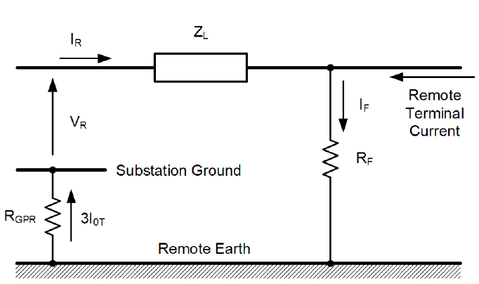
Figure 4 - Impact of the GPR on the ground loop distance measurement
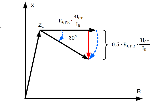
Figure 5 - Impact of the GPR on the distance element apparent impedance in homogeneous and nonhomogeneous networks
Typically, the GPR results in the underreaching of ground distance elements and in the degraded accuracy of single-ended impedance-based fault locators for ground faults. Because of the network nonhomogeneity, the GPR may also result in security issues for the Zone 1 ground elements.
We consider the following three cases for the Zone 1 ground distance elements:
No Grounding Path in the Substation (3I0T = 0)
For substations without grounding banks (switching stations), neglect the impact of GPR and assume EGPR = 0.
Inductive Grounding Path in the Substation
Assume the worst-case nonhomogeneity angle of 30 degrees (the angle between the 3I0T and IR). A 30-degree angle tilt results in a downward shift of the added GPR apparent impedance of half the GPR apparent impedance (see Figure 5). Therefore, use of EGPR = 0.5 ∙ VGPR(PU).
Inverted Grounding Path Current in the Substation Due to Autotransformers
If the substation grounding path is provided at least in part through certain autotransformers, the 3I0T current may be significantly shifted, or even inverted, compared to the IR current. In those cases, use EGPR = VGPR(PU) as a precaution.
You can also simplify the GPR analysis and assume EGPR = VGPR(PU) for all cases. Of course, the GPR error applies only to ground elements and not phase elements.
The value of the GPR voltage can be estimated based on the ratings of communications cables connecting substation equipment with facilities outside the substation. You can consider using 2 kV as a reasonable estimate of the GPR [11], but a more accurate estimate reflecting the utility’s substation grounding design practices should be used, if available.
Example
Assume a typical substation grounding through power or zig-zag transformers and estimate the EGPR error for two systems: 500 kV and 69 kV. We use the recommended 50 percent of the 2 kV value and calculate the following estimates.
500 kV system:
69 kV system:
As we see, the GPR impact is much smaller at higher voltages. In low SIR applications, the GPR voltage is an inconsequential fraction of the relay voltage for faults at the remote bus. In high SIR applications, the GPR voltage plays a significant role.
3.5. Mutual Coupling Error
A current that flows in a line that is magnetically coupled to the protected line induces a voltage in the protected line. In general, all sequence current components induce all sequence voltage components because the conductors are not spaced to perfectly cancel the relevant magnetic fields. For example, the positive-sequence current in the coupled line induces a negative-sequence voltage in the protected line. However, the zero-sequence coupling is by far the strongest (the zero-sequence current in the coupled line induces zero-sequence voltage in the protected line). Practitioners are well aware of the zero-sequence mutual coupling; the short-circuit programs model it, and the ground distance elements are set to account for it. The other modes of coupling are neglected, and the short-circuit programs do not model them.
In high SIR applications, even a small additional voltage resulting from the neglected mutual coupling can be significant when compared with the IZ – V operating signal of the Zone 1 element. This is especially the case if the coupled line carries much higher current than the protected line [2]. Additionally, while the higher current in the coupled line normally causes an underreach when considering only the zero-sequence mutual coupling, the typically neglected modes of coupling can cause overreach in high SIR applications.
One can use the line constants program to calculate the full coupling matrix for two 3-phase lines (a 6x6 matrix) and use it to calculate the impact of the coupled line currents on the loop voltages in the protected line during various fault types.
In this paper, we propose a much simpler method to approximate the impact of mutual coupling on the error in the loop voltage, EMC.
We performed the following studies to obtain our formula:
- We considered a bolted fault at the remote end of the protected line with another line running in close proximity but not connected to the same buses. The other line carries a current that is independent of the current in the protected line.
- We considered two configurations for each fault. In the first configuration, the two lines are mutually coupled. In the second configuration, the conductors of the two lines are spaced apart so that no appreciable coupling is between the lines.
- We considered the lines not transposed; each distance protection loop has a slightly different loop voltage depending on which phases are faulted (for example, AB vs. BC). We considered all 11 fault types. For phase-to-phase-to-ground faults, we considered the impact of coupling on the associated phase loop voltages and neglected the impact on the phase-to-ground voltages (distance relays measure phase apparent impedance during phase-to-phase-to-ground faults). For three-phase faults, we considered all three phase loop voltages.
- We logged the loop voltages for the cases with and without coupling and calculated the magnitude of the difference in the loop voltage.
- We logged the phase currents in the coupled line during the fault and calculated the maximum magnitude for all three phases.
- We calculated the coupling as the ratio between the effect (the change in the loop voltage) and the cause (the maximum phase current in the coupled line). We related this ratio to a unit of length of coupling (per mile or kilometer).
- For ground loops, we calculated the change in the sum of the positive- and negative-sequence components in the loop voltage. This approach removes the impact of the zero-sequence coupling.
- We repeated the test for other line configurations and logged the highest coupling for different tower and conductor configurations and different voltage levels.
We obtained the following worst-case coupling coefficient for 60 Hz systems:
0.100 V per A per mi
Our finding means that for each mile of coupling and each ampere of current in the coupled line, the coupled line can introduce an error as great as 0.1 V in the loop voltage. For example, assume that a 230 kV 10 mi line is mutually coupled to another line and the maximum fault current in that line is 5 kA. You can expect a voltage error due to coupling as great as 0.1 ∙ 5,000 ∙ 10 = 5 kV. The 5 kV error is 5/230 = 2.17 percent of the nominal voltage for the phase distance elements and 5 ∙ √3/230 = 3.77 percent of the nominal voltage for the ground distance elements. The 2.17 percent and 3.77 percent errors may be inconsequential when the SIR is low. However, when the SIR is high and the relay voltage and the IZ – V operating signal is at the level of just a few percent of the nominal voltage, the induced voltage can cause security and dependability problems.
Calculate the approximate voltage error in the loop voltage due to the negative- and positive-sequence mutual coupling by using the following equation:
(17)
where:
IMC is the coupled line maximum current (primary amperes); this is the highest current of all three phases for all fault types.
LMC is the length of coupling in miles or kilometers.
XMC is the coupling coefficient as follows:
| Length Units | Frequency HZ | |
| 60 | 50 | |
| Miles | 0.100 | 0.083 |
| Kilometers | 0.062 | 0.052 |
Compute (17) in primary units to avoid confusion regarding the system nominal voltage levels (the protected and the coupled lines can operate at different nominal voltages) and the VT and CT ratios (the two lines can be equipped with instrument transformers of different ratios). Before you can add the EMC error to the steady-state error (9), you need to express it in per unit of the nominal loop voltage of the Zone 1 element of the protected line:
(18)
where VNOM(V pri) is the nominal system voltage in primary volts for the phase loops or of the nominal system voltage in primary volts for the ground loops.
The approximation (17) is the worst-case scenario because it assumes no transposition along the coupled line sections. If the two lines are mutually coupled for a long distance, it is likely that the two lines are transposed within the common section, and the coupling effect will be lower.

4. Step-by-Step Procedure for Assessing Steady-State Zone 1 Security and Examples
4.1. Step-by-Step Procedure
Follow these steps to assess the Zone 1 security for steady-state fixed errors:
- By using a short-circuit program and considering all credible contingencies, obtain the highest SIR value for your application.
- Obtain accuracy specifications for the VT and relay voltage inputs and calculate EVT + EREL by using (13) for the Zone 1 ground element and (14) for the Zone 1 phase element.
- Learn if the substation has “grounding sources” and if they are transformers or autotransformers. Obtain the GPR value or assume 2 kV and calculate EGPR as in Subsection 3.4.
- If a magnetically coupled line is present, obtain the highest faulted phase current in the coupled line for the same system configuration that results in the highest SIR for the protected line and calculate EMC by using (17) and (18). If multiple lines couple to the protected line, perform the calculations separately for each line and sum the errors.
- Add the error components by using (9) and apply (6) considering your preferred Zone 1 reach setting.
- If (6) is not satisfied, either reduce the reach and disable the Zone 1 element (phase and/or ground) or select system components that reduce the errors in (9).
Of course, the margin in the Zone 1 reach setting must accommodate all three categories of errors (ratio, transient, and fixed). Ensure that the margin in the final reach setting is large enough to cover all sources of error (see Section 5).
4.2. Steady-State Security Zone 1 Phase Element Example
Calculate a secure Zone 1 phase element reach for a 230 kV line in a 60 Hz system with a worst-case SIR of 4 considering the following: 1) the combined VT and relay voltage error is 0.03 pu and 2) there is a mutually coupled line over 10 miles long that carries 4 kA fault current for a remote bus fault for the worst-case SIR of 4.
Using (17) with XMC = 0.1 V/(A∙mi), we obtain:
Using (8) with a total error of 0.03 pu + 0.0174 pu = 0.0474 pu, we calculate the maximum reach setting as follows:
If the line was not mutually coupled, the maximum Zone 1 phase element reach for this application would be:
4.3. Steady-State Security Zone 1 Ground Element Example
Calculate a secure Zone 1 ground element reach for a 230 kV line with a worst-case SIR of 4 considering the following: 1) the combined VT and relay voltage error is 0.015 pu, 2) an inductive grounding path is at the substation, and 3) no mutually coupled line is in this application.
We calculate the error due to GPR as follows:
Using (8) with a total error of 0.015 pu + 0.0075 pu = 0.0225 pu, we calculate the maximum reach setting as follows:
5. Combining All Sources of Error
We have presented methods to calculate the maximum secure Zone 1 reach considering the ratio errors [2], transient errors (see Part 1 [1]), and fixed steady-state errors (Section 4). We recommend that you add the security margins for all these errors to obtain the final security margin and the corresponding Zone 1 reach. Use the following formula to obtain the final Zone 1 per-unit reach:
(19)
where the margins for the ratio, transient, and fixed errors are:
marginRATIO = 1 − m1RATIO (20a)
marginCCVT = 1 − m1CCVT (20b)
marginFIXED = 1 − m1FIXED (20c)
Substituting (20) into (19), we obtain the following formula for calculating the final Zone 1 reach that accounts for all three errors:
m1 = m1RATIO + m1CCVT + m1FIXED - 2 pu (21)
For example, if the margin for the ratio errors is 10 percent (m1RATIO = 0.90 pu), the margin for the CCVT transients is 10 percent (m1CCVT = 0.90 pu), the margin for the fixed errors is 20 percent (m1FIXED = 0.80 pu), and the final Zone 1 reach is 0.60 pu. Of course, when the final reach is negative, you must disable Zone 1.
Figure 6 shows an example of the maximum reach setting vs. the SIR by using (22) that combines a 10 percent ratio error (m1RATIO = 90 percent) with a range of fixed steady-state error values.
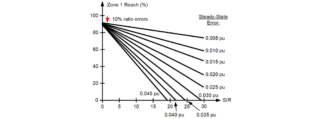
Figure 6 - Example Zone 1 security chart considering 10 percent ratio error and a range of fixed steady-state errors
6. IEEE C37.113 and Field Experience
Typically, a Zone 1 element is not set much greater than 80 percent of the line impedance. We know from experience that with the 80 percent setting, there are no Zone 1 security issues if the system is strong, and that one should expect security issues if the system is weak. The IEEE C37.113 Line Protection Guide uses an SIR of 0.5 as the upper limit for a strong system (definition of a “long line”) and an SIR of 4 as the lower limit of a weak system (definition of a “short line”). We apply our findings to explain the origins of the SIR of 0.5 and SIR of 4 in IEEE C37.113.
Assume that half of the 20 percent margin covers the ratio and fixed errors, and the other half covers CCVT transient errors.
Consider the CCVT transient errors and assume that the CCVT envelope is always below 40 percent, even for a very poorly performing CCVT [4]. We follow Part 1 of the paper and calculate the highest SIR for a secure Zone 1 application, assuming the margin of 10 percent (1 – m1 = 0.1 pu), and obtain SIR < 0.63. This SIR value is close to the arbitrary value of 0.5 in IEEE C37.113, and it confirms our field experience that in strong systems, a typically set Zone 1 element will not have any security issues due to the CCVT transients, even with CCVTs that have a very poor transient response.
Assume the system is not impacted by GPR or mutual coupling, and consider the combined ratio and fixed error of 0.025 pu. We use (7) and calculate the highest SIR for a secure Zone 1 application, assuming the margin of 10 percent (1 – m1 = 0.1 pu), and obtain SIR < 3. This SIR value is close to the arbitrary value of 4 in IEEE C37.113, and it confirms our field experience that in weak systems, a typically set Zone 1 element may have security issues, especially when the CCVT transients erode the initial 20 percent security margin.
7. Conclusions
In this part, we have presented an engineering method for quantifying the Zone 1 security in high SIR applications, including VT and relay measuring errors, GPR, and mutual coupling. Part 1 [1] discusses the impact of CCVT transients on the Zone 1 security. We have shown how to use the error estimates to verify the Zone 1 security and how to change the application parameters to ensure security.
The ratio measurement errors are proportional to the measured voltage and current. They are best accommodated by following a standard practice and shortening the Zone 1 reach to provide a percentage margin that is greater than the sum of the percentage ratio errors in the measured voltage, measured current, and line impedance. In applications to strong systems, you need to account for only the ratio errors and the zero-sequence mutual coupling. In applications to weak systems, you should consider the other two less-known classes of errors.
We have introduced a method to estimate the worst-case steady-state voltage errors that are independent of the measured voltage and current, and we have shown how to use these errors to verify the Zone 1 security. These errors include voltage measurement errors for high SIR conditions when 1) the relay voltages are very low and therefore outside the specified measurement range, and the measurement error is no longer a ratio error, 2) a GPR component is in the phase-to-ground voltages, or 3) the voltages are induced by lines that are mutually coupled with the protected line. We explain which data to collect and how to use them to verify the Zone 1 security.
If we expect to set the Zone 1 reach to 80 percent of the line impedance and assume the total steadystate voltage error is below 2.5 percent of nominal (VT and relay errors, no GPR or mutual coupling to a line that carries significant current), we can apply the Zone 1 element when the SIR is less than 3, assuming the transient errors require a margin that is less than 10 percent (see Section 6).
We can state that it is very unlikely that in systems with SIR values below about 3, and without significant GPR or mutual coupling, a typically set Zone 1 element (an 80 percent reach setting) would overreach because of steady-state errors, regardless of the VT and relay makes and models.
References
- B. Kasztenny and R. Chowdhury, “Security Criterion for Distance Zone 1 Applications in High SIR Systems With CCVTs – Part 1: Transient Errors,” proceedings of the 2024 CIGRE Canada Conference & Exhibition, Winnipeg, MB, Canada, 2024.
- B. Kasztenny, “Settings Considerations for Distance Elements in Line Protection Applications,” proceedings of the 74th Annual Conference for Protective Relay Engineers, College Station, TX, USA, 2021.
- B. Kasztenny and R. Chowdhury, “Security Criterion for Distance Zone 1 Applications in High SIR Systems With CCVTs,” proceedings of the 76th Annual Georgia Tech Protective Relaying Conference, Atlanta, GA, USA, 2023.
- B. Kasztenny, D. Sharples, V. Asaro, and M. Pozzuoli, “Distance Relays and Capacitive Voltage Transformers – Balancing Speed and Transient Overreach,” proceedings of the 54th Annual Georgia Tech Protective Relaying Conference, Atlanta, GA, USA, 2000.
- IEEE Std C37.113-2015, IEEE Guide for Protective Relay Applications to Transmission Lines.
- H. J. Altuve Ferrer and E. O. Schweitzer, III (eds.), Modern Solutions for Protection, Control, and Monitoring of Electric Power Systems, Schweitzer Engineering Laboratories, Inc., Pullman, WA, USA, 2010.
- P. G. Mysore and J. U. Berzins, “Impact of Voltage Transients and System Impedance Ratio on Zone 1 Distance Relay Reach,” proceedings of the 56th Annual Minnesota Power Systems Conference, Saint Paul, MN, USA, 2020.
- M. Thompson, D. Heidfeld, and D. Oakes, “Transmission Line Setting Calculations – Beyond the Cookbook Part II,” proceedings of the 48th Annual Western Protective Relay Conference, Spokane, WA, USA, 2021.
- IEC 61869-5:2011, Instrument Transformers – Part 5: Additional Requirements for Capacitor Voltage Transformers.
- IEEE Std C57.13-2016, IEEE Standard Requirements for Instrument Transformers.
- ANSI/IEEE Std 487-1980, Guide for the Protection of Wire-Line Communication Facilities Serving Electric Power Stations.
Biographies
Dr. Bogdan Kasztenny has 35 years of experience in power system protection and control. Bogdan has designed, applied, and supported protection, control, and fault-locating products with their global installations numbering in the thousands. Bogdan is an IEEE Fellow, an IET Fellow, a Senior Fulbright Fellow, and a Distinguished CIGRE Member. He has authored over 250 technical papers and holds over 60 U.S. patents.
Ritwik Chowdhury (M.Sc.) is a principal engineer at Schweitzer Engineering Laboratories, Inc. Ritwik holds over 15 patents and has coauthored over 30 technical papers. He is the chair of the Protection and Control Practices Subcommittee (I-SC) of the IEEE Power System Relaying and Control (PSRC) Committee and the recipient of the 2021 PSRC Outstanding Young Engineer Award. Ritwik is a senior member of IEEE, a member of CIGRE, and a registered professional engineer in the province of Ontario.