Distance protection in the vicinity of VSC: present Belgian situation and outlook
Authors
J. VERMUNICHT, R. LOENDERS, S. NAGELS, W. LETERME - Dept. Electrical Engineering, KU Leuven/EnergyVille, Leuven/Genk, Belgium
K. DE KERF, C. MOORS - Dept. Asset Management Sec. Systems, Elia Transmission Belgium
N. CHARELS - Dept. Elia Engineering Power Electronics, Elia Transmission Belgium

Summary
Converter-interfaced generation and HVDC interconnections are increasingly used in the power system. Voltage Source Converter (VSC) controls influence nearby distance protections on the AC side. Existing research studies different network topologies with a wide range of parameters, which makes it hard to determine from what point VSC interactions become problematic. This paper derives parameters that characterise the VSC’s impact on the apparent impedance and enable comparison of different grids. Second, the impact of Fault Ride-Through (FRT) control on the impedance locus is studied using EMT simulations and hardware tests. This study adopts a network near an actual VSC installation in Belgium under both present conditions and varying weak infeed conditions. In the studies, only with relatively large converter to synchronous short-circuit contributions, FRT controls have a significant negative impact on the impedance locus. However, initial tests under present infeed conditions did not show problematic VSC interactions.
Keywords
Apparent impedance, Distance protection, Fault Ride-Through, Line protection, VSC1. Introduction
Inverter-based generation and HVDC links, interfaced to the power system via voltage-source converter technology, are increasingly used within the power grid. These power-electronic devices have a considerably different response to short-circuit faults compared to conventional synchronous generation. VSCs provide fault currents with limited magnitude and with phase angles which are determined by the internal dynamics of the converter’s control loops [1]. The changes in the characteristics of fault currents impose challenges for protections in the vicinity of these VSCs, especially distance protections. Furthermore, and in contrast with synchronous generators, different Fault Ride-Through (FRT) control strategies can be applied for VSCs depending on the grid code, which diversifies those challenges [2], [3].
The literature reports different problems such as incorrect zone selection [1], [4]-[8] or incorrect identification of phase or fault direction [5], [9]. Attempting to mitigate these problems, recent studies propose new measures such as remedial actions on the algorithms used in the protection relay [10]-[12]. The authors of [13] compare the impact of a grid-forming (GFM) FRT strategy to a grid-following (GFL) strategy. Furthermore, time-domain protection might be considered as a potential solution for single ended line distance protection without communication requirements [10], [14]. Nevertheless, in most of these studies, major issues only arise whenever the VSC is the sole element that injects fault current at a certain bus.
As for now, it remains yet unclear how to define from what point VSC interactions become an issue for currently installed distance protection, and how to select the appropriate type of study to assess distance protection in the vicinity of a VSC.
First, comparison of effects seen in the literature is difficult given that a wide variety of network topologies is studied, with a wide range of network parameters. For example for line protection near a converter bus, the infeed on that bus can come solely from the converter, or partly from converter-interfaced and synchronous sources. Therefore, parameters are required to assess from what point in the grid distance protection becomes problematic given that a converter is added to the grid. Second, different options exist to study protection problems making use of either steady-state or transient models of the grid and VSC. Steady-state methods, e.g., the systematic analysis as presented in [15], require limited computational effort to study the apparent impedance. While more detailed transient models allow a time-domain analysis of the impedance locus including converter dynamics, but at the cost of increased complexity.
This paper (i) lists potential protection malfunctions found in the literature, (ii) proposes parameters to characterise the impact of VSC fault current injections on the apparent impedance, and (iii) studies the impedance locus of distance protection near a VSC HVDC converter using EMT-type models and hardware experiments. The studied network is based on an N-1 situation near a HVDC VSC in Belgium, although assuming weak infeed conditions. Finally, a sensitivity study is performed on the identified parameters to assess their impact on the impedance locus trajectory and correct functioning of the distance protection relay.
2. Protection malfunctions
The results of a literature review on line protection in the vicinity of VSC HVDC converters are presented in Table 1. It is concluded that there is a risk of protection failure. Conditions that contribute to these potential malfunctions are resistive and unbalanced faults under weakinfeed scenarios. The most probable failures in distance protection are: extended zone settling time, incorrect zone decision and incorrect fault phase selection or direction determination. For distance protections, malfunctions have been identified for both conventional algorithms (making use of impedances) as well as for incremental quantity algorithms applied to directional and phase selection elements (speeding up the decision-making process). It should be noted that a large share of problems can be attributed to the lack of negative sequence currents (e.g., elements making use of negative sequence currents to determine direction or phases, whereas the VSC internal control suppresses these). Another source of errors, especially in distance zone protection, lies in the controlled angle of the VSC fault current infeed at a local terminal in conjunction with a relatively large fault current fed in from the remote terminal. Given that replacement of synchronous machines by VSCs (especially without additional control) lowers the inertia in the power system, power swing detection issues may also start to arise. Last, weak infeed logic may not work in case the VSC maintains a sufficiently high voltage, e.g., for a highly resistive fault.
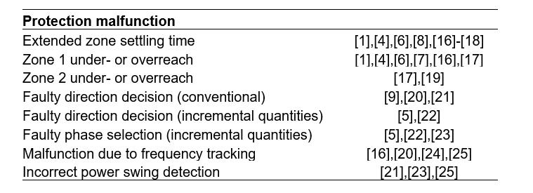
Table 1 - Identified potential protection malfunctions
3. background and preliminary analysis
Out of the potential malfunctions, the paper further considers the ones associated with distance protections, and especially the zone selection algorithm.
3.1. Studied network
The network in this study is based on an N-1 condition in the vicinity of a HVDC converter station in Belgium (Fig. 1). One transmission line is taken out compared to the present grid topology, this reduces the degrees of freedom. The aim of studying the reduced network 1 is twofold. First, it allows variation of the VSC fault current infeed relative to the synchronous infeed at a local and remote terminals. Second, it avoids studying an overly complex system. This model includes two equivalent Thévenin voltage sources with internal impedance Zsg1 and Zsg2 on either end of the transmission line and with a grey-box model of the VSC on the first bus. The model is built in PSCAD, which runs EMT simulations in non-real-time [26].
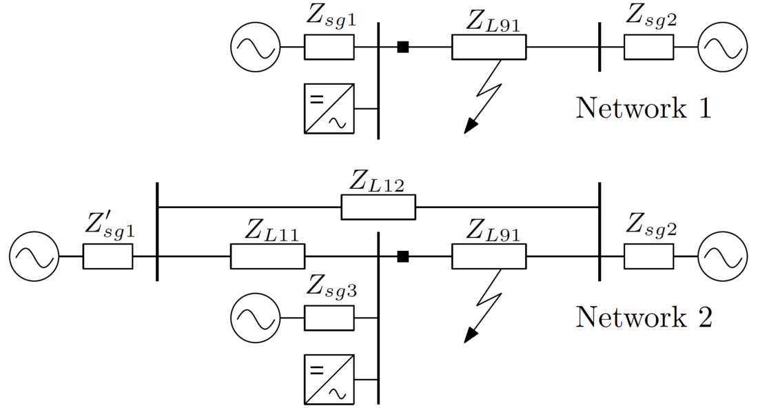
Figure 1 - Network 1 is the studied network topology. Network 2 is used as base case for initial tests. Network 1 is equivalent to network 2 for the case without line L12 (N-1). The impedance of line L11 and synchronous sources (Zsg3) at the local terminal in network 2 can be represented by one equivalent impedance in network 1. The relay under test is indicated by a black square
3.2. Apparent impedance
The apparent impedance is calculated from the currents and voltages measured at bus 1 by the relay (Fig. 2). Current I1 consists of a contribution from the converter and a synchronous grid equivalent. The fault is applied at x percent of the total line length, starting from bus 1.
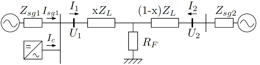
Figure 2 - Circuit diagram for the calculation of the apparent impedance
(1)
The apparent impedance can be decomposed into 3 components (1). These components are proportional to: (i) the fault distance x and line impedance ZL; (ii) the fault resistance RF and (iii) the remote current infeed I2 and fault resistance, and inversely proportional to the local current infeed I1. As is well known, the second and third components of (1) can cause under- or overreaching of the distance element.
3.3. Parameters to characterise VSC impact on the apparent impedance
A converter connected to this system mainly affects the third component of the apparent impedance (1). This component is detailed in (2). The effect of adding a converter is twofold. First, the converter impacts phase angle φ1. During the first cycles after fault incident, the phase angle of the converter current Ic can not be assumed constant as opposed to synchronous generators [1]. The angle of the converter current is variable and depends on VSC controls and FRT strategy. The effect of this changed phase angle φ1 is magnified by RF and the ratio |I2|/|I1|. Second, the current injection when adding a converter decreases the magnitude of the ratio |I2|/|I1| as I1 = Ic + Isg1.
(2)
Previous derivation allows to identify different influencing parameters that act on the phase angle and the magnitude of (2).
Acting on the phase angle:
- |Ic|/|I1|: this ratio determines the relative impact of the converter in controlling the phase angle φ1 of the current measured on the local bus. This ratio thus determines the vector angle of the third component in (1).
Acting on the magnitude:
- |I2|/|I1|: this ratio is proportional to the magnitude of the third component in (1). It depends on the relative strengths of the synchronous systems feeding in fault currents, with the fault current of the converter complementing the first system.
- RF : this factor equals the second component in (1). First, this component results in an impedance shift along R in the RX-diagram. Second, RF amplifies the magnitude of the third component in (1).
The VSC impact on the impedance locus is primarily determined by the relative infeed of the converter compared to the synchronous generation on the same bus. The converter impacts the current injection angle φ1, which in case of reactive injection mainly results in a shift of the apparent impedance along the imaginary axis, potentially affecting the estimation of the distance in a distance protection. The final impact of this angle shift on the apparent impedance is determined by the parameters that determine the magnitude of the primary effect (angle change).
3.4. Comparison of the parameters used in literature
A comparison of the parameters used in the literature reveals that protection malfunctions in general arise when (i) |Ic|/|I1| is close to 1, (ii) |I2|/|I1| takes a high value and (iii) RF is non-zero and sometimes taken as a high value (10 Ω) (Table 2). By comparing these parameters to the ones corresponding to the present grid conditions in the studied base case, those malfunctions are anticipated to be low.
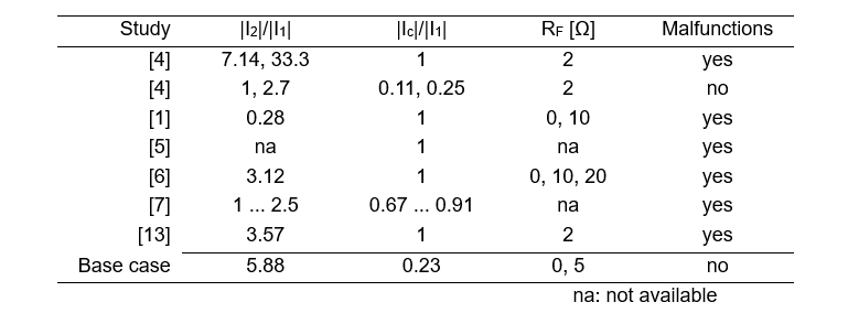
Table 2 - Overview of parameters that characterise the VSC impact on the apparent impedance. This table compares different studies from literature. Malfunctions are in general created through (i) keeping |Ic|/|I1| close to 1, (ii) assuming |I2|/|I1| high and (iii) combining that with a high RF.
The studies in Table 2 adopt different VSC FRT controls for example with different injection strategies for negative sequence currents. Comparison should thus be done with caution for the control strategies and control parameters of the individual studies.
4. Methodology
This work studies the impedance locus of distance protection near a VSC HVDC converter using EMT-type models and hardware experiments. The EMT-type models include an adequate representation of the system and converter dynamics. Voltage and current waveforms are computed with simulations and replayed on a distance protection relay in the lab.
First, the apparent impedance Zapp is calculated as function of time (impedance locus). This allows to assess if the impedance locus trespasses unwanted zones during the FRT transient. Next, the results are validated by hardware tests. The simulated waveforms are replayed on the protection relay using a signal generator. This is repeated for 288 fault scenarios under present system conditions and 6 scenarios under future conditions to study the variation of the parameters identified in section 3.3.
4.1. VSC fast fault current injection
The black-box converter model, implemented in EMT-type software, was benchmarked to an actual installation by the manufacturer with functional and dynamic performance tests using an HVDC and AC system model in a real-time simulation environment [27]. The model includes sub-module, current, FRT and outer controls. In general, the FRT controls are designed to approximate the fault behaviour of a synchronous generator. This is done by injecting a reactive current that supports positive sequence voltage and suppresses negative sequence voltage at the point of coupling. The FRT strategy of the VSC with GFL control is to inject reactive fault current at the point of common coupling. Positive and negative sequence current are injected as function of the voltage drop.
4.2. Studied base case with an extended network (network 2)
Initial tests were performed on network conditions closely resembling the present grid topology (network 2 from Fig. 1) and parameters near an actual VSC installation. No problems were found that could be related to VSC interactions, but rather to known effects of asymmetric infeed at both ends of the line. These findings are in agreement with literature as the ratio |Ic|/|I1| is small under present system conditions (Table 2).
The studied base case assumes short-circuit levels of the present system. 96 fault scenarios were tested in the lab under normal conditions with all transmission lines connected (Table 3). 192 scenarios were tested for conditions when line L11 is out (N-1).
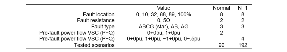
Table 3 - Fault and network parameters for the studied base case (network 2 Fig. 1). Number of tested scenarios under normal and N-1 conditions
4.3. Case studies on a reduced network (network 1)
To study VSC interactions, the adapted N-1 topology without line L12 (network 1 from Fig. 1) is adopted, and the parameters were varied to check the converter impact on the impedance locus. The parameters are varied by changing the short-circuit levels.
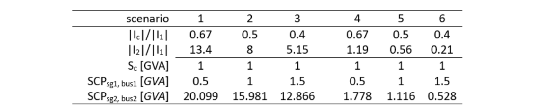
Table 4 - Short-circuit power (SCP) of the synchronous grid models and VSC parameters for 6 scenarios. The converter at bus 1 is rated at Sc = 1000MVA
This study considers 6 scenarios under varying infeed conditions (Table 4). These scenarios vary the parameters described in 3.3 by variation of the short-circuit power (SCP) of the grid equivalents at the local and remote bus. The total synchronous short-circuit power at the local (converter) bus SCPtot,bus1 is fixed at the value of either 7 GVA in scenarios 1-3 or 2 GVA in scenarios 4-6. This total synchronous SCP is allocated to sources sg1 and sg2 at the local and remote bus respectively. First, the local synchronous SCPsg1,bus1 is varied between 3 different values: 0.5, 1 and 1.5 multiplied by the rated power of the converter. This determines the ratio |Ic|/|I1|. Next, the remaining SCP is allocated to the remote source (3). Finally, this remaining SCPsg2,bus1 is referred to bus 2 by compensating for the line impedance in between both busses (4). The network parameters (Table 5) and fault parameters (Table 6) that have been taken constant throughout this study were selected in accordance with the Belgian TSO to resemble realistic network conditions.
(3)
(4)
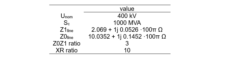
Table 5 - Network parameters

Table 6 - Fault parameters - constant
4.4. Lab Setup
For this study the considered Devices Under Test (DUT) are distance protection relays, which measure the fault impedance. These protection relays are commonly used for transmission line protection. To test the impact of fault current contribution of a VSC on the detection algorithms of the DUT a simplified power system model is proposed (section 3.1).
The simulation model is able to generate COMTRADE files (Common Format for Transient Data Exchange) sampled at 20 kHz, which allows replaying system events on the DUT using a signal generator (Omicron CMC256plus). Each simulation that is replayed on the DUT generates a new COMTRADE file, stored locally on the DUT, which contains aside from the measured currents and voltages, status signals from the different protection functions. This includes detection and operation information of the fault direction, the faulty phase-loops, and the predefined impedance zones. All this information is used to assess whether the DUT operated correctly. An overview of the automation process for this setup is shown in Fig. 3.
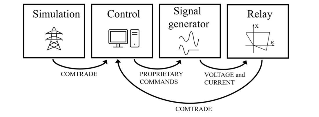
Figure 3 - Overview automated lab-setup
5. Results
5.1. Impedance locus affected by VSC FRT controls
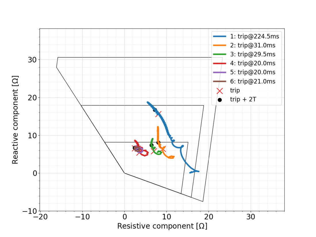
Time-domain simulations were performed to compute the trajectory of the impedance locus, and the simulated waveforms were applied on the protection relay. The impedance loci (Fig. 4a) cross different protection zones because of converter dynamics. A locus can start in one zone and converge towards a different zone, or oscillate between zones depending on momentary control state.
(a) With converter at bus 1
Figure 4 - Locus plot derived from the DUT for 6 infeed scenarios when a fault is applied. The trip time and 2 cycles (2T) after trip are indicated resp. with a red cross and black dot. The loci are plotted from 1 ms after fault incident onwards to enhance readability
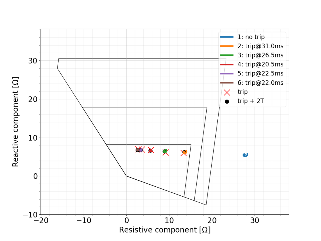
(b) Without converter at bus 1
Figure 4 - Locus plot derived from the DUT for 6 infeed scenarios when a fault is applied. The trip time and 2 cycles (2T) after trip are indicated resp. with a red cross and black dot. The loci are plotted from 1 ms after fault incident onwards to enhance readability
Similar results are found in [13] where zone discrimination issues are attributed to the oscillations on the measured impedance. Here the cause is related to the reaction of the converter current controls, which cannot follow the grid properly during low levels of voltage because of synchronisation issues from the Phase Locked Loop (PLL). This causes oscillations on the positive sequence currents, which cause the angle variation in the current.
Next the steady-state impedance is calculated for a situation with and without VSC added to the network (Table 7). This comparison is done for the 6 infeed scenarios from Table 4. With VSC connected, the impedance exceeds zone 1 (X = 8.15Ω) in 4 out of 6 scenarios, as is expected based on the parameters from the preliminary study in Table 4. By contrast, without VSC connected, the steady-state reactance remains within the boundaries of zone 1.

Table 7 - Steady-state impedance with resistance and reactance in Ω (for fault loop AG). The impedance is computed for six scenarios (sc) without and 6 with VSC current injection during a 3-phase fault
5.2. VSC versus synchronous infeed at the local, converter bus
In case of reactive current injection during a fault, the impact on injection angle φ1 results in a shift of the apparent impedance along the imaginary axis. The resulting current phase angle φ1 is influenced more by the converter when the overall converter contribution in the total local fault current I1 = Isg1+Ic increases (2).
Ratio |Ic|/|I1| decreases from scenario 1 to 3 as conventional local infeed (Isg1) increases. As a result the impedance locus shifts to the left and downwards. This is visible by comparing scenarios 1, 2 and 3 in Fig. 4. This may be explained on the one hand by a decreased effect of Ic on angle φ1, and on the other hand a decreased effect of |I2|/|I1| (infeed related).
There is a similarity between scenarios 1 and 4 in the evolution of the impedance locus. It should be noted that these scenarios have the same ratio |Ic|/|I1|. Coincidentally with the previous point, the rotation of the locus shifts clockwise when comparing scenarios 1, 2 and 3. This effect is also noticeable between scenarios 4, 5 and 6, but in the latter case on a smaller scale.
5.3. Variation of remote versus local infeed
As the infeed ratio |I2|/|I1| decreases from scenario 1 to 6, the overall size of the impedance locus shrinks and shifts to the left towards the true portion of the line impedance including the fault resistance (3.73+ j6.88 Ω). The starting point of the impedance trajectory shifts upward, and towards the settled impedance. This is most visible by comparing scenarios 1, 2 and 3 in Fig. 4. Ratio |I2|/|I1| thus determines the magnitude of the principal VSC impact (angle change). Additionally, the fault resistance has the same effect as this ratio on the apparent impedance.
5.4. Impedance as function of time
Without VSC connected to the network, the impedance converges faster to a steady-state value (Fig 5). By contrast with VSC, the reactance first goes approximately to zero around 0.415 s and ramps up next. The resistance then decreases accordingly. Rapid changes during the first cycles after fault incident relate to VSC controls that switch to reactive fault current injection. This reactive current injection initiates after about 5-20 ms after fault inception depending on fault type, and subsequently increases during circa 25 ms before settling. This corresponds with the control time-stages identified in [5]. Thereafter (from around 0.44 s onward) the impedance shows slower changes that can be related to outer loop controls. These slow changes cause oscillations of the impedance locus, leading to a potential longer settling time of the impedance.
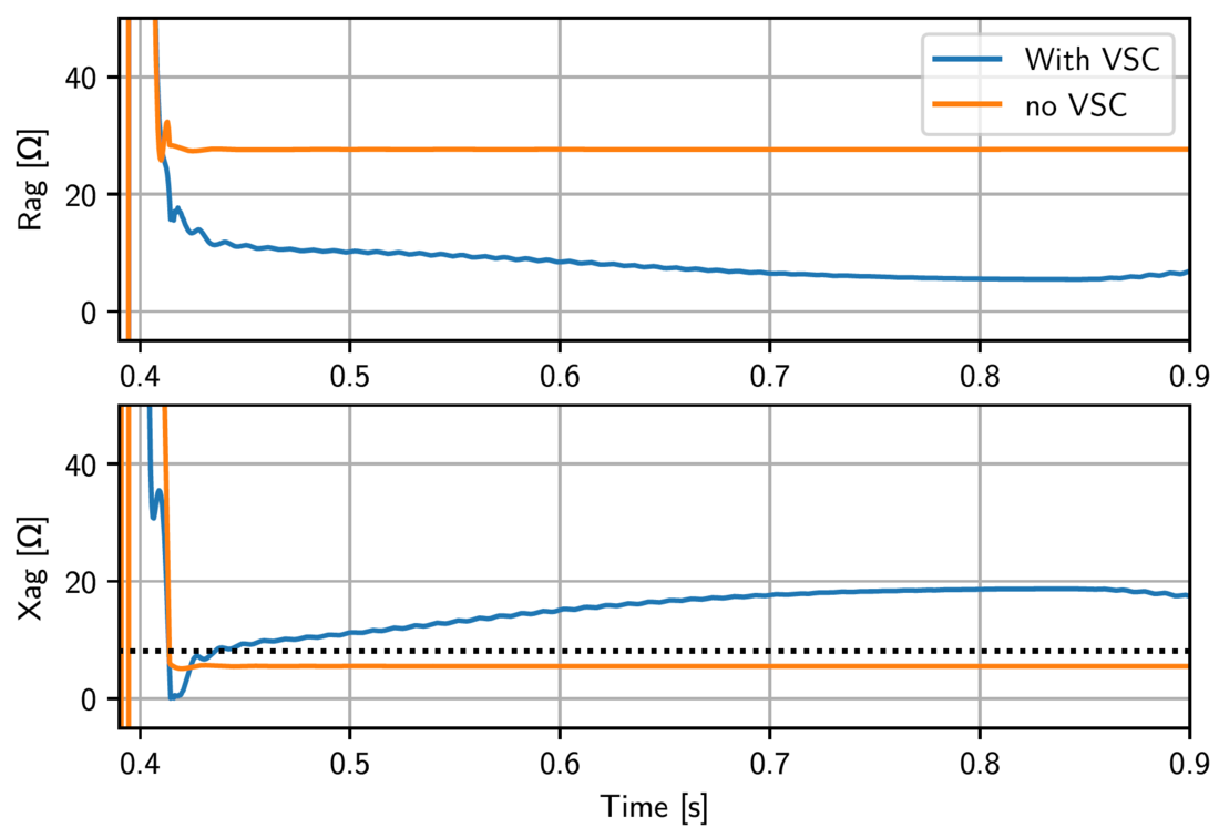
Figure 5 - Impedance derived from the DUT as function of time, for scenario 1 with and without VSC connected. The dotted black line indicates the reactance boundary of zone 1
6. Conclusions
For a real-life case in Belgium near a VSC HVDC converter, no distance protection malfunctions are anticipated due to VSC interactions. Present system conditions have a relatively small VSC fault current contribution compared to synchronous infeed at the converter bus. In contrast, for future grids, problems are expected mostly for a weak local terminal with relatively large VSC fault current, combined with a large fault current from a strong remote terminal. In that case VSC FRT controls have a significant impact on the impedance locus monitored by distance protection. Under altered grid conditions, results show incorrect zone decision and extended zone settling time. No issues are observed with direction decision or phase selection in the studied cases.
Parameters are derived that characterise the impact of VSCs on distance protections and enable a comparison of different grids. These parameters provide insight into how the VSC’s FRT control affects the apparent impedance. First, the relative VSC infeed compared to the synchronous infeed on that same bus impacts the angle of the apparent impedance. Second, the ratio of the fault current infeed from both transmission line ends determines the magnitude of this angle change together with the fault resistance. This ratio thus affects the magnitude of the principal VSC impact (angle change).
References
- A. Hooshyar, M. A. Azzouz, and E. F. El-Saadany, “Distance Protection of Lines Emanating From Full-Scale Converter-Interfaced Renewable Energy Power Plants—Part I: Problem Statement,” IEEE Transactions on Power Delivery, vol. 30, pp. 1770–1780, Aug. 2015.
- G. Ebner, B. Karacay, R. T. Pinto, E. Starschich, et al., “Enhanced voltage support with vsc-hvdc during unbalanced ac faults,” in CIGRÉ SC A3, B4 & D1 Colloquium, (Winnipeg, Canada), pp. 1–9, 2017.
- S. Rüberg, et al., “Demonstration of mitigation measures and clarification of unclear grid code requirements,” in EU h2020 Migrate project, no. Deliverable D1.6, 2019.
- C. Brantl, P. Ruffing, and R. Puffer, “The application of line protection relays in high voltage ac transmission grids considering the capabilities and limitations of connected mmcs,” in 15th International Conference on Developments in Power System Protection (DPSP 2020), (Liverpool, UK), pp. 1–6, 2020.
- D. López et. al., “Negative sequence current injection by power electronics based generators and its impact on faulted phase selection algorithms of distance protection,” inWestern Protective Relaying Conference (WPRC), (Spokane, Washington, USA), Sept. 2018.
- M. M. Alam, H. Leite, J. Liang, and A. da Silva Carvalho, “Effects of vsc based hvdc system on distance protection of transmission lines,” International Journal of Electrical Power Energy Systems, vol. 92, pp. 245–260, 2017.
- J. Jia, G. Yang, A. H. Nielsen, and P. Roenne-Hansen, “Hardware-in-the-loop tests on distance protection considering vsc fault-ride-through control strategies,” The Journal of Engineering, vol. 2018, no. 15, pp. 824–829, 2018.
- J. J. Chavez, M. Popov, A. Novikov, S. Azizi, and V. Terzija, “Protection function assessment of present relays for wind generator applications,” in International Conf. on Power Systems Transients (IPST2019), (Perpignan, France), pp. 1–6, 2019.
- A. Haddadi, M. Zhao, I. Kocar, U. Karaagac, K. W. Chan, and E. Farantatos, “Impact of inverter-based resources on negative sequence quantities-based protection elements,” IEEE Transactions on Power Delivery, vol. 36, no. 1, pp. 289–298, 2021.
- B. Kasztenny, “Line distance protection near unconventional energy sources,” in 16th International Conference on Developments in Power System Protection (DPSP 2022), vol. 2022, (Newcastle, UK), pp. 224–229.
- V. Chakrapani and I. Voloh, “Impact of renewable generation resouce on the distance protection and solutions,” in 16th International Conference on Developments in Power System Protection (DPSP 2022), vol. 2022, (Newcastle, UK), pp. 238–243.
- A. Tsylin and Z. Gaji´c, “Optimization of distance protection performance used in wind farms’ collection networks,” in 16th International Conference on Developments in Power System Protection (DPSP 2022), vol. 2022, (Newcastle, UK), pp. 43–48.
- D. Liu, Q. Hong, M. A. U. Khan, A. Dy´sko, A. E. Alvarez, and C. Booth, “Evaluation of grid-forming converter’s impact on distance protection performance,” in 16th International Conference on Developments in Power System Protection (DPSP 2022), vol. 2022, (Newcastle, UK), pp. 285–290.
- J. Wang, Y. Li, and F. Hohn, “Impact and challenges of conventional protection solutions in wind farm connected grids,” in 16th International Conference on Developments in Power System Protection (DPSP 2022), vol. 2022, (Newcastle, UK), pp. 230–237.
- W. Leterme, G. Chaffey, R. Loenders, J. Vermunicht, S. Shoushtari, and D. Van Hertem, “Systematic study of impedance locus of distance protection in the vicinity of vsc hvdc converters,” in 16th International Conference on Developments in Power System Protection (DPSP 2022), (Newcastle, UK), pp. 19–24, 2022.
- Pan European subgroup on protection equipment, “Short circuit contribution of new generating units connected with power electronics and protection behaviour,” tech. rep., ENTSO-E, 2019.
- M. M. Alam, H. Leite, N. Silva, and A. da Silva Carvalho, “Performance evaluation of distance protection of transmission lines connected with vsc-hvdc system using closedloop test in rtds,” Electric Power Systems Research, vol. 152, pp. 168–183, 2017.
- A. Novikov, J. J. De Chavez, and M. Popov, “Performance assessment of distance protection in systems with high penetration of pvs,” in 2019 IEEE Milan PowerTech, (Milan, Italy), pp. 1–6, 2019.
- C. Brantl, “Impact factors on the 2nd zone of distance protection under integration of modular multilevel converters,” in 2019 54th International Universities Power Engineering Conference (UPEC), (Bucharest, Romania), pp. 1–6, 2019.
- D. Hou, “Relay element performance during power system frequency excursions,” in 2008 61st Annual Conference for Protective Relay Engineers, (Texas, USA), pp. 105–117, 2008.
- S. McGuinness, J. Ruddy, B. Ponnalagan, I. Cowan, M. Rahman, O. Adeuyi, B. Marshall, and R. Pabat-Stroe, “Coordination of ac protection settings during energisation of ac grid from a vsc hvdc interconnector,” in 15th International Conference on Developments in Power System Protection (DPSP 2020), (Liverpool, UK), pp. 1–6, 2020.
- GE Energy Connections Grid Solutions, MiCOM P40 Agile, Technical Manual Numerical Distance Protection Relay. GE Energy Connections Grid Solutions, P44x/EN M/Hb6.
- IEEE/NERC Task Force on Short-Circuit and System Performance Impact of Inverter Based Generation, “Impact of inverter based generation on bulk power system dynamics and short-circuit performance,” Tech. Rep. PES-TR68, IEEE Power Energy Society, 2018.
- Y. Xue, B. Kasztenny, D. Taylor, and Y. Xia, “Series compensation, power swings, and inverter-based sources and their impact on line current differential protection,” in 2013 66th Annual Conference for Protective Relay Engineers, (Texas, USA), pp. 80–91, 2013.
- S. Aupetit and M. Pokluda, “System protection behavior and settings during system disturbances, review report for entso-e sg protection equipment,” tech. rep., ENTSO-E, 2018.
- Manitoba HVDC research centre, User’s Guide, on the use of PSCAD. Manitoba, Canada, 2018.
- RTDS Technologies Inc., RSCAD Fx instruction manual. Winnipeg, Canada, 2022.