Mitigation of fire due to high energy internal arc in bushing turrets
Authors
M. RYADI, L. PAULHIAC, L. CHINCHILLA DELGADO - EDF , France
E. TASCHLER, H. BACHKOENING, M. STOESSL - Siemens Energy Austria GmbH

Summary
Electrical arc in high voltage equipment like Transformers generate overpressure due to vaporization of the insulation fluid like mineral oil or ester. Although this phenomenon is known and arc energy levels for different voltage classes in accordance with IEEE.C57.156 (IEEE Guide for Tank Rupture Mitigation of Liquid-immersed Power Transformers and Reactors) can be handled in a safe way, there is still need for improvement. Especially bushings and it´s oilside part in the liquid filled turrets, are a critical Transformer component. An electrical arc and overpressure in such a high voltage turret after a bushing failure, was the root cause for the loss of a nuclear power plant GSU transformer. To avoid such situation in future, EDF as customer approached the manufacturer of the lost unit, Siemens Energy, to develop together a mitigation measure. Such an open and trustful collaboration is a key to improve the safety of this long lasting HV equipments. Because a sustainable and safe electrical energy supply is crutial for our society.
The team analysed the failure mode with the help of all available data and by modeling the effects in this critical transformer component. Right from the beginning it was clear, that developed counter measures have to be validated in a real electrical test at EDF Power Network Labs of Les RENARDIERES. Therefore not only the failure analysis and development of the mitigation measure but also the test set-up is a critical lever for success. Several improvement versions have been developed and a lot of efforts have been spent to define the test set-up and all possibilites to generate data during the test. Those data from the real test will help to validate our simulations and to improve retrofit counter measures.
The test was scheduled for mid of April 2023 and afterwards the team can prepare a full paper demonstrating the anlysis work, choosen improvements, the validation by modeling and finally verification with real electrical test results.
Keywords
tank rupture avoidance, fire mitigation, electrical arc, safety, EHS1. Introduction
In 2021, a single-phase GSU transformer 570 MVA/405kV was damaged by fire. The failure of an HV OIL/SF6 RIP bushing caused the rupture of its HV turret. Oil spray and the arcing of the fault initiated a fire, resulting in damage to the transformer and part of the substation. The cost of the damage caused by the fault amounted to several million Euros in losses on the equipment alone, not including the cost of unavailability in lost production. Today these kinds of bushings are closely monitored and removed from operation in the event of a doubtful diagnosis.
Our current technical specifications require that, in terms of fire risk, the tanks of EDF transformers fleet must contain the internal arc by withstanding the overpressure of an arc fault of 20 MJ for 400 kV voltage. This transformer failure highlights the general problem of the mechanical withstand of turrets (Figure 1) to internal high energy arc in the event of a bushing failure and highlights the fact that this component of the tank is one of the most vulnerable points for this HV equipment.
The subject of this work does not concern the origin of the bushing failure in question, as this is a matter for other separate investigations. But our objective is to focus on the means of mitigating the consequences of such failure.
In a collaborative frame, EDF asked for a join work with SIEMENS-ENERGY to develop and carry out a full-scale test to demonstrate the effectiveness of an industrial means of protection against overpressure generated by a high-energy arc, in an HV Oil/SF6 turret.
Whereas our current specifications specify that, regarding the risk of fire, the tanks of the transformer fleet must contain the internal arc by withstanding the overpressure due to an arc fault of 20MJ for 400kV, the damages of the 570 MVA GSU highlights the problem of the mechanical resilience of the turrets as a point of vulnerability for this equipment. In general, we correctly specify the strength of the main tank, but the metal worked components are less covered by our technical requirements. This is particularly the case for HV bushings turrets, HV cable boxes and load tap changer compartments.
Availability and safety in nuclear power plants are of prime importance to EDF. Depending on the collateral damages to the adjacent equipment, a bushing failure can lead to periods of unavailability of varying severity. The following study and tests provide an answer to the question posed by EDF concerning the development of a means of mitigating the risks of failure of an Oil/SF6 bushing.
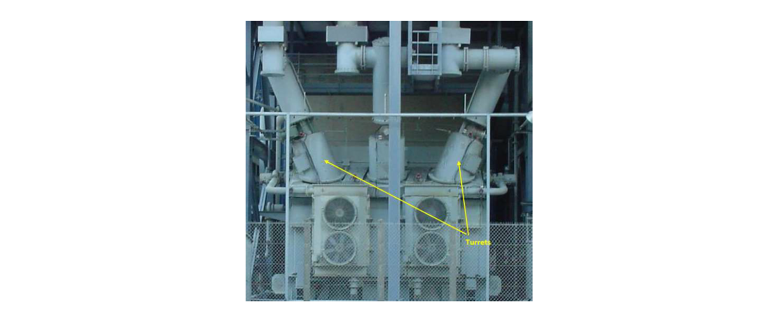
Figure 1 - Transformer bushings turrets
2. Transformer user specifications and international standards challenges
In EDF power transformer specifications, tank technology is not required, but the analysis of the mechanical design of the tank (wall thickness, welds, bolting, etc.) must be based on a validated, recognized, and approved method (Typically FE analysis and simulations). The vacuum resistance of the tank for oil treatments and the verification of the tank's tightness for the life of the transformers are covered by other clauses in the requirements.
In addition to the vacuum resistance requirements, the tank in its site installation conditions must be designed to maintain its sealing during overpressure due to internal arcing (high-energy dielectric breakdown), the energy of which depends on the voltage class of the transformer.
2.1. Requirements
- Above the specified pressure, the calculations shall allow to locate all the weak points in the tank (other than the pressure relief device).
- The Manufacturer shall propose measures to minimize oil leakage in case of tank rupture.
- The Manufacturer proposes measures to ensure that rupture does not lead to fire or damage to connecting parts.
2.2. Standards and practice guides
Apart from the CIGRE and IEEE publications, which do not serve as international standards, the only standard concerning the fire resistance of transformer tanks is IEEE Std C57.156-2016 [1]. The CIGRE A2.33 brochure [2] provides general recommendations for good practice in transformer fire safety. But without addressing the design criteria to respect for the tank and its metal worked components as well.
However, these documents do not provide guidelines on the requirements and methods for verifying the design regarding internal arc withstand of transformer tank and its components. Transformer users and manufacturers need a new standardization or revision to harmonize the IEEE, CIGRE and IEC approaches. In September 2022, CIGRE SC A2 Transformers and Reactors set up a Task Force entitled: Power Transformer Tank Specification for Passive Protection Against Internal Arc. The objective of this TF is to produce a Position Paper to support the international standards.
3. Manufacturer and Utility work carried out
The objective is to respond to EDF specific request for a solution to be implemented rapidly on the HV equipment. The 570 MVA transformer installed in SF6 power station with Oil/SF6 bushings would present a safety risk and the unavailability of the unit in the event of an internal arc fault of bushing.
So, we are targeting in the present work to design a test, to understand and control the overpressure generated by the internal arc in turret or another compartment fitted to the transformer tank. The HV bushing turret filled with oil is a critical component. It will be fitted with a protection device using pressure relief valves. The effectiveness of such a solution needs to be verified by a full-scale test on a prototype, under conditions as close as possible to the operating environment. The aim of this work is to validate this industrial solution, to ensure its effectiveness and the feasibility of its implementation in the field. At the same time, the data collected through measurements will allow to analyze the mechanism of generating high overpressure through the internal arc and the operation of the turret protection. This data will be useful for future simulations works.
The plan is as follows:
- Share and analyze the consequences of the failure of an Oil/SF6 bushing installed in its turret.
- Develop a representative test of the fault at the origin of the damages.
- Define the protocol and specification for the short-circuit test.
- Define the assignment of tasks and responsibilities for supplies.
- Manufacture and preparation of components and instrumentation
- Risk analysis
- Carrying out the test
- Analyzing and using the test results
4. Data for the internal arc withstand of the turret test specification
The analysis of the hatch degradations resulting from the Oil/SF6 bushing failure, shows that the rupture strength of its bolts assembly can be estimated by calculation. As shown in Figure 2, the internal arc originated on the oil-side on the immersed lower part of the bushing in the vicinity of the inspection hatch (hole man access). The high overpressure resulted in the rupture of the bolts and the projection of the hatch plate. EDF Calculations estimated the pressure in the turret required to pull the hatch door is about 53 to 63 bar. Using a rough estimate from CIGRE [2] and considering the turret dimensions, if we assume that the overpressure evolved between 0 and 60 bar with an energy between 1.5 MJ and 5 MJ.
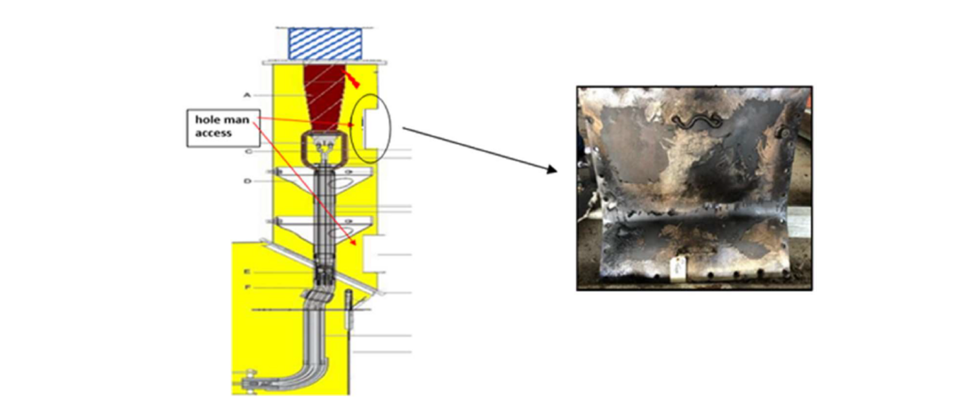
Figure 2 - Failure location in the transformer turret and inspection hatch plate damages
5. Test circuit description
The test consists of achieving an internal fault using a spark gap (machined rod extremities) immersed in oil filling the turret. The fault located in front of the inspection hatch causes a dynamic overpressure pushing on the latter. The energy targeted in the test is estimated between 2.5 MJ and 5 MJ.
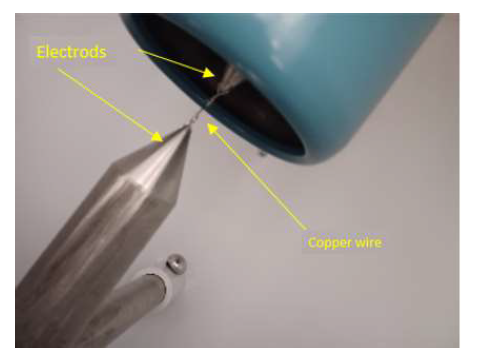
Figure 3 - Electrodes gap for the arc defect
To be as close as possible to operating conditions without compromising the safety and integrity of the test equipment, the prototype, Figure 4, to be tested will use a dry bushing (RIS resin and synthetic material type) so as not to interfere with the expected results.
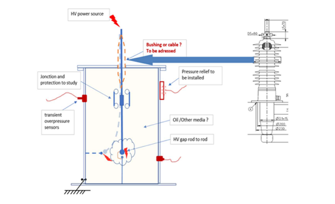
Figure 4 - Test set up principle
5.1. Test parameters specification
The short-circuit current, voltages to be tested and the dimensions of the electrode gap are decisive for the internal arc energy to be obtained. The specified values are:
- Short-circuit current of 40kArms. The current calibration is given in Figure 5.
- Fault duration of 150ms.
- Voltage supply of 30kV
The arc energy to reach is evaluated to 5.4MJ for an arc voltage of 1kV.
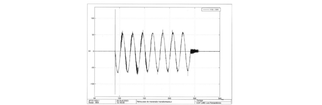
Figure 5 - Short circuit current calibration
The work led to the design, the manufacture and the instrumentation installation of the test set-up using an equipped bushing turret prototype filled with 1 400 liters of mineral oil. Two overpressure protections (Pressure Relief Device) are fitted to the hatch plate to limit the overpressure caused by the internal arc. The internal arc representing the fault is produced by a suitable spark gap immersed in the oil. The following illustration gives an overview of the assembly that was tested. Figure 6 gives an overview of the prototype to be tested, equipped with its bushing, the PRDs mounted on the inspection hatch plate and a plastic tank for collecting the oil expelled via the two protective devices.
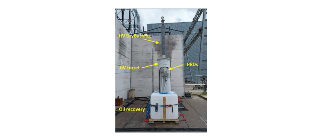
Figure 6 - Test set up before the test
5.2. Description of the instrumentation
Two transient pressure transducers were installed on the top and the bottom on a vertical line of the cylindrical turret. The two piezoelectric sensors measure dynamic pressure over the range of 0 to 35 bar. Other sensors are used and described in the Figure 7.
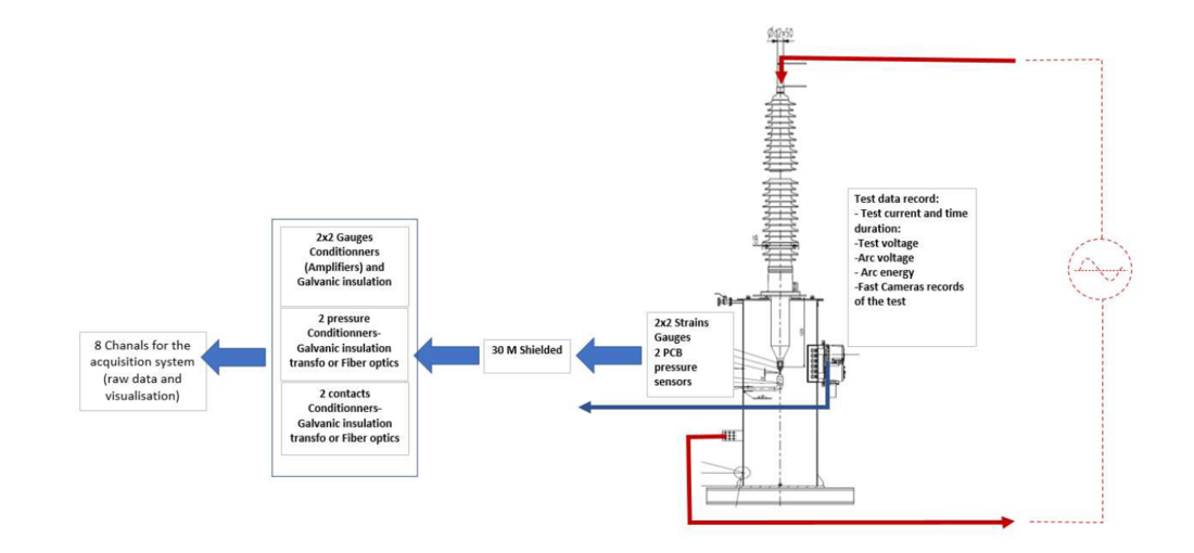
Figure 7 - General view of the instrumentation
6. Test results
To recall the stages of the overpressure process due to the arc:
- → Breakdown of the dielectric strength in the oil between electrodes (spark gap tips) and initiation of the high-energy arc in the turret between tips.
- → Temperature increase in the around arc, which vaporizes the oil and produces hydrocarbon gases that transform into plasma.
- → Bubble formation and increase in pressure around the arc under the hydrostatic pressure of the oil, which opposes the expansion of the bubble.
- → A mechanical wave is generated to propagate at low speed through the oil towards the metallic envelop.
- → Reaction of the rank and its protections.
7. Test result analysis
As shown in figure XX, for the full test, the measured parameters comply with the specified requirements. An arc voltage of 700 V was measured for a calculated energy of 3.5 MJ (integration of the measured current and duration). The values achieved during the test are summarized in Table 1.
Test | Root means square current | duration | Arc voltage | Arc Energy calculated |
|---|---|---|---|---|
1001 | 40,9 | 149,2 | 676,6 | 3,54 |
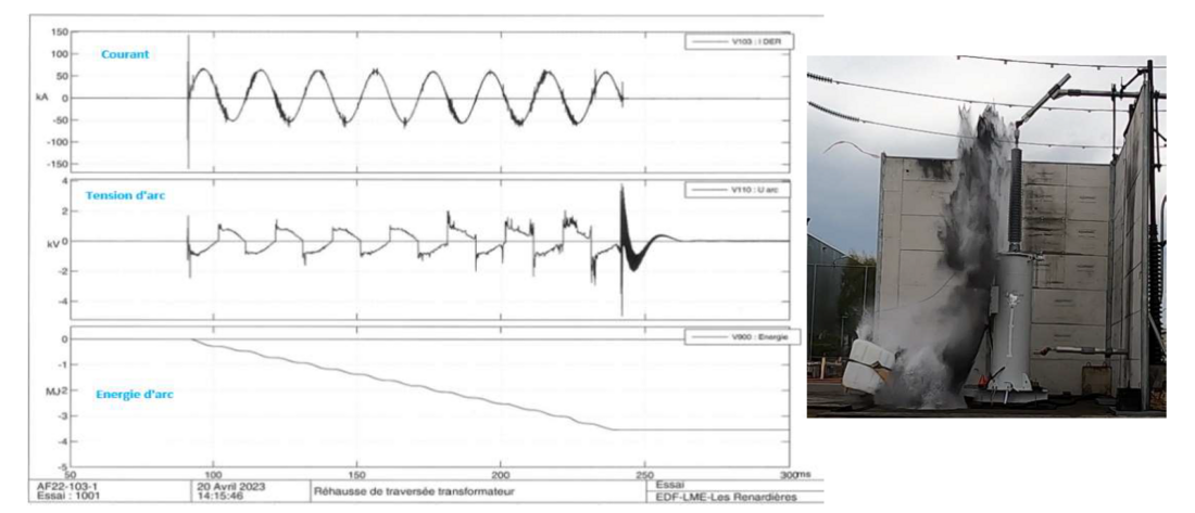
Figure 8 - Record of measured fault current, measured arc voltage and arc energy
For a short-circuit current of 41 kA maintained over 150ms, the two PRDs tripped respectively at 4 and 4.2 ms, as illustrated Figure 9, limiting the dynamic overpressure in the turret. With an arc energy of 3.54 MJ developed during the test, the peak dynamic pressure measured was limited to 17.5 bar and the static pressure measured on average was around 12 bar in the tested turret. This suggests that the overpressure can reach much higher values than those measured in the absence of PRDs
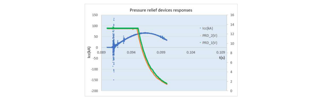
Figure 9 - Tripping of the PRDs at the first half fault current cycle
On post-test inspection, neither fire start-up was observed, nor permanent deformation of the turret was detected.
The process of internal overpressure resulting from the internal arc comprises 3 phases:
- a fast increase of the pressure
- a transient pressure spik.
- an oscillating permanent pressure build-up
Knowing the arc voltage and L its length of 2 cm, the empirical relationship (Varc= 55.L.P0.5) given in the CIGRE document [3] allows to estimate an absolute pressure of the gas bubble of the order of 37.8 bar. The peak pressure and the oscillating pressure are temporally correlated with the duration of the fault. Figure 10 plot the dynamic pressures measured in the cylindrical turret and their changes as a function of the short-circuit fault duration.
At the top of the turret with sensor P1, a peak overpressure of 10.8 bar was measured at the start of the fault and reached 11.8 bar 50 ms before the arc fault was extinguished. At the bottom of the turret, measurements with the P2 sensor were 15 bar to 17.5 bar at the start of the fault sequence and reached 12 bar after 100 ms. The CIGRE brochure states that locally, an immersed transformer could be subjected to a local pressure of 14 bar under an arc of 2.5 MJ. The measurements achieved in our test show that under 3.5 MJ, we reached some local pressure peaks of 15 and 17.5 bar.
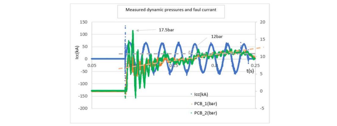
Figure 10 - Measured dynamic pressure during the fault current supply
It is important to note that the overpressure peaks due to the internal arc can only be held by a transformer tank for a few milliseconds and that rupture occurs if the static pressure limit is reached and lasts for more than a few milliseconds or, in the best cases, a few tenths of a second. As a reminder, the operating times for electrical protection are about 70 to 80 ms for the network side circuit-breaker to open. On the other hand, if there is no circuit-breaker on the generator side, the risk of continuing to supply the fault depends on the inertia of the generator (may exceed a few seconds).
Considering the measurements of the two transient pressure sensors located at different area in the turret, the kinetics of the pressure rise, respectively 10.8 bar in 2 ms (5000 bar/s) and 17.5 bar in 2 ms (8500 bar/s) raise questions about the absorption of the high pressure over the first 2 milliseconds. These values are consistent with CIGRE information, which indicates values of 100 bar/s to 5000 bar/s. But according to Figure 11 it’s clearly observed that the mechanical wave reached the first sensor which is the closest to internal arc, and 2 ms later, the second sensor start to detect the pressure wave. This is compliant with the distance between sensors of 1.7 m and the pressure wave propagation velocity in oil about 1400-1500 m/s. The compressibility of the oil and the flexibility of the turret may have played a role in this energy absorption. The characterization of the dynamic overpressure shows that more investigations is required to master the pressure wave propagation and its wall reflection as shown in Figure 11.

Figure 11 - Characterization of the measured dynamic overpressures in the turret
8. Conclusion
The results of the investigations presented in this document shed light on the understanding of the internal arc withstand of transformer metal worked components. For maintenance and operation, a retrofit solution to mitigate the risk of internal arcing in HV bushing turret has been validated by verifying its effectiveness with a real electrical test. This retrofit solution has been simulated and the retrofit modification doesn’t influence any other function or performance of the transformer. Even the high voltage design of the turret – bushing arrangement has been evaluated and fulfill all necessary requirements.
A test specification has been developed and drawn up in collaboration between EDF as a utility and the manufacturer SIEMENS-ENERGY. The test of this retrofit solution for protecting EHV oil/SF6 bushings turret from explosion proofed the effectiveness. In the event of a bushing failure, a set of pressure relief device will prevent the turret from rupture and reduce the risk of fire.
In the case of oil/SF6 bushings turrets, this protection by means of PRDs significantly limits the dynamic overpressure, but the permanent pressure level must be considered in the design. In addition, mechanical robustness of system should be regarded to prevent it from degradation, from the risk of ejection and to ensure a rapid closure of the valve to limit the amount of oil expelled.
More generally, in the case of cylindric bushing turrets, cable boxes and load changer compartments, this protection may significantly limit dynamic overpressure, but a permanent pressure level must be considered in the design. And with all experience and with tests verified simulations, transformer tanks can be designed accordingly. Therefore, a safe and environmentally friendly solution with reduced risk of fire in case of an internal arc due to a bushing failure is now available.
References
- IEEE Std C57.156-2016: Guide for Tank Rupture Mitigation of Liquid Immersed Power Transformers and Reactors
- CIGRE Technical Brochure 537: “Guide for Transformer Fire Safety Practices”, Juin 2013
- EDF R&D Renardières Lab: Internal Test report RAP-AF22-103-1-V2