Small-Signal Analysis Benchmarking of Three Control Algorithms for Grid-Forming Inverters
Authors
M. CARREÑO, M.A. RIOS - Department of Electrical and Electronics Engineering, School of Engineering, Universidad de los Andes, Bogota, Colombia
O. GOMIS-BELLMUNT - Department of Electrical Engineering, Universitat Politècnica de Catalunya, Barcelona, Spain

Summary
Grid-forming inverters behave as controlled voltage sources in contrast to grid-following inverters that behave as controlled current sources. However, several control strategies have been proposed for grid-forming inverters. This paper examines the small-signal stability performance of three grid-forming control algorithms in a test grid that includes a synchronous generator, a grid-following inverter, and a grid-forming inverter. The examined algorithms are: Virtual Synchronous Machine, Droop control, and Virtual Oscillator Control. The results suggest that only the Virtual Synchronous Machine algorithm has a high participation in one of the modes of the system. On the other hand, the grid-following inverter has a high participation in the oscillation modes, particularly through the Phase Locked Loop and the inner current control.
Keywords
grid-following, grid-forming, VSC, small-signal analysis, modal analysisNomenclature
AVR Automatic Voltage Regulation
GFL Grid Following VSC
GFM Grid Forming VSC
HVDC High Voltage Direct Current
PLL Phase-Locked Loop
PSS Power System Stabilizer
SM Synchronous Machine
SSSA Small-Signal Stability Analysis
VCI Voltage Controlled Inverter
VOC Virtual Oscillator Control
VSC Voltage Sourced Converter
VSG Virtual Synchronous Generator
VSM Virtual Synchronous Machine
1. Introduction
Voltage Sourced Converters (VSCs) transform DC power to AC power in HVDC stations, photovoltaic and wind power plants, and battery storage plants. The control algorithm implemented in a VSC determines its response to perturbations such as short-circuits, generator or line tripping, etc. The standard control algorithm is known in the academic community as Current Vector Control and VSCs with this control are referred to as Grid-following VSCs (GFL VSCs). The name alludes to the fact that GFL VSCs regulate their current output but “follow” the voltage angle imposed by the grid at its terminals. Thus, a GFL VSC behaves like a controlled current source. However, GFL VSCs might fail when their point of interconnection is electrically far from synchronous condensers or generators [1]. This is the case of GFL VSCs connected in the tail of a radial network or in an islanded network [2].
Unlike GFL VSCs, Grid-forming VSCs (GFM VSCs) do not regulate the current output but the voltage output of the device. Therefore, a GFM VSC behaves like a controlled voltage source. This makes it ideal for situations where the GFL control could fail, such as islanded and radial networks. Some researchers think that grid-forming VSCs are the key to unlock the penetration of more energy from renewable sources [3], [4]. In this paper, the GFM VSCs are intended to be always interconnected with other generation and not islanded.
Several control algorithms have been proposed for GFM VSCs. Among these are: Virtual Synchronous Generator/Machine (VSG/VSM), droop control, Power Synchronization Control (PSC), Enhanced Direct Power Control (EDPC), Voltage Controlled Inverter (VCI), Virtual Oscillator Control (VOC), and Matching control, among others [5], [6]. Inverter manufacturing companies are transitioning to the production phase of these algorithms [7], [8], [9]. This along with the success of small implementations suggests that future power grids will include synchronous machines, GFL VSCs, and GFM VSCs.
One of the tools that traditionally has been used to assess the stability of a power network is Small-Signal Stability Analysis (SSSA). This tool gives information on the modes of oscillation of the system and the relative participation of control loops and physical elements.
Table 1 summarizes the contributions of papers that study the SSSA of power systems with synchronous machines and VSCs operating simultaneously. Most of the studies are performed on small systems of three or four busbars. Moreover, only two papers deal with the simultaneous operation of synchronous machines (SM), GFL VSCs and GFM VSCs.
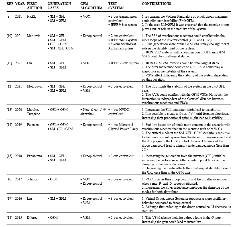
Table 1 - Previous research
To the best knowledge of the authors, the algorithms VSM, droop control, and VOC have been examined individually but have not been benchmarked simultaneously with identical tests and identical networks. This paper intends to provide this benchmarking using the IEEE 9-bus system as test grid. Moreover, the simultaneous operation of a synchronous machine, a grid-following VSC and a grid-forming VSC is examined to account for a more realistic operation scenario.
The benchmarking provides useful data for control engineers who face challenges such as choosing one algorithm over the others, and sometimes correcting issues concerning small-signal stability through the retuning of the control parameters.
2. Small-signal stability analysis
In SSSA a nonlinear system is linearized around an operation point and diagonalization is applied to find the fundamental dynamics of the system [19]. A general description of the process is presented in Fig. 1.
In this paper the focus is on slow dynamics and the switching of the converters is neglected. Therefore, the assumption of network modelling in fundamental frequency is reasonable and instead of generating the matrices by hand the software PowerFactory by DigSilent was used for the Small-Signal Stability Analysis.
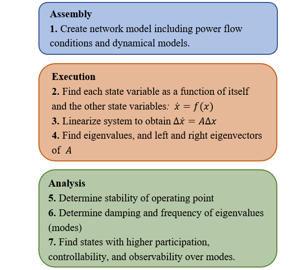
Figure 1 - Steps of SSSA
Step 7 of Fig. 1 merits some explanation. The right eigenvectors determine the share of a certain mode in a particular state variable (observability). The left eigenvectors determine the share of a certain state in a particular mode (controllability). However, these two vectors depend on units and scaling. Thus, a better, dimensionless measure are participation factors, which are calculated from the right and left eigenvectors. These factors measure the participation of states in modes. Therefore, since each state variable is part of a dynamic model, it is possible to match approximately each eigenvalue with a control loop or physical behavior in the network.
3. Dynamic models
The dynamical models are at the core of SSSA. The assumptions and characteristics of our models are:
- They are RMS, positive sequence models. This implies that the studies are focused on the average behavior and not in the instantaneous phenomena.
- They are simple models. Attempts have been made to reduce the dynamic models to the most fundamental blocks. Therefore, “direct” GFM control schemes have been chosen instead of cascaded current-voltage loops (also known as inner loops). Some research shows that the latter scheme is more difficult to tune and more prone to instability [20]. Saturation logic was avoided for GFL and GFM models since we are interested in the post-fault behavior, when the saturators do not operate anymore. This approach was also taken by Markovic [10], Lin [11], and Pattabiraman [15]. The current vector control has also been simplified and the dq decoupling has been neglected. The reason is that a current source behavior was achieved with two PI compensators and that was considered enough. The function of the decoupling is obtaining a current source with a first-order behavior [21], but that can be neglected in the search for oscillatory modes.
Fig. 2 shows the current vector control for GFL VSC adapted from [22], and the three algorithms for the GFM VSC are shown in Fig. 3, based on [23], [24],[25]. In the diagrams, fref is the frequency shift of the reference generator, the SM. It is subtracted in all models for accuracy in RMS positive-sequence studies. Signals Pcmd and Qcmd model commands from the outer loop control, and signals with subscript meas represent measurements while subscript ref stands for reference.
- The synchronous machine model includes rotor speed (speed), rotor angle (phi), field flux (psifd), and direct and quadrature fluxes of a single damping circuit (ψ1d, ψ1q). Additional information on the standard model is found in [26].
- A modified IEEE Type 1 excitation loop was connected to the synchronous machine. This exciter is named Mag-A in this study and its state variables are xr, xa, xe, and xf. For more information on the dynamic model see [27] and [28]. A governor was not considered. For the VSCs, a standard voltage controller for the outer loop was implemented, as shown in Fig. 4.
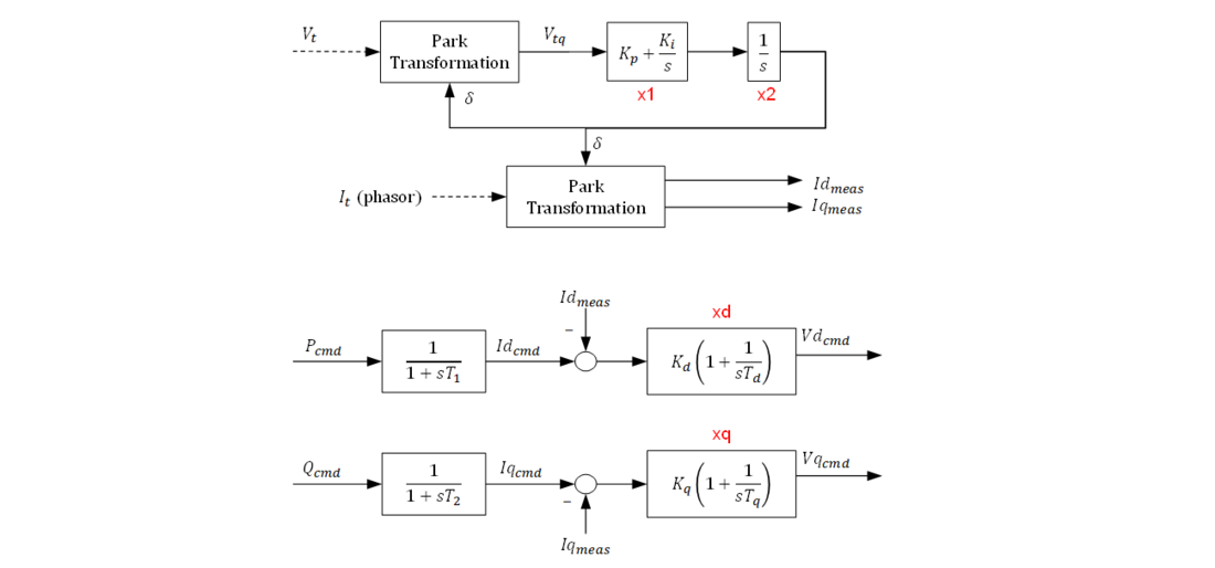
Figure 2 - Current Vector Control
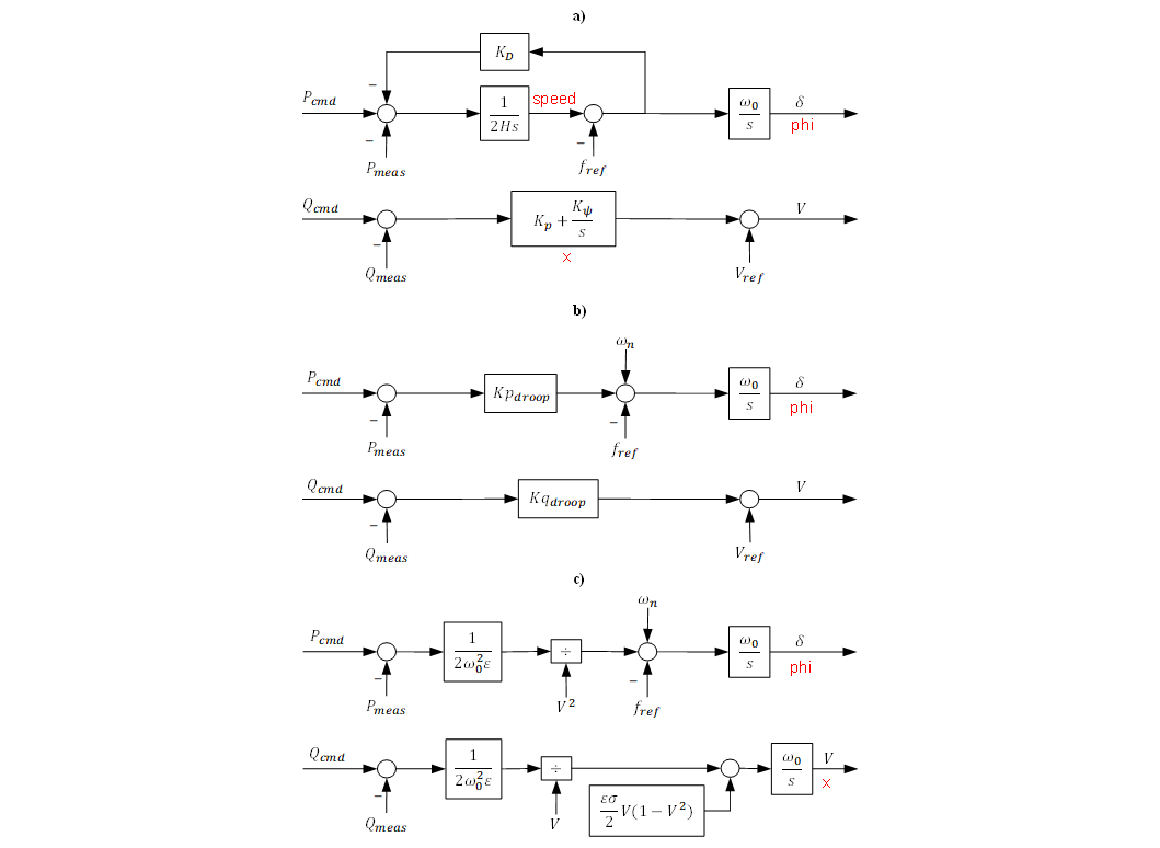
Figure 3 - a) Virtual Synchronous Machine, adapted from [23]. b) Droop control, adapted from [24]. c) Virtual Oscillator Control, adapted from [25]

Figure 4 - Plant-level voltage control applied to the GFM and GFL VSCs
4. Test System
The test system is a modified version of the WSCC 9-bus system proposed by Anderson and Fouad in [29]. Generators G1 and G3 have been replaced with a GFL VSC and a GFM VSC, respectively; as Fig. 5 shows. Additionally, G1 and G3 are now interconnected to the bulk power system through 230 kV transmission lines shown in red in Fig. 5. These transmission lines were added to find the effect of increasing the electrical distance of the inverters in the SSSA of the system.
An important feature of the network model is the modelling of the DC side of the VSC. In EMT studies the DC side is usually modelled with a capacitor and a current source representing the battery or photovoltaic cells. However, in this software the DC side was modelled with ideal voltage sources. Consequently, from a circuit perspective, the current capability and available energy of the VSCs is infinite.
The power flow condition and the equilibrium of the dynamic system, is identical to the one studied in the original reference by Anderson and Fouad [29].
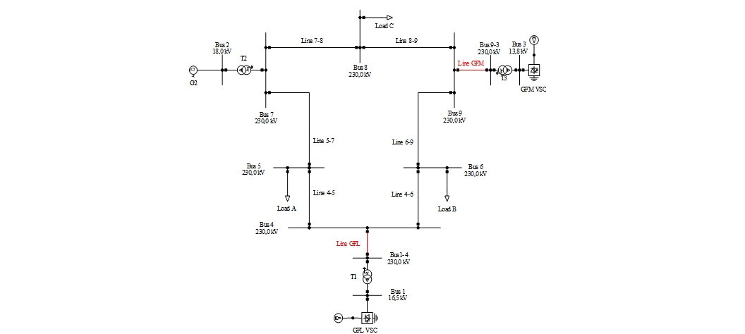
Figure 5 - Modified WSCC 9-bus System
5. Description of the tests and results
Two tests were conducted to investigate the influence of control parameters and network conditions in the SSSA of the network.
5.1. First test – analysis of the original equilibrium
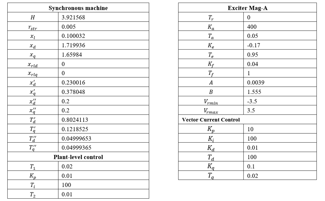
The operation point depends on the load flow and the parameters of the dynamic models. The reference operation point, or original equilibrium, corresponds to the original load flow and the parameters presented in the Appendix. The SSSA was performed for four cases. In the Base case all generators are SM, while in the other three cases G1 is a GFL VSC and G3 a GFM VSC. The name of the cases is thus assigned depending on the GFM algorithm tested.
From all the eigenvalues obtained through SSSA, only those that were complex numbers with non-zero imaginary part were saved while negative reals were excluded. A mode of oscillation that originated from the PI blocks of the current control was also excluded because in real implementations, this loop does not participate in oscillatory dynamics due to dq decoupling.
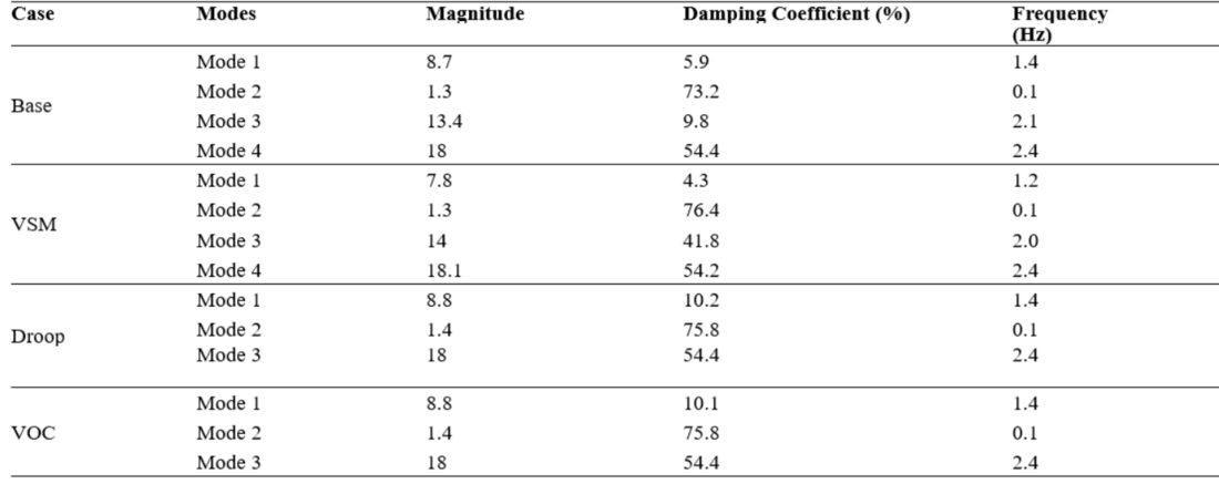
Table 2 - Oscillatory modes in base case and study cases
The magnitude, damping coefficient, and frequency of the modes of oscillation is shown in Table 2. Also, to gain insight in the influence of the dynamic models in the modes of oscillation, the participation factors were obtained and are displayed in Fig. 6 to Fig. 9. In these diagrams, the participations of the states are normalized to sum 100% in each row. For those states with a participation higher than 10% the name of the state variable is displayed.
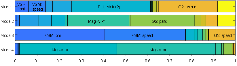
Figure 6 - Participation factors of the modes in the Base case.

Figure 7 - Participation factors of the modes in the VSM case
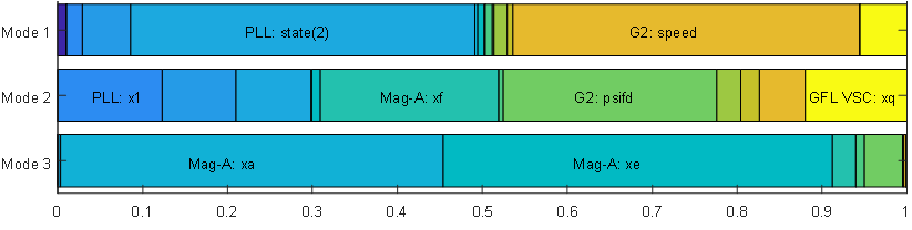
Figure 8 - Participation factors of the modes in the droop case
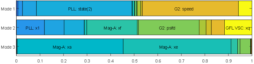
Figure 9 - Participation factors of the modes in the VOC case
The findings of this test are synthetized as follows:
- Modes 1 and 3 in the base case are electromechanical modes. This can be concluded from their frequency, their relatively small damping, and the large participation of the rotors of the generators (Fig. 6).
Mode 4 has a frequency close to the previous two; but it is highly damped and comes exclusively from the exciter of G2. In fact, in all cases Mode 4 remains practically unchanged and does not interact with the loops of G1 and G3.
- Modes 1 and 3 in the VSM case are also electromechanical modes, even when only Generator 2 has “mechanical” components. In Mode 2, the angle dynamics of the three generators interact, while in mode 4 mainly the virtual rotor of the VSM interacts with the rotor of G2. The damping is higher in Mode 4, and the reason might be attributed to the smaller participation of the rotor of G2.
Mode 2 is very slow, with a frequency of 0.1 Hz, and is influenced mainly by the damper circuits of the rotor and the exciter. However, it is highly damped, which makes it of less interest.
- In the Droop and VOC cases only one “electromechanical” mode is present, which corresponds to Mode 1, the one originated by the interaction of the PLL in G1 and the synchronous machine G2. Mode 2 previously analyzed is also present, practically unchanged.
5.2. Second test – Variation of electrical distance
GFL VSCs are prone to fail when separated by a large electrical distance to a “strong” voltage source such as a synchronous machine. In the previous test the distance of the interconnecting transmission lines was zero; but in this test the distance of the interconnection lines is swept from 0 km to 200 km and the movement of the modes is tracked. Instead of plotting the modes in the complex plane, it was decided to only plot the evolution of the damping coefficient as the distance changes. The reason is that damping is usually a more useful metric and instability is easily identified by a negative value (ζ<0).
Fig. 10 shows the displacement of the modes when the electrical distance of the GFL VSC increases. The most important result is that in the VSM case Mode 1 falls in the unstable region while in the other two cases it does not. The explanation lies in Fig. 7 that clearly shows the participation of the “virtual rotor” in Mode 1. This influence is not present in the other two cases, which implement algorithms in the GFM VSC that do not have two integrations (second order systems).
Mode 4, the other “electromechanical” mode in the VSM case, remains unchanged. This can be attributed to the small participation of the PLL. Therefore, the natural conclusion is that, with an increase the electrical distance of the GFL VSC the Virtual Synchronous Machine algorithm implemented in the GFM VSC may need to be retuned. This is evidence that the implementation of VSM or VSG algorithms must be carefully studied, and preference can be given to Droop control and VOC algorithms.
Fig. 11 shows the displacement of the modes when the electrical distance of the GFM VSC increases. Now, Mode 1 and Mode 3 move, but they seem to become more damped as the distance increases. This is evidence that GFM VSCs are more robust to conditions of high electrical distance to synchronous generators. Nonetheless, the reasons for the increase in the damping can be the topic of another research.
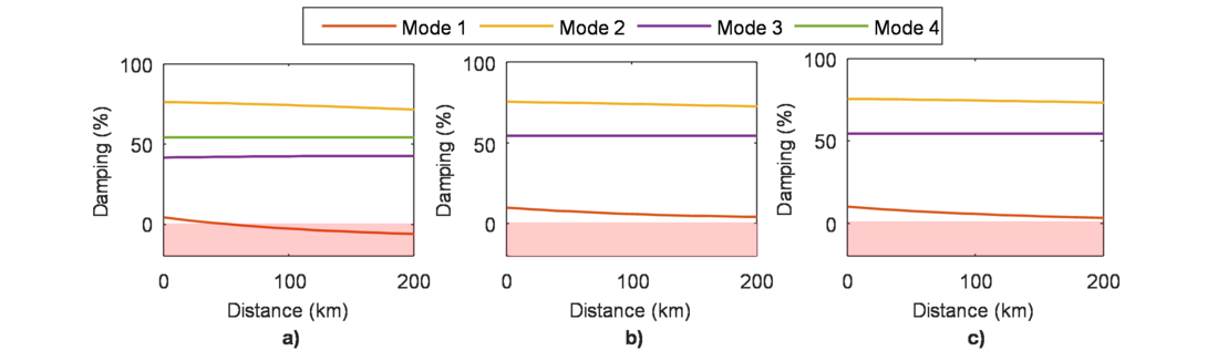
Figure 10 - Increase in length of line interconnecting the GFL VSC. a) VSM, b) Droop control, c) VOC
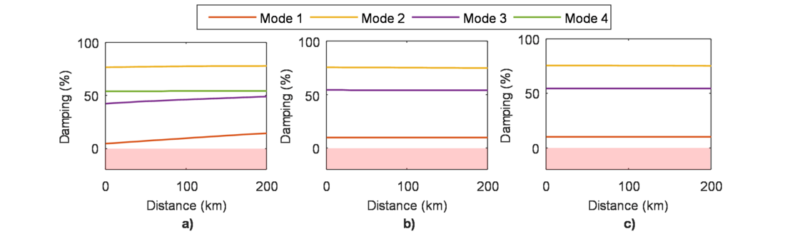
Figure 11 - Increase in length of line interconnecting the GFM VSC. a) VSM, b) Droop control, c) VOC
6. Conclusion
In this paper we have studied the modes of oscillation that appear in a futuristic power network that integrates three technologies of generation: synchronous machine, GFL VSCs, and GFM VSCs. Moreover, three different algorithms were tested for the GFM VSC to compare their performance in SSSA, achieving a benchmarking that, to the best knowledge of the authors, has not been done before.
Emphasis has been given to the “electromechanical” modes, which are slow modes with relatively small damping influenced in great part by the physical characteristics of the synchronous machine.
Synthetizing the information provided by the tests in the previous sections, the following conclusions follow:
- Introducing a VSM algorithm in the GFM VSC produces two modes of oscillations. One of these modes is influenced by all three generators, while the other is only influenced by the GFM VSC and the SM. The Mode influenced by the three generators is sensible to the increase in the electrical distance of the GFL VSC. Therefore, it is recommended to carefully study the introduction of a GFM VSC with a Virtual Synchronous Machine or Virtual Synchronous Generator algorithm.
- Some previous researches have introduced the question of how significant is the influence of the exciter of the SM, and the outer voltage loop of the inverters in the small-signal stability of the system. In this paper it was shown that the exciter adds an oscillation mode, but it does not interact with the other generators and remains unchanged in all cases. On the other hand, the outer voltage control barely participates in the modes.
- The Droop and VOC algorithms are very different. One is very simple and linear, while the other is nonlinear. However, they share a fundamental characteristic, the lack of two integrations in the angle loop. This might be the reason why in the SSSA they are so similar in all tests. This is a useful consideration for the design of GFM algorithms.
Future work on this subject could include the following:
- Not only considering “direct” GFM algorithms, but also algorithms with a cascaded inner loop.
- Considering a larger grid, with more GFM generators possibly integrating different control algorithms.
- Adding dynamic simulations as validation of the results from SSSA. In this paper time-domain validations were not introduced due to page number restriction.
Finally, it is recognized that small-signal stability analysis has a limited scope, and a full assessment of the stability of a network with GFL and GFM VSCs must include other studies such as instantaneous dynamic simulations (EMT studies), RMS dynamic simulations and could even include newer tools such as impedance models.
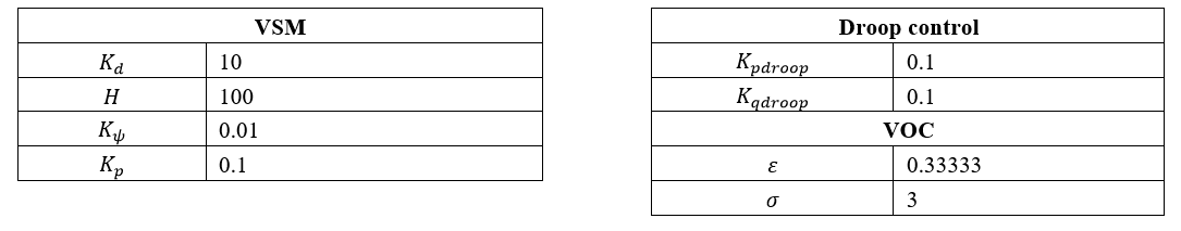
7. Appendix : Parameters
8. References
- B4.62 CIGRE Working Group, "Connection of wind farms to weak AC networks - Brochure 671," CIGRE, Paris, 2016.
- Q. Hu, L. Fu, F. Ma and F. Ji, "Large Signal Synchronizing Instability of PLL-Based VSC Connected to Weak AC Grid," IEEE Transactions on Power Systems, vol. 34, no. 4, pp. 3220-3229, 2019.
- J. Matevosyan, B. Badrzadeh, J. Prevost, E. Quitmann, D. Ramasubramanian, H. Urdal, S. Achilles, J. MacDowell, S. Huang, V. Vital, J. O'Sullivan and R. Quint, "Grid Forming Inverters: Are They the Key for High Renewable Penetration?," IEEE Power & Energy Magazine, vol. 17, no. 6, pp. 89-98, 2019.
- R. Lasseter, Z. Chen and D. Pattabiraman, "Grid Forming Inverters: A Critical Asset for the Power Grid," IEEE Journal of Emerging and Selected Topics in Power Electronics, vol. 8, no. 2, pp. 925-935, 2020.
- R. Rosso, X. Wang, M. Liserre, X. Lu and S. Engelken, "Grid-Forming Converters: Control Approaches, Grid-Synchronization, and Future Trends—A Review," IEEE Open Journal of Industry Applications, vol. 2, pp. 93-109, April 2021.
- P. Unruh, M. Nuschke, P. Strauß and F. Welck, "Overview on grid-forming inverter control methods," Energies, vol. 13, no. 10, 2020.
- J. Glassmire, S. Cherevatskiy, G. Antonova and A. Fretwell, "Using Virtual Synchronous Generators to Resolve Microgrid Protection Challenges," in 2021 74th Conference for Protective Relay Engineers, CPRE 2021, College Station, TX, USA, 2021.
- Y. Lin, B. Johnson, S. Dhople, F. Bullo, P. Chapman, V. Purba, S. Jafarpour, G.-S. Seo, H. Villegas-Pico, N. Ainsworth, M. Rodriguez, M. Khan, J. Eto, A. Ellis, J. Flicker, B. Pierre and R. Lasseter, "Final Technical Report: Stabilizing the Power System in 2035 and Beyond: Evolving from Grid-Following to Grid-Forming Distributed Inverter Controllers," NREL, Golden, CO, 2021.
- O. Schömann, H. Sadri, W. Krüger, T. Bülo, C. Hardt, R. Hesse, A. Falk and P. R. Stankat, "Experiences with Large Grid-Forming Inverters on Various Island and Microgrid Projects," in 4th International Hybrid Power Systems Workshop, Crete, Greece, 2019.
- U. Markovic, O. Stanojev, P. Aristidou, E. Vrettos, D. Callaway and G. Hug, "Understanding Small-Signal Stability of Low-Inertia Systems," IEEE Transactions on Power Systems, vol. 36, no. 5, pp. 3997-4017, Sept. 2021.
- Y. Lin, G.-S. Seo, S. Vijayshankar, B. Johnson and S. Dhople, "Impact of Increased Inverter-based Resources on Power System Small-signal Stability," in 2021 IEEE Power & Energy Society General Meeting (PESGM), Washington, DC, USA, 2021.
- R. Mourouvin, J. C. Gonzalez-Torres, J. Dai, A. Benchaib, D. Georges and S. Bacha, "Understanding the role of VSC control strategies in the limits of power electronics integration in AC grids using modal analysis," Electric Power Systems Research, vol. 192, no. 106930, pp. 1-15, March 2021.
- J. Martínez-Turégano, S. Añó-Villalba, S. Bernal-Perez, R. Peña and R. Blasco-Gimenez, "Small-signal stability and fault performance of mixed grid forming and grid following offshore wind power plants connected to a HVDC-diode rectifier," IET Renewable Power Generation, vol. 14, no. 12, pp. 2166-2175, 2020.
- L. Petersen, F. Iov and G. C. Tarnowski, "A model-based design approach for stability assessment, control tuning and verification in off-grid hybrid power plants," Energies, vol. 13, no. 1, pp. 49-75, 2020.
- D. Pattabiraman, R. H. Lasseter and T. M. Jahns, "Comparison of Grid Following and Grid Forming Control for a High Inverter Penetration Power System," in 2018 IEEE Power & Energy Society General Meeting (PESGM), Portland, OR, USA, 2018.
- B. Johnson, M. Rodriguez, M. Sinha and S. Dhople, "Comparison of virtual oscillator and droop control," in 2017 IEEE 18th Workshop on Control and Modeling for Power Electronics (COMPEL), Stanford, CA, USA, 2017.
- J. Liu, Y. Miura and T. Ise, "Comparison of Dynamic Characteristics Between Virtual Synchronous Generator and Droop Control in Inverter-Based Distributed Generators," IEEE Transactions on Power Electronics, vol. 31, no. 5, pp. 3600-3611, 2016.
- S. D'Arco, J. A. Suul and O. B. Fosso, "A Virtual Synchronous Machine implementation for distributed control of power converters in SmartGrids," Electric Power Systems Research, vol. 122, pp. 180-197, May 2015.
- P. Kundur, "Small-Signal Stability," in Power System Stability and Control, Palo Alto, California, McGraw-Hill, 1994, pp. 699-822.
- W. Du, Z. Chen, K. P. Schneider, R. H. Lasseter, S. P. Nandanoori, F. K. Tuffner and S. Kundu, "A Comparative Study of Two Widely Used Grid-Forming Droop Controls on Microgrid Small-Signal Stability," IEEE Journal of Emerging and Selected Topics in Power Electronics, vol. 8, no. 2, pp. 963-975, 2020.
- A. Egea-Alvarez, A. Junyent-Ferré and O. Gomis-Bellmunt, "Active and Reactive Power Control of Grid Connected Distributed Generation Systems," in Modeling and Control of Sustainable Power Systems, Toledo, USA, Springer, 2012, pp. 47-83.
- D. Ramasubramanian, P. Pourbeik, E. Farantatos and A. Gaikwad, "Simulation of 100% Inverter-Based Resource Grids With Positive Sequence Modeling," IEEE Electrification Magazine, vol. 9, no. 2, pp. 62-71, 2021.
- A. Tuckey and S. Round, "Practical application of a complete virtual synchronous generator control method for microgrid and grid-edge applications," in IEEE 19th Workshop on Control and Modeling for Power Electronics, COMPEL, Padua, Italy, 2018.
- S. D'Arco and J. A. Suul, "Virtual synchronous machines - Classification of implementations and analysis of equivalence to droop controllers for microgrids," in Powertech Conference, Grenoble, France, 2013.
- M. Lu, S. V. Dhople and B. Johnson, "Benchmarking Nonlinear Oscillators for Grid-forming Inverter Control," IEEE Transactions on Power Electronics, vol. 37, no. 9, pp. 10250 - 10266, 2022.
- P. Kundur, "Synchronous Machine Representation in Stability Studies," in Power System Stability and Control, Palo Alto, California, McGraw-Hill, 1994, pp. 169-198.
- P. M. Anderson and A. A. Fouad, "Excitation Systems," in Power System Control and Stability, IEEE, 2003, pp. 233-308.
- P. M. Anderson and A. A. Fouad, "The Effect of Excitation on Stability," in Power System Control and Stability, IEEE, 2003, pp. 309-367.
- P. M. Anderson and A. A. Fouad, "The Elementary Mathematical Model," in Power System Control and Stability, IEEE, 2003, pp. 13-52.
Biographies
Miguel Carreño: received a degree in electrical engineering in 2019 and a M.Sc. degree in electrical engineering in 2022, both from Universidad de los Andes, Bogota, Colombia. He was a consultant engineer at GERS S.A.S. Currently, he is making his doctoral studies at the Department of Electrical Engineering, Universitat Politècnica de Catalunya.
Mario A. Rios: received a degree in electrical engineering in 1991 and a M.Sc. degree in electrical engineering in 1992, both from Universidad de los Andes, Bogota, Colombia. He received a Ph.D. degree in electrical engineering from INPG-LEG, Grenoble, France, in 1998, and a Doctoral degree in engineering from Universidad de los Andes, in 1998. He worked as a consultant engineer in ConCol (now WSP), Colombia, during 12 years. Also, he was a Research Associate at the University of Manchester (formerly, UMIST). Currently, he is Full Professor at the Department of Electrical and Electronics Engineering, Universidad de los Andes, Bogotá.
Oriol Gomis-Bellmunt: received the degree in industrial engineering from the School of Industrial Engineering of Barcelona (ETSEIB), Technical University of Catalonia (UPC), Barcelona, Spain, in 2001 and the Ph.D. degree in electrical engineering from the UPC in 2007. In 1999, he joined Engitrol S.L. where he worked as Project Engineer in the automation and control industry. Since 2004, he has been with the Electrical Engineering Department, UPC where he is a professor and participates in the CITCEA-UPC Research Group. Since 2020, he is an ICREA Academia researcher. In 2022, he co-founded the start-up eROOTS focused on the analysis of modern power systems. His research interests include the fields linked with electrical machines, power electronics, and renewable energy integration in power system.