Expanding smart grid capability using transmission lines – the formation of a Synergic Network
authors
B.N. AIRES, E. FERREIRA DA COSTA, J.B. ROSOLEM - CPQD, Brazil
A. DELLALLIBERA - Balestro, Brazil
C.A.M. DO NASCIMENTO - Cemig, Brazil
V. NAIDOO - EFLA, Norway

Summary
This work presents the concept and platform of Synergic Network (SN) using optical technology applied to Smart Grid digital transformation. The SN permits that energy and communications networks no longer operate independently but share infrastructure and provide higher quality services, operational efficiency, and optimized global investments in the expansion of electricity and optical fiber networks. The results of SN have been applied by CEMIG a Brazilian utility. The results presented herein eminate from fifteen years of research and development projects. Developments and field tests have been assisted in creating a new platform for planning, design, and construction of intelligent electrical networks that include broadband data communication and photonic and optical sensing technologies. This paper details the main elements and benefits of the first generation of SN. Furthermore, the paper details the field tests in the pilot projects and some sensing systems applied for Smart Grid, and a future view of the second generation of SN.
keywords
Transmission and Distribution Networks - FTTH - Hybrid Conductors - Optical Communications - Optical Fibers - Optical Sensors - PFTTH - Power industry - Smart Grid1. Introduction
The use of optical fiber in transmission and distribution networks for communications services has gradually recognized by energy industry experts as the next step in electrical network digitization[1][2]. Optical fiber is excellent for data transmission to meet Smart Grid's communication requirements. It also has benefits such as supporting broadband communications services and sensing. The optical phase conductor (OPPC) allowed for the combination of optical and electrical network into a single conductor. At the beginning of a decade of 2010, many works were developed with OPPC [3][10].
CEMIG and CPQD over the last 15 years have been investing in research and development (R&D) projects in transmission and distribution (T&D) asset monitoring, with the use of optical technology, both as a sensor element and for transmission data. In this context, the concept of Synergic Networks (SN) emerged using several devices executing functions. SN uses a hybrid conductor, i.e., metal part for conducting electric energy and a secondary part constructed with optical fibers for communication.
The initial challenge was acceptance of the OPPC technology in the energy industry. The hybrid conductor is designed with a stainless-steel tube placed in the central part of the conductor used to carry the fibers. Unlike OPGW cables that are grounded, the OPPC cables are energized, requiring special insulated voltage sensitive hardware to be installed to allow the communication fibers to be isolated from the power. Through the concept of Synergic Networks, new configurations for the |design and construction of electric power lines and optical fibers networks were required. The optical R&D projects were successfully deployed and are in operation at the UniverCemig trial site in Sete Lagoas City, Brazil. Three phases were done on of the Synergic Networks on 138 and 13.8 kV [11].
Another important investment that accelerated the application of SN in Brazil was support from the national optical industry. The first generation of optical phase conductor - OPPC (Linnet-OPPC; 1/0-OPDC; 4/0-OPDC; 50 mm2 cover-OPPC and steel 3/8-OPDC) were manufactured. The electrical/optical insulator and new connectors were developed.
The SN will facilitate the following technological developments:
- New generation of optical Smart Grid networks;
- Facilitate the infrastructure required by smart cities;
- Increase internet of things (IoT) use in the electric energy and broadband data communications sector;
- Generate fully digital management such as the integration of large-scale distributed generation in the electricity sector;
- Design a new generation of optical equipment and components, systems, and other intelligent sensors.
The concept of SN is realistic in a developing country like Brazil because of the many new infrastructure asset that must be built. The fact that where the aggregation of intelligence to the systems of management, operation, and automation of electric energy networks through intelligent networks are required will only occur concurrently with the expansion of the broadband data communications sector to its last mile. Thus, a plausive path to digitalization of T&D utilities can be envisaged in the medium and long term mainly in new and refurbish assets.
The objective of this article is to explore an innovative concept with the new platform through the digitalization of assets in Brazilian Utility Cemig, based on optical Smart Grid. The paper detailed the benefits of SN and its main elements, such as conductor with optical fiber embedded and its special accessories, such as insulators with optical fibers embedded and splice boxes. Furthermore, the paper detailed the field tests of three pilot projects at high, medium, and low voltage. Also, some sensing systems applied for optical smart grid are described.
2. The Concept
The concept of SN emerged within the platform of Smart Grid using purely optical technologies. Optical fiber is the best means of data transmission to meet communication requirements in the electrical sector (high broadband, low latency, no RF interferences, intrinsic cybersecurity, etc.) and is a way to expand optical fibers that can bring many other benefits with tangible and intangible gains to utilities and society. Like other areas of knowledge, the evolution of electric energy and data communication technologies appear with breakthrough innovations to be fundamental to accelerate the economic and social revolution in developing countries like Brazil. The central motivation for development of the SN concept showed the direct relationship between users of electric energy and broadband data communications to compose the new topology of networks of the future. The SN has consolidated an innovative network that can achieve a high level of synergy between all stakeholders.
3. The Synergic Networks
The SN was successful when a theoretical concept was applied in the form of a full-scale test at the UniverCemig site in Brazil. The synergistic network integrated the functions of optical fibers used for broadband data communications, and the possibility of sensing the various elements of the electricity network on the same platform, where these elements are cooperative with each other. The synergistic networks when applied to the data communications sector will provide a new opportunity for the expansion of broadband networks through the concept of last mile fiber. The new SN topology is different from the traditional Fiber to the Home (FTTH) telecommunications and different from the Power Fiber to the Home (PFTTH) technologies [3]-[10]. The main difference is in the installation of its optical fiber in direct contact with the metallic part of the high and medium and low voltage electric power networks. However, for consumers, fiber optic access at home will remain transparent and the service may continue to be offered by the internet provider.
With the first generation of synergistic network a new business model for the sectors of electrical transmission and distribution where the telecommunications companies would start to request use of optical fibers or even a certain number of channels to provide their broadband network services to customers. Added together in another plausible business model electric power and telecommunications companies would make joint investments in the expansion of their networks and businesses, with the economic objective and social gains with rapid Return on Investment (ROI).
4. The High Voltage
Evolution of energy and telecommunication technologies are required to accelerate the materialization of the new digital Utility. The three main dimensions of gains desired are showed in Table 1.
| Dimension of gain desired |
|---|
| Increase Public Acceptance: Synergistic evolution of energy and telecommunication technologies through innovation are required to accelerate the materialization of this new Utility network. This will help improve public acceptance of expansion of electrical and telecommunication sectors. Synergic Overhead Transmission Network (SOHT) shares its assets causing huge financial gains the utility, both in economic and social indicators. |
| Increase Safety Operation: When a breakdown of conductor occurs, it is essential to ensure that the automatic reclosing will not occur in areas that are inhabited to avoid the risk of injury or death to persons or animals. |
| Getting of New Young Generation - NYG: The smart grid network needs more rapid implemented that present. This will possibly attract young people to jobs in the electricity sector. |
4.1. Overview of design
Figure 1 shows the required components and geometry of the system. [12]. The main functions of SOHT are showed in Table 2 [15].
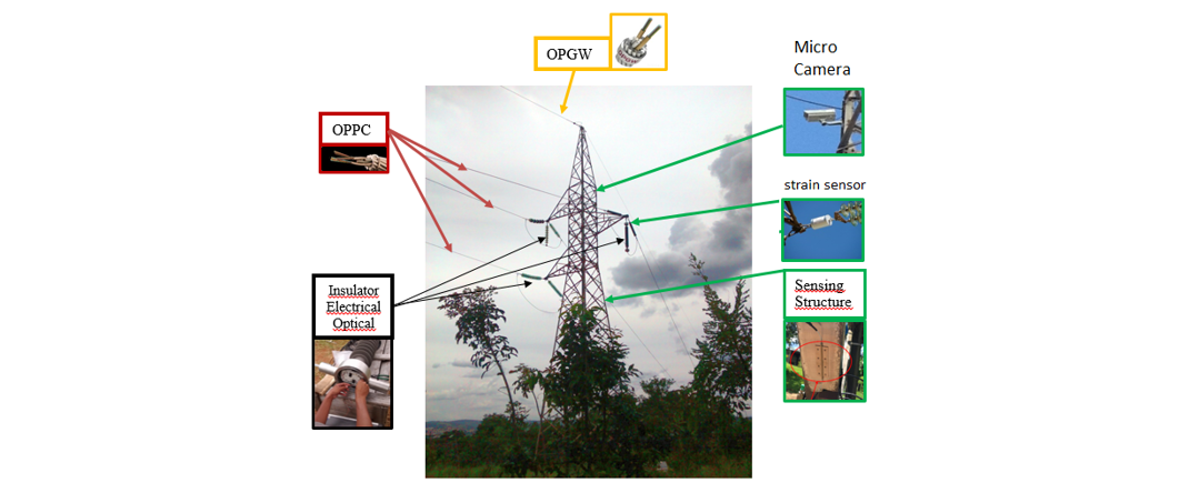
Figure 1 - Synergic overhead transmission line network representation
| Parts | Applications | |
|---|---|---|
| ground wires – OPGW |
|
|
| single or bundle conductor phase – OPPC | ||
| insulator electrical and optical | ||
| tower and foundation | ||
4.2. Electrical & optical conductor and insulator
Furukawa Electric in Brazil developed the OPPC conductor. They have modified a traditional ACSR (Aluminum Conductor Steel Reinforced) Linnet 336 mcm conductor to one similar ACSR-OPPC galvanized steel wires and one stainless-steel tube with 6 single mode fibers optics, according to Figure 2.
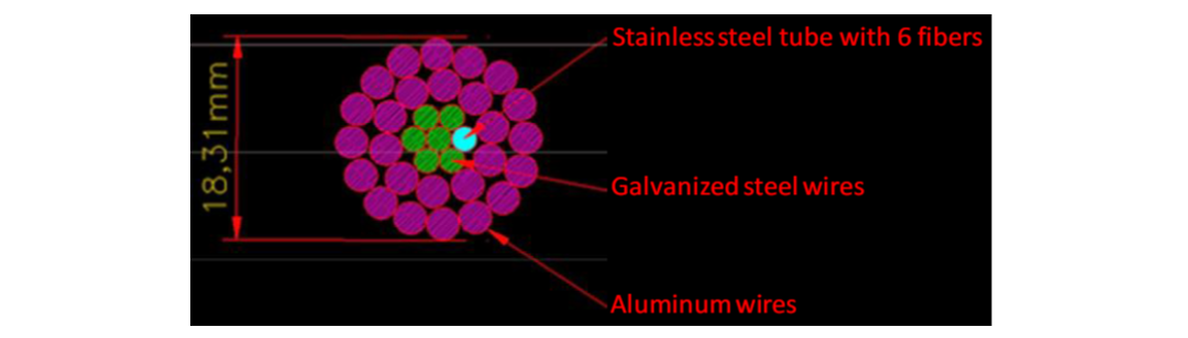
Figure 2 - The cross section of the Optical Phase Conductor – Linnet 336 - OPPC
CPqD and Balestro in Brazil developed the fiber optic embedded insulator as showed in Figure 3. They modified a 138 kV rigid fiber glass/silicone structure (line post) . Six optical fibers pass through a hole constructed inside the fiberglass insulator. The hole is filled with a special material to prevent partial discharges. Figure 3(a) shows the insulator supporting the sensor cables. In Figure 3(a), (1) is the sensor cable, (2) is the insulator, (3) is one optical fiber splice box constructed in the same insulator body, (4) is optical cable that connect the fibers in the ground end of insulator with the optical fiber transmission cable and (5) is the part of a tower of the SOHT Network. Figure 3(b) shows the internal view of the splice box of the insulator.
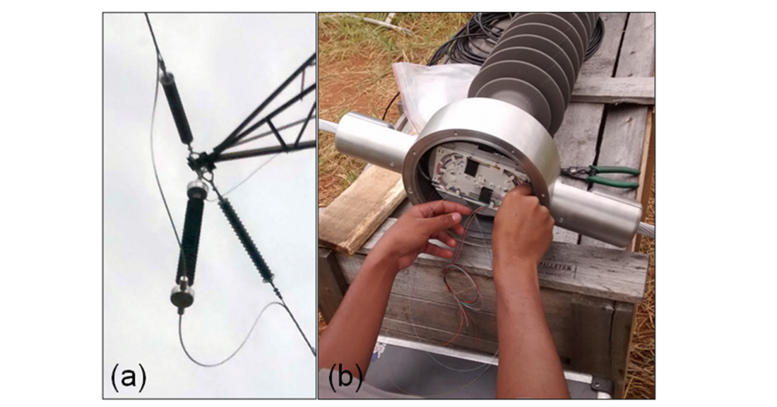
Figure 3 - (a) The fiber embedded optic insulator supporting the sensor conductor and (b) optical fiber splice box that is part of the new insulator
4.3. The monitoring and data communication system
The broadband data transmission system uses Coarse Wavelength Division Multiplexing - CWDM technology [18]. In this technique, several optical signals at different wavelengths are connected in a single optical fiber using devices known multiplexers (mux). Some of these signals can be removed or re-inserted into the fiber link using devices known optical add-drops. To monitor the synergic OHT and simultaneously allow the transmission of data between substations in the same fiber, it has used the network architecture shown Figure 4, which it is a CWDM bus topology. In this case, two transmission/reception elements (CWDM terminals) are used in each substation to multiplexing the monitoring and the communication signal. The signals coming from any external transmission equipment with generic optical output are connected to the optical input of a given SFP (Small Form-factor Pluggable). These SFP are used for both, telecommunication and data communications applications [19]. The transceiver provides the adaptation of this signal at the correct wavelength for transmission on the CWDM terminal. Another CWDM terminal, placed at the opposite substation, deliver these signals to the associated transmission equipment. In the CWDM terminal, the transmitter unit has the function to convert the optical signals of up to 8 clients received in their inputs into up to 8 standardized CWDM signals on their output. The conversion is /performed by SFP transceivers. The transmitter unit is composed of a main board (motherboard) in which two-power supply boards are coupled to a supervision board and eight SFP CWDM transceivers. One of the great advantages of CWDM is that it is cost-effective compared to other WDM systems, such as, dense wavelength division multiplexing (DWDM) [20]. DWDM can also be used providing denser channels allocation.

Figure 4 - CWDM in SOHT Network architecture for monitoring and data transmission
5. The medium, low and neutral voltage
The difficulty in choosing wireless or cable data communication technologies to use in the electric power sector can greatly influence the prospects for its expansion on a large scale. A decision-making model for which technology to be used becomes fundamental for development plans in updating of the assets of utilities in the electricity distribution sector. The concept and platform of Synergic Networks are based on a model to define which type of data communication technology for networks must be used. The model is intuitive and easy to apply. Assets with no mobility use a wired cable commutation network while assets with mobility must be a wireless network. Table 3 presents the main possibilities of the model.
| Asset | Mobility | Type of Data Communication Network to be installed |
|---|---|---|
Power Plant | No | Wired cable |
Overhead Transmission Lines | No | Wired cable |
Distribution Lines | No | Wired cable |
Cable and conductor | No | Wired cable |
Tower and Pole | No | Wired cable |
Transformer | No | Wired cable |
Switching | No | Wired cable |
Metering | No | Wired cable |
Vehicles of Workers | Yes or No | Wireless or Wired cable |
Workers | Yes or No | Wireless or Wired cable |
5.1. The representation of the Synergic Network
Two pilot projects of experimental SN were initiated at UniverCemig Site in Brazil. The first trial was the distribution network in four sections of medium voltage on 13.8 kV and neutral cable that was adapted using OPPC (1/0; 4/0; covered 50 mm2 e 3/8 steel bare) cables with twenty-four optical fibers with associated hardware. The second pilot was the distribution network in four sections low voltage on 220 V that was adapted using a new low voltage Aerial Bunched Cable (ABC) synergic cable (three insulated phases of covered cable 70 mm2; bare cable neutral of 70 mm2 and two microtubes for fibers optics with 14 and 18 mm of its diameters).
5.2. Elements of the medium voltage
The first implementation involved the replacement of cables in the 13.8kV distribution network. The replacement OPPC cables have similar electrical and mechanical characteristics as the existing distribution cable network infrastructure in Cemig. The central phase was replaced by an OPPC 4/0 bare cable and with termination isolator for optical continuity at the ends strain section. For the overhead distribution network on 13.8 kV, it was replaced the phases to OPPC with the installation of termination insulator and optical tool as showed in Figure 5.
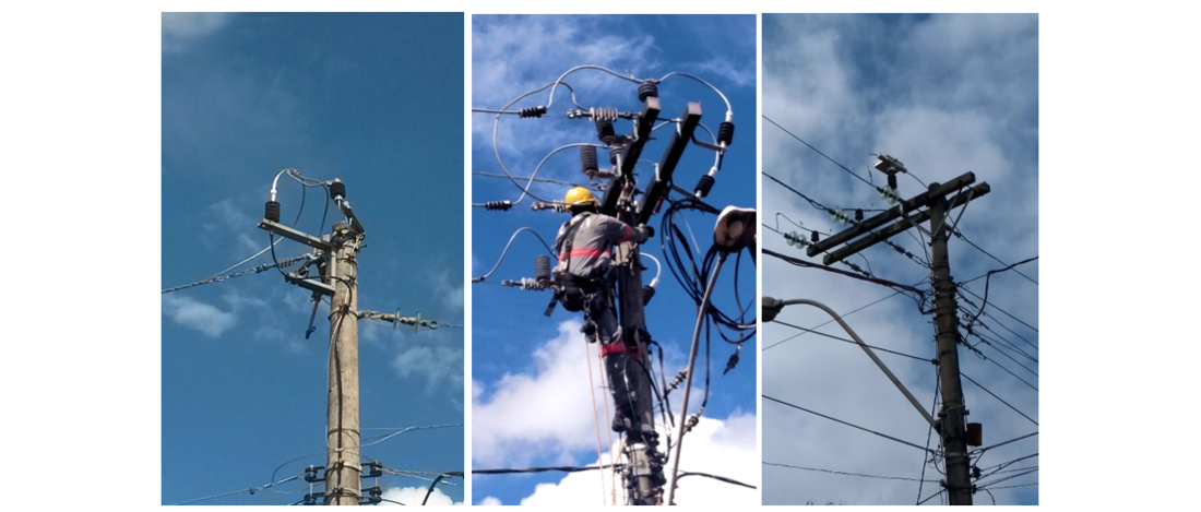
Figure 5 - The termination of optical fibers embedded optical insulator of 13.8 kV (left and center) and setup of fixed on the pole (right)
5.3. Elements of the low voltage
The second pilot implementation consisted of the replace of the low voltage Aerial Bunched Cable (ABC) system in the same section of the first pilot. It was defined the installation of new ABC synergic cables to complete the last mile and it is very similar to the OPLC (Optical fiber composite Low-voltage Cable) [3], but the novelty here was to use the synergic ABC cable added with micro tubes of optical fibers as showed its representation in Figure 6. The advantage of the synergic ABC cable is the easy access to the optical fibers in the pole.

Figure 6 - The representation of ABC synergic cable for low voltage
5.4. Elements of data communications in optical fiber
The optical fiber splice was planned for installation on the poles at a height above the low voltage cables. The microtube structure in the test pole is shown in Figure 7. The Figure 8 (a) shows optical splice boxes and optical termination boxes installed on pole and Figure 8 (b) shows view of depollution urban centers pole in the synergic medium and low voltages distribution and fiber optical data communications networks at Cemig.
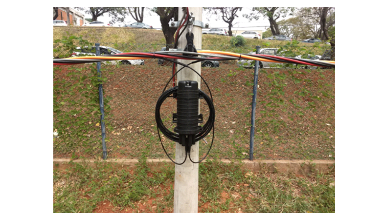
Figure 7 - The optical fiber access of ABC synergic cable in array of low voltage installed on test field of poles
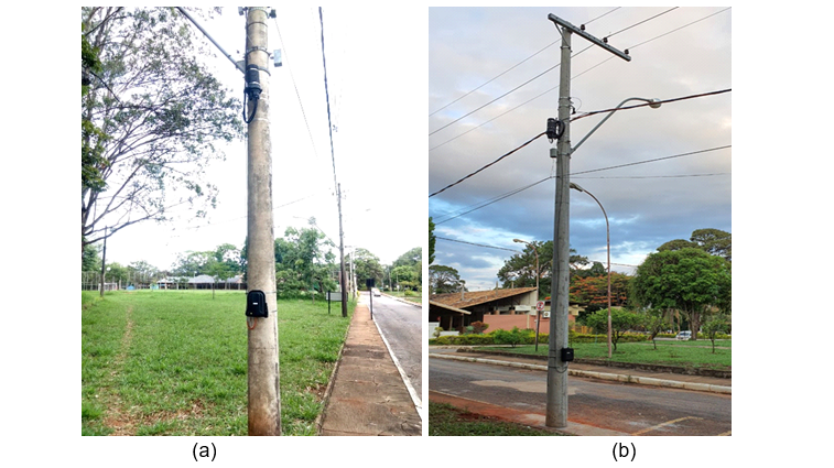
Figure 8 - (a) The optical splice boxes and optical termination boxes installed on pole and (b) View of depollution urban centers pole in the synergic medium and low voltage distribution and fiber optic data communications networks at UniverCemig site in Brazil
5.5. The Inference of market
The medium and low voltage pilots projects result in energy power distribution and data communication networks that are both part of Smart Grid solution using optical fibers in the core of the cables in MV cables and in the LV ABC. The expansion of optical fibers broadband networks along with the energy distribution networks is a very promising market for the diffusion of SN platform, as it will influence the same customer of utilities of electric energy and communication companies by:
- Brings electric energy's customers closer to broadband networks in last mile;
- Digitalization Utility;
- Increased operational safety of power transmission and distribution networks;
- Drastic reduction of visual pollution of networks on city streets;
- Drastic reduction of environmental pollution (optical fiber does not generate radio frequency).
5.6. Advanced Sensing
The trial installation of SN in Brazil site was used also to test some advanced optical sensing system described below:
- Broadband data transmission concomitant to monitoring the physical integrity of conductors: this system [17] used 8 channels of Coarse Wavelength Division Multiplexing (CWDM) technology adopted as a platform for monitoring the physical integrity of OPPC and communication of broadband data (through the same optical fiber) with video at 1.25 GbE simultaneously to the monitoring process for the OHT smart grid networks. The system was characterized in terms of maximum distance from the substation to the critical area (which we designated by critical span) and the time of actuation using 50 km of single-mode optical fiber.
- Optical low power instrument transformers: LPIT using power-over-fiber (PoF) for voltage and current measurements [13] were tested with powering, metering, and data transmission performed simultaneously in the MV OPPC cable.
- Substation perimeter intrusion detection. The interferometry technique applied in fiber optic cables for the immediate detection of attempts at physical intrusions in critical installations. The technology uses a laser, which transforms the fiber optic cable into a distributed microphone of the highest sensitivity. The optical fiber, such as a microphone, captures the vibration signatures differentiate intrusion threats from other irrelevant events, such as wind and rain and vehicle noise, etc.
- Video surveillance. The environmental monitoring by WEB digital camera on poles of SN can still prevent failures in the electrical system (e.g., identifying and preventing fires to reach transmission and distribution networks) and help protect conservation areas environmental [14].
- Other experiments are described in [15].

Major changes are expected in the electrical network sector with implementation of SN such as:
- Reduction of cables on electricity distribution poles shown in Figure 8.
- Physical interconnection of assets and all supervisory and control systems in a single database and controlled autonomously
- Increased safety of transmission and distribution lines against cyber-attack as shown in Table 3.
In the data communications sector, beyond competitiveness, the SN can reach:
- New possibility to install optical fibers in sharing assets of the electric energy sector.
- Rural or remote locations to provide differentiated services according to the user profile.
- Replace or integrate several large-area wireless networks, where synergistic networks are being deployed.
- Reduce the OPEX in O&M of its optical fibers network in the high robustness platform of SN.
These major changes will promote the new platform of use for the electric energy sector and data communications networks. The pole infrastructure of distribution networks is increasing the overloaded by the coexistence of several cable data communications networks, mainly in locations where the demand for data telecommunications services from ISP (Internet Service Providers) is high. In addition to these, the needed broadband by public agencies for monitoring security, operation, and traffic control, among others in the “smart” cities.
It was important to develop the first-generation SN on commercial applications to provide guidance and background research for the standards and procedures to be developed.
It was essential to perform functional validation of the first-generation SN system which was based on commercially available applications. The validation will form input into the creation of standards and procedures.
Standards and methods for planning, design, construction, and O&M of SN must be developed. Figure 9 (b) shows the common practice of building electric energy and optical fibers broadband networks in a completely traditional and independent way each other.
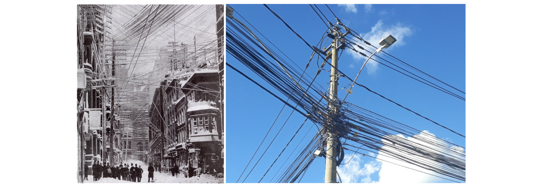
Figure 9 – (a) The trouble of pole wiring in 1888, (b) visual pollution in urban centers in the electricity distribution and data communications networks in 2022 in Brazil
6. Optical Sensing
6.1. Strain and Vibration Sensing by FBG
Figure 10 shows the optical strain and vibration sensing system fiber Bragg grating - FBG placed at body tower. At this point the sensing hardware does not need to be energized and insulated. This is the first big advantage of fiber optic sensor technology. Normally the unit to be monitored is located with 100km of the optic interrogator system with line of site telecommunications.
The FBG optic sensing permits measuring:
- vibration and strain of tower,
- footing and conductor movement,
- ampacity can be monitored directly or indirectly in real time.

Figure 10 - FBG Interrogator and optics strain and vibration applied at 138 kV tower
6.2. Optic Sensing Integrity of Conductor
The assumptions defined for the monitoring and data communication system are the following:
- the system must be fast enough to prevent automatic reclosing with broken conductor;
- the same optical fiber used in the monitoring system should be shared with the telecommunications services.
Considering these premises, it was proposed to the monitor system using CWDM technology [11] that is widely used in telecommunications. The principle of operation of the system is based on the measurement of reflected power from the fiber mirrors devices installed into optic boxes. The interruption of the reflected light power caused by any damage in the optical fibers embedded in the sensor cables will be detected by the CWDM terminal. The receivers of the transceivers detect these signals and internal electronic circuits of the transceivers generate a counter in a network packet that sets a limit to its validity TTL (Time To Live) level "1" output when these signals are not present due to cable failure. The Figure 11 illustrates this situation in a simplified way. Each TTL alarm output from each transceiver is read by the supervision board where an appropriate logic true table programmed in a microprocessor check if the alarms correspond to the conductor broken condition or not. In case of confirmation of dropping of the conductor cable, this board will activate another signal using an appropriate electrical interface and it will send it to an appropriate input of the protective relay of the OHT, to avoid automatic restart.

Figure 11 - The receivers of the transceivers detect the reflected signals and the electronic circuits of the transceivers generate a TTL level "1" output when these signals are not present due to cable failure [11]
6.3. Fiber Bragg grating and free-space-optics
One of the variable desired in the existing OHT is the heating of the conductor caused by the electric current and weather parameters. The temperature sets the limit for safe design operation of the conductors. Thus, it is important to monitor the temperature of conductor. Fiber Bragg grating (FBG) sensor is one of the best technologies to monitor temperature or strain in high voltage systems. The main problem is to connect the fiber and the sensors in the high voltage lines. The traditional solution adopted is using one composite insulator with integrated fiber optic cable. This solution demands to change the ordinary insulator. For this reason, a new approach to connect the sensor light from the high voltage to the ground potential was proposed mainly for existing OHT. This approach uses a pair of optical collimators in free-space-optics (FSO) to transmit and receive the optical signals from optical fiber placed in ground potential to the FBG fiber optics at high voltage potential. The use of kits to fix and adjust the collimators avoids the change of an ordinary isolator. In [11] the Figure 12 shows the two types of FSO/FBG setup systems aimed for temperature sensing. Figure 12 (a) shows the system diagram to monitors the temperature of bus bars in substations and Figure 12 (b) shows the system diagram to monitors the temperature in existing OHT. Collimator’s pairs must be protected against natural effects such as mechanical deformation caused by the temperature or optical attenuation caused by rains.
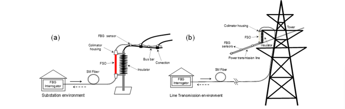
Figure 12 - FSO/FBG systems diagram aimed for temperature sensing: (a) bus bars temperature monitoring system in substations and (b) OHT lines temperature monitoring system
The Figure 13 shows a simulated representation of optical temperature system working in bus bar at part of a high voltage substation. Basically, the monitoring system connects the signals of the FGB fixed in bus bar at high voltage part. This air transmission can be made in the air outside or inside the isolator. For outside a pair of fiber collimators placed in the fiber ends enlarges the light spot size to reduce the alignment problems. The communication data system can be done at high voltage part to interrogator with the same fiber optic of sensing. This is another advantage of the fiber optic sensing technology, and it is an example of application the synergic bus bar concept at substation.
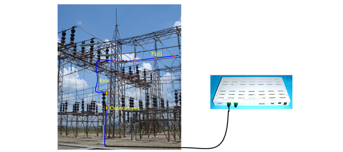
Figure 13 - Simulated representation of optical point temperature system working in bus bar at high voltage part of substation
The Figure 14 shows a trial FSO system installed in the UniverCemig site. The influence of environmental parameters in FSO performance was investigated and the main influence in the coupling loss is related to water in rain. Some improvements in the collimators packaging can mitigate this influence, such as the use of properly designed vents. The oscillation in the power due to the thermal variation is not too critical if the optical sensing technique does not use amplitude variation measurement, instead of frequency or polarization.

Figure 14 - The field test of FSO system conducted in the experimental high voltage synergic transmission line placed in UniverCemig site, Sete Lagoas, Brazil
6.4. Distributed temperature and strain and vibration sensing
The OPPC conductor offers extra monitoring possibilities. Thanks to the linear and nonlinear effects that can be presented in optical fibers, such as Raman, Brillouin and Rayleigh [21] it is possible to monitor the temperature, strain and vibration effects in OHT. With Raman Effect Distributed Temperature Sensing (DTS) it is possible to measure temperature along the optical fiber embedded inside the OPPC conductor, given information about ampacity or forest and fields fires along the OHT. The temperature measured using Raman effect is not affected by the conductor strain, but the range of measurements is below 50 km. Using the Brillouin effect Distributed Temperature and Strain Sensing (DTSS) is possible to measure both temperature and strain in the OHT. Complex methods must be used to separate these two parameters in the evaluation tests. The range of measurement using Brillouin effect is up to 150 km. The Rayleigh effect Distributed Acoustic System (DAS) gives information about vibration along the optical fiber embedded inside the OPPC conductor. The range of measurement using Brillouin effect is up to 40 km and is therefore most applicable in urban areas. The DAS technology is one of the largest sources of innovations for optical sensing nowadays.
6.5. Optical LPIT
Data networks using OPPC conductors have data completely enclosed in optical fibers which it makes them much more restricted to improper access or attempted cyber-attacks, along with to operational data in the field. The Figure 15 shows an experimental application of optical current and voltage equipment in a physically closed wired network in the UniverCemig site [13].
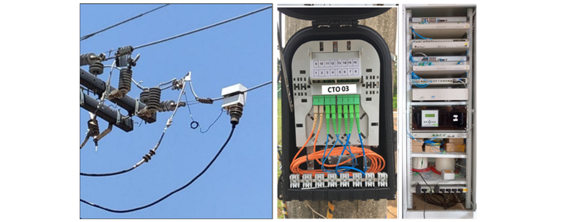
Figure 15 - Didactic representation of access in optical wired data network and electrical current and voltage measurement in closed network
6.6. Micro video camera sensor powered over fiber
Figure 16 shows a non-continuous sensor operating technique to achieve a long reach sensing system, using power over fiber (PoF) in single mode fiber (SMF) [13]. Due to the use of super-capacitors and logical circuits in the sensor unit, the laser energy provided by PoF can be converted and stored for using in an appropriated time. We demonstrated this approach with a micro video camera sensor powered by a 4.4 km SMF link in laboratory and by a 1.6 km link using optical ground wire cable (OPWG), installed between the power substation and a tower on a138 kV OHT.
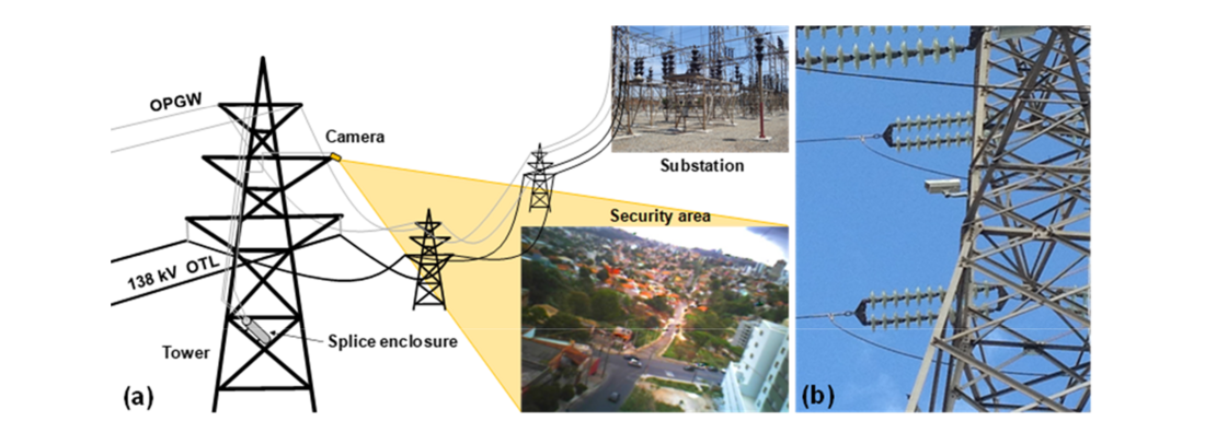
Figure 16 - Micro video camera in power over fiber (PoF) using 1.6 km link optical OPWG
6.7. Other Potential Applications
The presence of optical fiber inside the conductor opens possibilities such as and can create many new functions for utilities. For example, transmission of meteorological data, data transmission of autonomous inspection robot, drones, or serving as a communication way of asset management teams in remote sites. The optical fiber in the last mile can also be a new and easy way to get the optical fiber in the customers houses providing simultaneously services of electricity and telecommunications Giga Passive Optical Network (G-PON).
7. LAB of Development and Field of Trial
Sete Lagoas city in Minas Gerais state of Brazil was the place chosen for installation and testing of the complete system has already detailed. Figure 17 (a) shows a photograph of the sensor cable installed in the test OHT and Figure 17 (b) shows a photo of the CWDM terminal installed in a control broadband data room site. After implementation of the monitoring network, all the optical fibers were characterized with optical time-domain reflectometer (OTDR) to verify the optical attenuation along the link, and it was observed that fiber signal attenuation due to splices along the links agreed with the requirements. The devides used in wavelength-division multiplexing systems for multiplexing and routing different channels of light (add-drops) and device which can reflect light (mirrors) were installed in the control room to enable configuration of various optical network topologies and allowed the simulation of faults (conductor breaks simulation) at different points of the link as well as the combinations of different types of faults. In a real application, the add-drops devides and mirrors will be installed in the splice box used in the fiber-embedded insulators, such as, the box shown in Figure 3 (b).
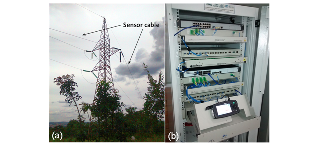
Figure 17 - (a) Sensor cable OPPC installed in two spans in the field trial and (b) CWDM terminal
Two coils of single-mode fiber of 5 km each were added to the fiber distribution rack to extend the total length of the optical fiber link. This way the total link was 17 km long. The functionality tests were performed simulating a broken OPPC conductor simultaneously with the operation of the monitoring system. To perform the validation tests, the network analyzer was used to generate data traffic. Data traffic at 1.25 Gigabit Ethernet - GbE was inserted into one of the data communications channels, and simultaneously high-resolution videos were transmitted in both directions of the optical link. In the performed tests, it was verified that each system (monitoring and the telecommunication system) operated properly and independently. The results obtained demonstrated the feasibility of the simultaneous use of an optical fiber network for the joint operation of monitoring and broadband transmission system.
8. Overview of maintenance procedures in synergic network
8.1. New asset
When the construction of OPPC and Optical and Electrical Isolator and accessories were well handled by the construction team it is expected that the same procedures are used to OPPC like OPGW cable. The OPPC maintenance procedures must be development. The same behavior of good optic connection is expected with low loss of optical signal.
8.2. Existing asset
The SN could be applied in existing asset, but it is more difficult than in new projects. OPGW must be considered as the main optical network but sometimes it is not installed in existing asset. In this case we must try replacing the conductors or to install a new optical cable around the existing conductor, although this is not easy to achieve.
9. The second generation of synergic network
The second generation of synergic network (2G-SN) will be a revolution for asset management in the electricity sector. The 2G-SN is completely defined when all parts of the generation, transmission and distribution equipment will have fiber optics and are connected in a robust network. As detailed in [23] a practical application of a wind turbine with optical sensing network inside it has created.
10. Conclusion
This paper showed an overview of the application where electric energy and data telecommunication companies no longer operate independently but share unique infrastructure and provide higher quality of services, with high operational efficiency and optimize global investment in the expansion of electric energy and optical fibers broadband networks. This new network was called "Synergistic Network - SN". Also, this work presented an overview of the three real-scale pilot installations of a SN platform in Brazil – Cemig Utility. Despite being relatively small, it was fundamental to begin to consolidate the first generation of SN concept and its platform. The three pilot deployments of OPPC conductor on 138 kV and OPPC cables on 13.8 kV and ABC synergic cables on 220V were conducted, as described in this paper was essential to build and prove the viability of SN and their elements
The first generation of SN showed us that, the development of the optical system for monitoring the electrical and mechanical behavior related to broadband data transmission was a breakthrough in electric energy and data sectors. It gave rise to an expanded of Smart Grid capability in electrical sector. In the specific case, it will be the use of the same physical asset device (the OPPC conductor and ABC synergic cable). This concept should be applied from high to low voltage, allowing a lot of new sensing application with electricity and telecommunication data services. The technological challenging milestone has been successfully working in Brazil since 2008. The new step in progress is to encourage the electric industry and broadband data services around the world to build and produce the SN with all hardware and software, like conductor OPPC and ABC synergic cable and embedded electrical & optical insulators parts. New projects, in expansion or refurbishment, is the essence for digital modernization of utilities. The state of the art for smart grid infrastructure by using purely optical technologies to explore, low latency, no RF interferences and intrinsic cyber security on high level provided by fiber optics networks. Not unlike other areas of knowledge, the evolution of energy and telecommunication technologies in synergy way and with innovations are required to accelerate the materialization for the digital Utility to improve acceptance of public in the expansion of electrical and data telecommunication sectors.
In addition, the first generation of SN was fundamental to develop the studies, based on commercial applications, to perform the functional validation of the standards and procedures that should be developed. Standards and methods for planning O&M of SN should be developed. It is important to note that currently the synergy between the electricity sector and data communications network infrastructures exists only about the mutual use of the poles and the coexistence is not harmonious as we showed in Figure 9.
It is essential that new and commercial projects and initiatives for the implementation of real cases be carried out to advance the development of the SN, noting that they are not only network elements, but also aspects and procedures, considering that they bring a new approach on the infrastructure of electricity sector and data telecommunications networks. Cemig and CPQD have tested the technology in the field and now it is presenting the solution for utilities, investors, and society. A strategy such as advancing technology through R&D funding program, but if the market perceives the great economic and social gains the expansion of SN can take on incredible goals in the coming years.
Finally, this paper detailed the benefits and its main elements of first generation of SN. Furthermore, the paper briefly showed the field tests in the pilot projects and some sensing systems applied for optical smart grid were described, such as the future of view the second generation of SN was briefly discussed.
Aknowledgments
This concept and trial projects (Cemig P&D-D520/D566/D613) were funded by ANEEL (Brazilian Electricity Regulatory Agency). Special thanks to Cemig, CPqD, Balestro and UniverCemig for their friendly cooperation and dedication to this joint development project.
References
- M. Kim, J. J. Metzner and K. Y. Lee, "Design and Implementation of a Last-Mile Optical Network for Distribution Automation," in IEEE Transactions on Power Delivery, vol. 24, no. 3, pp. 1198-1205, July 2009. doi: 10.1109/TPWRD.2008.2008487;
- EPRI, "Strategic Fiber in the WAN Exploration of Synergistic Fiber Network Deployment for Utility Smart Grid/DA and 5G Mobile Network Operators", 3002013389, (2018).
- L. Jianming, W. Jiye, F. Pengzhan and Z. Zichao, "Application of PFTTH in smart grid," 13th International Conference on Advanced Communication Technology (ICACT2011), Gangwon, Korea (South), 2011, pp. 389-392.
- L. Jianming, Z. Bingzhen and Z. Zichao, "The smart grid multi-utility services platform based on power fiber to the home," 2011 IEEE International Conference on Cloud Computing and Intelligence Systems, Beijing, China, 2011, pp. 17-22, doi: 10.1109/CCIS.2011.6045024.
- Shan Li, Ningxi Song, Guangju Li, The Feasible Analysis of Business Operation Model for Power Fiber to the Home, Energy Procedia, Volume 12, 2011, Pages 53-59. https://doi.org/10.1016/j.egypro.2011.10.009.
- Xie Shu-Hong, Zhang Jian-Min, Li Xin-Jian and Yang Ri-Sheng, “Study of the Power Fiber to the Home Technologies Based on the OPLC Cable”, 60th IWCS Conference, 2011.
- Liu Jianming; Wang Jiye; Fan Pengzhan; Zhuang Zichao, "Application of PFTTH in Advanced Communication Technology (ICACT), 2011 13th International Conference on, vol., no., pp.389 - 392, 13-16 Feb. 2011.
- Jicong Bao, Xinxia Qiao, Ziming Qian, “The Application of Optical Fiber Composite Low-Voltage Cable (OPLC) in China”, 8th International Conference on Insulated Power Cables, 19 – 23 June 2011, Versailles – France.
- Guoliang Nan, Shaofeng Zhang, Yiwei Lin, Guozhong Zhang, Chengdu, China Power Fiber to the Home Opens Up a New Approach of Integration of Three Networks Power Supply Company, ICSGCE 2011: 27–30 September 2011 - Sanmenxia, China
- A. Ashfaq, Y. Chen, K. Yao, F. Jia, J. Yu and Y. Cheng, "Comprehensive Analysis of Temperature and Stress Distribution in Optical Fiber Composite Low Voltage Cable Using Finite Element Method," in IEEE Access, vol. 8, pp. 217380-217390, 2020, doi: 10.1109/ACCESS.2020.3041784.
- J. B. Rosolem; C. A. M. Do Nascimento; D. C. Dini; A. V. P. Pinto; C. A. Hortencio; W. R. Silva; E. F. Costa; R. S. Penze; J. P. V. Fracarolli and V. F. Coelho, “Optical system for broadband data transmission concomitant to monitoring the physical integrity of conductors in overhead transmission lines”, Paris, France, CIGRE Session, Paper B2-101, Aug 26-31, 2018.
- “The new topology of Synergic Overhead Transmission Line Network” - CIGRE PARIS 2018 – TECHNICAL SESSION – GROUP B2 – PS2.
- F. R. Bassan, J. B. Rosolem, C. Floridia, B. N. Aires, R. Peres, J. F. Aprea, C. A. M. Nascimento, and F. Fruett, “Power-over-Fiber LPIT for Voltage and Current Measurements in the Medium Voltage Distribution Networks,” Sensors, vol. 21, no. 2, p. 547, Jan. 2021. https://doi.org/10.3390/s21020547
- D. A. G. Vieira, A. L. Santos, H. C. Yehia, A. C. Lisboa, C. A. M. Nascimento, 2016, Smoke Detection in Environmental Regions by Means of Computer Vision. In: Hatzilygeroudis I., Palade V., Prentzas J. (eds) Combinations of Intelligent Methods and Applications. Smart Innovation, Systems and Technologies, vol 46. Springer, Cham. https://doi.org/10.1007/978-3-319-26860-6_8
- Nascimento, C.; Rosolem, J.; Hortencio, C.; Dini, D.; Obara, L. The First Generation of Synergic Overhead Transmission Lines Network. In Proceedings of the CIGRE-IEC 2019 Conference on EHV and UHV (AC & DC), Hakodate, Hokkaido, Japan, 23–26 April 2019.
- "Building the invisible city". The New York Historical Society.
- "Optical system for broadband data transmission concomitant to monitoring the physical integrity of conductors in overhead transmission lines”, In: 2018 CIGRE Session, Paper B2-101, Paris, 2018.
- “CWDM Technology, Standards, Economics & Applications”. Available at: http://citeseerx.ist.psu.edu/viewdoc/download?doi=10.1.1.195.9690&rep=rep1&type=pdf “NGCP: Informal settlers hamper transmission line projects”. Available at: https://www.rappler.com/business/industries/173-power-and-energy/101137-ngcp-informal-settlers-transmission-lines
- SFF Committee, “INF-8074i Specification for SFP (Small Form factor Pluggable) Transceiver”, Rev 1.0, May, 2001.
- “Wavelength multiplexing (WMD) for electricity utilities”, CIGRE Publication TB 131, 2011.
- "Distributed Temperature Sensing: Review of Technology and Applications," in IEEE Sensors Journal, vol. 12, no. 5, pp. 885-892, May 2012.
- Rosolem, J. B.; Bassan, F. R.; Pereira, F. R.; Penze, R. S.; Leonardi, A. A.; Nascimento, C. A. M. “Fiber powered sensing system for a long reach single mode fiber link and non-continuous applications”. Proceedings of the SPIE, Volume 9157, id. 9157AE 4 pp. (2014). DOI: 10.1117/12.2058672.
- T. Bosselmann, S. Strack and J. R. Weidner, Advanced condition monitoring of new and upgraded turbine generators for highly flexible grid demands using special fibre optic sensors - CSE N°24 FEBRUARY 2022.
Biographies
B. N. AIRES was born in São Gonçalo do Sapucaí, MG, Brazil, in 1988. He received the B.S in Electrical Engineering from the National Institute of Telecommunications in 2012. Since 2012, he is a researcher of CPqD Telecommunication Research and Development Center, Campinas, Brazil.
E. F. da COSTA holds a PhD in Electrical Engineering from the State University of Campinas. He is currently an engineer at the Telecommunications Research and Development Center Foundation. He has experience in Electrical Engineering, with emphasis on electronic and optoelectronic circuits, working mainly on the following topics: optics, fiber optics, fiber optic sensors, Smart Grid, Power Line Communications (PLC) and telecommunications in general. He has been acting as a researcher and coordinator of R&D projects for the Electric Sector.
J. B. ROSOLEM was born in Fartura, SP, Brazil, in 1963. He received the Ph.D. degree in electrical engineering from the University of Sao Paulo, São Carlos, Brazil, in 2005.Since 1990, he has been a Researcher with the CPqD Telecommunication Research and Development Center, Campinas, Brazil. He has been involved in the design of optical sensing systems and research in optical sensors for utility applications, such as FBG, DTS, and PoF. He is the author of more than 180 papers.
A. A. DELLALLIBERA was born in 1963 in São Paulo, SP. Graduated in Electrotechnics, he has worked since 1985 in the Balestro Electromechanical Industry, in the engineering departments and in the high voltage laboratory. Throughout his career he has been involved with equipment design, high voltage testing and application cases for surge arresters and insulators. He currently works focused on new technologies and application engineering. He is currently coordinator of ABNT's Lightning Rod Studies Commission, member of Cigré since 2001 and Brazilian member of TC 37 (Surge Arresters) of the IEC.
C. A. M. NASCIMENTO was born Brazil in 1968. He received the Ph.D. degree in electrical engineering from Federal University of Minas Gerais, Belo Horizonte, Brazil. He has been working in Cemig since 1989, Belo Horizonte, Brazil. He develops and applies real-time monitoring technology coupled with intense use of mathematical, statistical computation tools, and optimization algorithms to optimize investments on electrical power transmission and delivery engineering.
Vivendhra NAIDOO Electrical engineer/MBA with more than 24 years experience in engineering work and management. Broad international expertise and experience, with the last 20 years specializing in overhead line design up to 765kV. Mr. Naidoo has worked on powerline projects in more than 10 countries in different capacities. Currently working as Manager of the Energy Department in EFLA AS, Norway. Responsible for strategic tasks and utility projects worldwide.